BAG TECHNIQUE Bag technique-a tool making use of public health bag through wh...
PPT.pptx
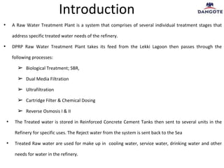
1. Introduction
• A Raw Water Treatment Plant is a system that comprises of several individual treatment stages that
address specific treated water needs of the refinery.
• DPRP Raw Water Treatment Plant takes its feed from the Lekki Lagoon then passes through the
following processes:
➢ Biological Treatment; SBR,
➢ Dual Media Filtration
➢ Ultrafiltration
➢ Cartridge Filter & Chemical Dosing
➢ Reverse Osmosis I & II
• The Treated water is stored in Reinforced Concrete Cement Tanks then sent to several units in the
Refinery for specific uses. The Reject water from the system is sent back to the Sea
• Treated Raw water are used for make up in cooling water, service water, drinking water and other
needs for water in the refinery.
3. Feed Water Specification
PARAMETERS UNIT WATER CHARACTERISTICS
pH - 7.0 – 8.0
Temperature Deg C 22.4- 33.7
Turbidity NTU 3.47 to 50.40
Total Suspended Solids mg/l 2.67 to 24.8
Total Dissolved Solids (TDS) mg/l 29.05 to 1200
MO Alkalinity as CaCO3 mg/l 8.69 to 120.5
Calcium Hardness as CaCO3 mg/l 2.0 to 27.6
Magnesium Hardness as Mg mg/l 1.42 to 36.75
Sodium as Na mg/l 5.69 to 358.12
Potassium as K mg/l 1.29 to 11
4. Feed Water Specification
PARAMETERS UNIT RAW WATER CHARACTERISTICS
Boron as B mg/l 0.001 to 0.0041
Chloride as Cl mg/l 8.61 to 546.5
Sulphates as SO4 mg/l 0.75 to 78.35
Reactive Silica as SiO2 mg/l 5-6.5
Total Silica mg/l 8 (Max)
Total Iron as Fe mg/l 1.0
BOD mg/l 16 to 92
COD mg/l 32 to 137.2
TKN mg/l 32.3 to 48.4
Oil & Grease mg/l 10.0
Nitrate as N mg/l 0.53
5. 1. Raw Water Intake Section
• The Intake is taken from Lekki lagoon channeled through a canal into a forebay before it is sent to the
pump house.
Raw Water intake flow rate = 5570m3/h
Maximum design flow of water through the canal = 6330 m3/hr (future inclusive)
Number of Pumps = 4 (3 standby and 1 future)
Pumps capacity = 2785 m3/hr each, future=1050 m3/hr.
3 different sized screen (mesh sizes) = 80mm, 18mm and 5mm
RWTP Process
6. 2. Biological treatment Section
• The Biological treatment section comprises of the Sequential Batch Reactor (SBR) to reduce the
Total Suspended Solids (TDS), Biological Oxygen Demand(BOD), Chemical Oxygen Demand(COD),
Total Kjeldahl Nitrogen(TKN) and other contaminants from raw water.
• The raw water is channeled through Distribution box to eight SBR Basins from the pumping station
• Surplus Activated sludge from SBR is sent to a thickener, then dewatered in a Bio-sludge Centrifuge.
The supernatant from the thickener and centrate from the centrifuge are routed back to the
biological treatment section.
RWTP Process cont’d
Centrifuge
for Bio-
sludge
UF SKID RECYCLE PROVISION
SBR
Thickener for
Bio-Sludge
Centrate
Tank
From Raw
water
Intake
Sludge Line
From Lamella
Clarifier (DMF
Section)
7. RWTP Process cont’d
3. Dual Media Filter (DMF) Section
• The treated water from biological treatment section is collected in a filter feed tank, where ClO2 is
dosed to arrest microbial growth.
• The suspended particles contained in the treated water are removed by passing it through Dual Media
Filters(DMF).
• Coagulant (Ferric chloride) is dosed to aid coagulation and facilitate removal of suspended solids.
• Part of the filtered water is used for backwashing of filters and thereafter the waste backwash is sent
to internal backwash treatment section
8. RWTP Process cont’d
4. Ultrafiltration (UF) Section
• The outflow from Dual Media Filter is fed to Ultrafiltration (UF) unit via basket strainers.
• Ultra filtration is a membrane process in which a porous membrane is used to separate or reject
colloidal and particulate matter.
• Filtrate from UF is sent to RO Feed tank while the chemical waste from UF CEB/CIP is sent to
Neutralization Pit.
• The UF backwash is routed to the Reject holding tank from where it will be disposed off to RWTP
battery limit i.e. to the sea.
9. RWTP Process cont’d
5 Cartridge Filter & Chemical Dosing
• The filtered water sent to the RO-I feed tank is pumped through to the cartridge filters. This is to
ensure that no particle of size greater than 5 micron enters the Reverse Osmosis System.
• There is a chemical dosing system which caters for the need of the RO-I system, these chemicals and
their functions are:
1. Acid dosing to adjust the pH.
2. SMBS to remove any residual chlorine in feed water.
3. Antiscalant to inhibit the precipitation of sparingly soluble carbonate salts.
10. RWTP Process cont’d
6. Reverse Osmosis Section – I & II
• Reverse Osmosis is a water purification process used to remove ions and unwanted particles from
water under applied pressure through a semi-permeable membrane.
• The Reverse Osmosis system is configured in a 2-Stage arrangement to allow for high rejection of
dissolved solid concentrations so that the permeate water complies with the desired quality for its use
in the refinery.
• RO-I system is designed for a recovery of 85%. Permeate from the RO-I System is sent to RO product
storage tank, while the RO-I reject is stored in RO–II feed tank, further it goes through same process as
RO-I.
11. RWTP Process cont’d
• RO-II system is designed for a recovery of 70%. RO-II permeate stream is routed to RO Product water
storage tank where it is blended with RO-I permeate. A tapping from RO-I & RO-II permeate line is
routed to the Drinking water intermittent tank.
• The blended permeate stream meeting the treated water characteristics is pumped to RWTP battery
limit i.e., RCC Tank.
• The RO-II reject stream is routed to ClO2 Contact tank for partial reduction of COD with ClO2 dosing
whereas the chemical cleaning waste is sent to the Neutralization pit.
12. Treated Raw Water Specification
PARAMETERS UNIT TREATED RAW WATER CHARACTERISTICS
pH - 7.0 – 8.0
Turbidity NTU < 1
Total Suspended Solids mg/l < 1
Total Dissolved Solids (TDS) mg/l < 137
MO Alkalinity as CaCO3 mg/l < 57
Calcium Hardness as CaCO3 mg/l < 30
Magnesium Hardness as Mg mg/l < 1.6
Sodium as Na mg/l < 28
Potassium as K mg/l < 1.2
Boron as B mg/l < 0.0041
Chloride as Cl mg/l < 37.7
13. Treated Raw Water Specification
PARAMETERS UNIT TREATED RAW WATER CHARACTERISTICS
Sulphates as SO4 mg/l < 14.0
Nitrates as NO3 mg/l < 0.3
Reactive Silica as SiO2 mg/l < 2.0
Total Silica mg/l < 2.0
Total Iron as Fe mg/l < 0.1
BOD mg/l < 5
COD as KMnO4 @ 100 Deg C mg/l < 5
TKN mg/l < 5
Oil & Grease mg/l BDL
Nitrate as N mg/l < 1
Residual Chlorine Dioxide mg/l 2
14. RWTP Process cont’d
7 Drinking Water Treatment Section
• A part of the permeate streams from RO-I and RO-II are collected in a separate intermittent tank
sourced as drinking water..
The flow rate of Drinking water section = 20m3/h
There are several chemicals dosed into this unit:
• Chlorine dioxide to arrest microbiological growth and maintain ClO2 value of 0.2mg/l
• Calcium chloride & Sodium bicarbonate are dosed for re-mineralization purposes.
15. Drinking Water Specification
PARAMETERS UNIT DRINKING WATER CHARACTERISTICS
pH - 8.2 - 8.8
TDS NTU ~600
Turbidity mg/l < 1.5
Calcium Hardness CaCO3 mg/l 100-300
Free residual chlorine dioxide mg/l 0.2
Iron as Fe mg/l < 0.1
Manganese mg/l < 0.05
Color Hazen Units < 5
Taste & Odor Unobjectionable
Coliform Absent (immediately after disinfection)
E. Coli Absent (immediately after disinfection)
Heavy Metals As per WHO standard
Chloride mg/l < 250
16. RWTP Process cont’d
8 Internal backwash section
• Waste from UF CEB/CIP and RO CIP is collected in Neutralization pit.
• The waste from all treatment units will be sent to Carbon contact tank to be treated with Powdered
Activated Carbon (PAC) to further reduce ClO2.
• Subsequently, a lamella clarifier is used to recover the PAC then breakpoint.
• This effluent is dechlorinated using SMBS then passed through final guard to trap residual particles
before it is sent to Reject holding tanks then through effluent transfer pumps to the sea.
• Sludge from the Lamella clarifier in DMF section is routed to PAC sludge sump for further thickening
and dewatering.
• The UF backwash is directly routed to the Reject holding tank from where it is disposed off to RWTP
battery limit i.e., to the sea.