Chapter 2 internal combustion engine
•
1 like•862 views

first law of thermodynamics

Recommended
More Related Content
What's hot
What's hot (20)
Viewers also liked
Viewers also liked (10)
Similar to Chapter 2 internal combustion engine
Similar to Chapter 2 internal combustion engine (20)
Recently uploaded
Recently uploaded (20)
Chapter 2 internal combustion engine
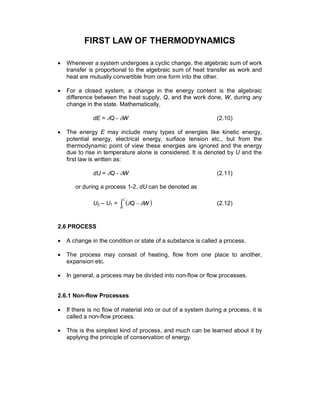
- 1. FIRST LAW OF THERMODYNAMICS · Whenever a system undergoes a cyclic change, the algebraic sum of work transfer is proportional to the algebraic sum of heat transfer as work and heat are mutually convertible from one form into the other. · For a closed system, a change in the energy content is the algebraic difference between the heat supply, Q, and the work done, W, during any change in the state. Mathematically, dE = dQ - dW (2.10) · The energy E may include many types of energies like kinetic energy, potential energy, electrical energy, surface tension etc., but from the thermodynamic point of view these energies are ignored and the energy due to rise in temperature alone is considered. It is denoted by U and the first law is written as: dU = dQ - dW (2.11) or during a process 1-2, dU can be denoted as U2 – U1 = ( )ò - 2 1 WQ dd (2.12) 2.6 PROCESS · A change in the condition or state of a substance is called a process. · The process may consist of heating, flow from one place to another, expansion etc. · In general, a process may be divided into non-flow or flow processes. 2.6.1 Non-flow Processes · If there is no flow of material into or out of a system during a process, it is called a non-flow process. · This is the simplest kind of process, and much can be learned about it by applying the principle of conservation of energy.
- 2. 2.7 ANALYSIS OF NON-FLOW PROCESSES · The purpose of the analysis is to apply the First Law of Thermodynamics to process in which a non-flow system changes from one state to the other and also to develop some useful relations. 2.7.1 Constant Volume or, Isochoric Process · This process is usually encountered in the analysis of air-standard Otto, Diesel and Dual cycles. · Figure 2.1 shows the constant volume process on a p-V diagram. Fig. 2.1 Constant Volume Process · As there is no change in volume, the work ( )ò pdV is zero. · Hence, according to the first law for the constant volume process the change in internal energy is equal to the heat transfer, i.e., dU = dQ = mCvdT = mCv(T2 – T1) (2.13) · For unit mass, du = dq = CvdT V v dT du C ÷ ø ö ç è æ = (2.14) i.e., specific heat at constant volume is the rate of change of internal energy with respect to absolute temperature. 2.7.2 Constant Pressure or Isobaric Process · Figure 2.2 shows a system that changes from state 1 to state 2 at constant pressure.
- 3. Fig. 2.2 Constant Pressure Process · Application of first law yields, dQ = dU + pdV = d(U + pV) = dH (2.15) where H is known as the enthalpy. · Thus, during constant pressure process, heat transfer is equal to change in enthalpy or dH = dQ = mCpdT (2.16) For unit mass, dq = dh = CpdT (2.17) p p dT dh C ÷ ø ö ç è æ = (2.18) i.e., specific heat at constant pressure is the rate of change of specific enthalpy with respect to absolute temperature. 2.7.3 Constant Temperature or Isothermal Process · The isothermal process on a p-V diagram is illustrated in Fig.2.3. · As there is no temperature change during this process, there will not be any change in internal energy i.e., dU = 0, then according to the first law dQ = dW (2.19) or Q1-2 = ÷÷ ø ö çç è æ =ò 1 2 11 2 1 V V VppdV elog (2.20)
- 4. Fig. 2.3 Constant Temperature Process 2.7.4 Reversible Adiabatic or Isentropic Process · If a process occurs in such a way that there is no heat transfer between the surroundings and the system, but the boundary of the system moves giving displacement work, the process is said to be adiabatic. · Such a process is possible if the system is thermally insulated from the surroundings. · Hence, dQ = 0, therefore, dW = - du = -mCvdT (2.21) · Reversible adiabatic process is also known as isentropic process. · Let pVg = C be the law of the isentropic process. For unit mass flow, q1-2 = 0 = w1-2 + u2 – u1 (2.22) or w1-2 = -(u2 – u1) · In other words, work is done at the expense of internal energy W1-2 = òò = 2 1 2 1 dV V C pdV g (2.23) [ ] g g - = - 1 2 1 1 V VCV
- 5. g gg - - = -- 1 1 1 1 2 CVCV when gg 2211 VpVpC == , g gglg - - = -- - 1 1 221 1 222 21 VVpVVp W 1 2211 - - = g VpVp · Using pV = RT for unit mass flow, so w1-2 = ( ) 1 21 - - g TTR ( ) ( )1221 uuTTCv --=-= 2 22 1 11 T Vp T Vp = therefore, ÷÷ ø ö çç è æ ÷÷ ø ö çç è æ == 1 2 2 1 11 22 1 2 V V V V Vp Vp T T g ( )1 2 1 - ÷÷ ø ö çç è æ = g V V (2.24) ÷÷ ø ö çç è æ ÷÷ ø ö çç è æ == 1 2 1 2 1 11 22 1 2 p p p p Vp Vp T T g ÷÷ ø ö çç è æ - ÷÷ ø ö çç è æ - ÷÷ ø ö çç è æ =÷÷ ø ö çç è æ = g g g 11 1 1 2 1 2 p p p p (2.25) ( ) ÷÷ ø ö çç è æ - - ÷÷ ø ö çç è æ =÷÷ ø ö çç è æ = g g g 1 1 2 1 2 1 1 2 p p V V T T (2.26) 2.7.5 Reversible Polytropic Process · In polytropic process, both heat and work transfers take place.
- 6. · It is denoted by the general equation pVn = C, where n is the polytropic index. · The following equations can be written by analogy to the equations for the reversible adiabatic process which is only a special case of polytropic process with n = g. · Hence, for a polytropic process nn VpVp 2211 = (2.27) 1 1 2 2 1 - ÷÷ ø ö çç è æ = n V V T T ÷ ø ö ç è æ - ÷÷ ø ö çç è æ = n n p p T T 1 2 1 2 1 (2.28) and 1 2211 21 - - =- n VpVp w (2.29) 2.7.6 Heat Transfer During Polytropic Process · Heat transfer per unit mass, ( ) ò+-=- 2 1 1221 pdVuuq (2.30) ( ) ( ) n TTR TTCv - - +-= 1 12 12 ( )12 1 TT n R Cv -÷ ø ö ç è æ - += ( )12 1 TT n CC C vp v -÷ ÷ ø ö ç ç è æ - - += ( )12 1 TT n nCC vp -÷ ÷ ø ö ç ç è æ - - =
- 7. ( )12 1 TTn C C n C v pv -÷ ÷ ø ö ç ç è æ -÷ ø ö ç è æ - = ( )( )12 1 TTn n Cv --÷ ø ö ç è æ - = g ( )12 1 TTC n n v -÷ ø ö ç è æ - - = g (2.31) · Hence, ( )1221 TTCq n -=- where, vn C n n C ÷ ø ö ç è æ - - = 1 g (2.32) · Table 2.1 gives the formulae for various process relations for easy reference.
- 9. 2.8 ANALYSIS OF FLOW PROCESS · Consider a device shown in the Fig.2.4 through which a fluid flows at uniform rate and which absorbs heat and does work, also at a uniform rate. In engines, the gas flow, heat flow and work output vary throughout each cycle, but if a sufficiently long time interval (such as a minute) be chosen, then, even an engine can be considered to be operating und-r steady-flow conditions. Fig. 2.4 Illustration of Steady Flow Process · Applying the principle of conservation of energy to such a system during the chosen time interval, the total energy in the mass of fluid which enters the machine across boundary 1-1 plus the heat added to the fluid through the walls of the machine, minus the work done by the machine, must equal the total energy left in the equal mass of fluid crossing boundary 2-2 and leaving the machine. · Expressed in the mathematical form, ú ú û ù ê ê ë é ÷ ÷ ø ö ç ç è æ ++-÷ ÷ ø ö ç ç è æ ++=- 1 2 1 12 2 2 2 22 gz C hgz C hmWQ x or ÷÷ ø ö çç è æ ++D= - gz C h m WQ x 2 2 (2.33) · In the above equation, m donates mass. It is known a, the general energy equation and is the one which illustrates the first law of thermodynamics. · Here, W, is the external work and given by W = Wx - mp1V1 + mp2V2 (2.34) where W is the net work and V stands for volume.
- 10. 2.8.1 Flow Work · The term pV in the above equation is called flow work and must be considered whenever flow takes place. · It is the, work necessary either to push certain quantity of mass into or out of the system. 2.9 WORK, POWER AND EFFICIENCY 2.9.1 Work · Work might be defined as the energy expended when motion takes place in opposition to a force. · Work thus represents energy being transferred from one place to another. 2.9.2 Power · Power is the rate of doing work. · It is generally useless to do a certain piece of work unless it can be done within a reasonable length of time. · When work is done at the rate of 736 Nm/s or 75 kgf m/s, the quantity of power being developed is known as one horse power. · In SI units power is expressed in kW = 1 kN m/s. 2.9.3 Efficiency · It is common practice in engineering to establish a figure of merit for a device by comparing the actual performance of the device with the performance it would have had under some arbitrary set of ideal conditions. · The ratio of actual performance to the ideal performance is called the efficiency of the device. · Since the ideal performance is usually unattainable, the efficiency is usually less than 1. · In internal combustion engines, one of the most important efficiencies is the thermal efficiency, which is defined as
- 11. Thermal efficiency = hth = fueltheinenergyChemical enginethebydeliveredWork inputenergyFuel outputWork = · Obviously, the output and input may be measured over any convenient interval such as one cycle or one minute. · The output and input energies must be expressed in same kind of units, since hth is a number without units. · Let W be the work delivered by the engine (Nm) and mf be the mass of fuel (kg) required and CV be the calorific value of the fuel (kJ/kg), then the efficiency hth is given by CVm W f th =h (2.35) · If W is the indicated work then hth is called the indicated thermal efficiency, hith, and if W is the work delivered at the output shaft then it is called the brake thermal efficiency, hbth. · The ratio of the brake thermal efficiency to the indicated thermal efficiency is called the mechanical efficiency, hm.