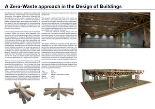
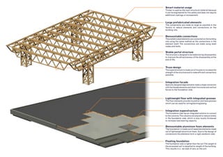
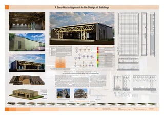
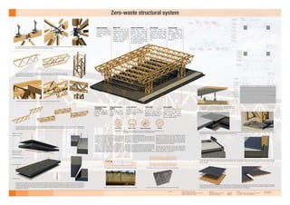
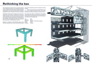
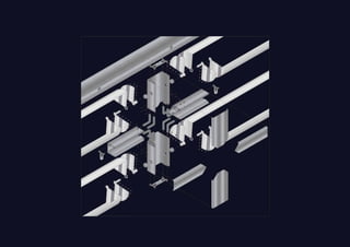
ir. Robert van Houten
Portfolio
2014 - 2016 		 Delft University ofTechnology
			Master BuildingTechnology, Sustainable Design Studio
				Graduated Cum Laude
				Grade: 8.5/10
2010-2014 		 Delft University ofTechnology
			Bachelor Architecture
				Grade: 8/10
				Minor: Architectural engineering
				 ‘Propedeuse in 1’ Cum Laude
09/2012 - 02/2013	 Delft University ofTechnology
			Minor Civil Engineering
2004-2010 		 Bonhoeffer College Enschede Bruggertstraat
			VWO+ Natuur enTechniek en Gezondheid,Technasium, Gymnasium
				grade: 7,5/10
Name:			 ir. Robert Sebastiaan van Houten
E-mail:			robertsvh@hotmail.com
Address:		 Balthasar van der Polweg 198
			2628AX Delft
Date of birth:		 11-08-1992
Summary
Objective
Education
Extracurricular activities
CurriculumVitae
ir. R.S. van Houten
			 Disciplined, ambitious, hard working, perfectionist, eager to learn
			Creative and analytic
			MSc BuildingTechnology
			 Making a difference in the world by innovation and technical design
2011 - present 		 RowingTalent Centre Zuid Holland & D.S.R. Proteus-Eretes
			Semi-professional rowing athlete
				6th at theWorld University Games 2014 in the coxless four
				 3rd in the Dutch National Championships 2014 under 23 in the coxless pair
				 Dutch National Champion 2013 under 23 in the coxless pair
2012 - 2015		 D.S.R. Proteus-Eretes
			Outdoor bar designer introduction weeks
				Responsible for design and construction of yearly small temporary outdoor bar
2011 - 2012		 D.S.R. Proteus-Eretes
			Member ‘Building committee’
				Responsible for setting up list of requirements
10/2015 - present	 Drafting Factory
			CAD designer
				2D floorplan drawings in AutoCad
11/2013 - 02/2014	 Ontwerpers ADAM
			CAD designer
				3D modelling in Google Sketch-up and 2D AutoCad drawings
Work experience
			 Creative and technical design skills
			Extensive computer knowledge
				Autodesk AutoCad
				Autodesk Rhinoceros + Grasshopper
				Autodesk 3DsMax +Vray
				Google Sketchup
				 Adobe Creative Suite - Photoshop, Indesign, Illustrator, Premiere
				 Microsoft Suite -Word, Excel, Powerpoint
			Languages
				 Dutch 		 (native proficiency)
				English 	(full professional proficiency)
				German 	(limited working proficiency)
			Public speaking skills
			Rowing
			Skyscrapers
			Reading
			Fitness
			Cycling
			Science&Technology
			Psychology&Philosophy
Skills
Interests
STUDY PROJECTS
This part showcases my most interesting projects during my study at the University
ofTechnology Delft.
A Zero-Waste approach in the Design of Buildings
This project is the result of a graduation project at the
Delft University of Technology in the studio Building
Technology of the Master Architecture, Urbanism and
Building Sciences.The project is a cooperative effort of
two graduation students.This cooperation allowed for a
greater scope and depth of the project and research. In
this research I was fully responsible for the load bearing
structure and foundation design.The main research towards
zero-waste was done in cooperation. Next follows the
abstract of the research.
Climate change and environmental issues are important
in today’s society. The earth is being depleted of its
resources and the changing climate could irreversibly
change the planet for the worse. Sustainable buildings
are mostly optimised for the use phase but neglect end
of life scenarios. Buildings are often demolished and
materials are dumped on a landfill. In a world where climate
change and resource depletion is a pressing issue this is
not acceptable. Buildings should be designed and made
in such a fashion that allows for reuse and recycling of
materials. Currently there is no suitable method available
to design or to assess a building for this aspect.This
research presents a method that increases focus on
the end of life of buildings: zero-waste designing.The
goal of this study is to assess a zero-waste approach
on practical application on a design and its process.
The main research question of this study is how a building
can be designed to generate no waste in all phases of its
construction and demolition.This is divided into three
sub-questions: What are the principles and functional
requirements of a zero-waste building design?What are
important factors in realising a zero-waste building design?
What is a possible design solution for an industrial building
according to zero-waste principles and requirements?
These questions are answered using a mixed approach of
research and design.The specific demands, requirements
and tips of zero-waste are compiled and then applied on
a conceptual design.An industrial building is used as an
example case to answer the questions from a practical
perspective.
The research concludes that three main points are
important in a zero-waste design. Firstly, no waste may
be produced during any phase of the life of the building.
Secondly, every material used in the building should remain
in its respective material cycle during its life cycle.Third,
reuse of materials should be made possible in such a way
that invested/embodied energy is maintained as much
as possible or can easily be increased.
	 From the industrial building design case the
following was concluded:The overall design realises a
zero-waste design by using the right materials and by
maximising the attractiveness of disassembly at the end
of life of the building by appropriate detailing and system
choice.
The design method as proposed can be difficult to
implement fully on every building design. Overall it will
be difficult to put a zero-waste approach in practice in the
building industry to solve the pressing issues regarding
the environment.A change of mind-set is necessary.The
implementation of the proposed zero-waste method will
also require an infrastructure that is not yet available.
Some solutions in the design test case are unproven or
uneconomical compared to conventional designs.This
may lead to the design not being feasible to construct.
It can be concluded that designing buildings to produce
zero-waste at the end of life is possible, however more
research will be required to also make it feasible and to
prove the proposed solutions.
Year:		 2016
Language:	English
Course:	 Master - Graduation project
Grade:		 8.5/10
Duration:	 1 year
Stable portal structure
The structure is designed to be stable during (dis)assembly
to improve the attractiveness of the disassembly at the
end of life.
Demountable connections
The prefabricated elements are connected on the building
site using the same method as the connections in the
element itself. The connections are made using steel
nodes and bolts.
Smart material usage
Timber is used as the main structural material because
it can be engineered for fire safety and does not require
additional coatings or encasement.
Large prefabricated elements
The components are made as large as possible in the
factory to reduce elements and connections on the
building site.
Truss design
The superstructure is made out of trusses to increase the
strength of the structure and to make efficient connections
possible.
Demountable aluminium foam elements
The foundation is made out of separate elements made
out of lightweight aluminium foam. Due to the design of
connections the elements form a rigid sandwich slab.
Integration superstructure
The foundation slab has an integrated solution to connect
to the columns.The columns are placed to reduce stress
in the foundation slab, which is also locally thickened
to increase load bearing capacity.
Integration facade
Specially designed edge elements make a shape connection
with the facade elements and divert horizontal and vertical
forces to the foundation slab.
Lightweight floor with integrated grooves
The floor elements provide insulation and have grooves
which can be used for wiring/ducting/piping.
Floating foundation
The foundation slab is lighter than the soil.The weight of
the excavated soil is equalled to weight of the building.
This results in a net load of zero on the soil.
Delft University of Technology
Faculty of Architecture and the built environment
Master track Building Technology
5-4-2016 Students:
Robert Sebastiaan van Houten - 4063570
Nick Anthony de Lange - 4092813
Mentors:
ir. Frank R. Schnater - Chair of Design of Construction
ir. Joris Smits - Chair of Structural Design
External examiner:
ir. Robert Nottrot
Overview of the zero-waste design process.
Functional
requirements
Integrated design
Appropriate materials Appropriate connections ConstructionAppropriate systems
+
Zero-waste
requirements
Deconstruction
Appropriate materials
Zero-waste
assessment
Importance
Relation to
primary
demand
number:
Used materials must come from a sustainable, reused source,
respecting embodied energy.
A sustainable source is defined as a way of gathering materials that can be continued
indefinitely. Respect towards embodied energy means energy used to produce a material
is not wasted.
2
No polluting, toxic or hazardous materials are used.
Dangerous materials are less likely to be reused, as special precautions should be taken for
safe handling of these materials, which are possibly not available or possible outside
production facilities. Moreover in the future these materials may not be used anymore.
1, 2
Used materials should be identifiable after the lifetime use in
a building or component to allow for reuse.
Without identification of the material it is difficult to reuse it. 2
The amount of different used materials should be kept to a
minimum.
If more materials are used it will become harder to separate them. The more difficult the
separation of materials is, the less likely it is that materials are reused.
1, 2
Inseparable connections should be avoided or made of the
same material.
Chemical bonds, if used, should be weaker than the materials
to be bonded, and should not be destructive towards the
materials when deconstructed.
Secondary finishes may only be used when it is easily
separable from the base material (and complies with all other
demands).
The amount of different connectors and connections should
be kept to a minimum.
The more connectors and connections are used the more difficult it is to take the building
apart. This increases the likelihood that taking the building apart is deemed too
unattractive and demolishment is a better option. This should be prevented.
1, 2
Joints, connectors and components have to withstand
repeated use to keep the materials in the highest possible
embodied energy state.
By making sure connections are made to withstand repeated use, they can be reused
more. In this way damage is less likely to occur, which could cause the component to be
wasted. This is not a hard demand when the materials of which the connection is made
can be recycled.
3
The amount of (different types of) components should be
minimised
More components and more types means a more complex building. This will decrease the
likelihood of disassembly as the complexity will increase cost and time of disassembly.
1
Provide permanent identification of component types
With proper identification of a component, it is clear what belongs to eachother. It will
prevent damage of functioning parts. It also helps in the reuse of components.
2, 3
Design for maximum standardization or repitition
Standardization and repitition will decrease the complexity of the design, which increases
the likelihood of disassembly. It also allows for more options of reuse.
3
Designing multi-functionable components integrating systems
Multi-funcationable components will reduce the total amount of components in the
design. It also reduces the problem of layering of materials.
3
The complete structure, connections and components should
be made in such a way that they are efficient demountable
without destructive methods to the materials and
components.
This demand is set to prevent damage to components and connections. When materials or
connections are damaged, reuse is less attractive. When reuse is not made attractive,
these materials and components are sooner considered useless and wasted. ‘Efficient to
demount’ is defined as disassembling the building in the minimal amount of time possible
using the least amount of effort.
1, 2, 3
Methods for (dis)assembly should be made clear
permanently.
When the correct method for disassembly is not known, demolishment and waste
generation is possible to occur, as it can be seen as the more simple solution.
1, 3
The hierarchy of the building should be such that it is in
relation to the expected lifespan of the parts.
This demand prevents unnessary actions to remove or replace certain parts of the
building, making it more attractive to dissassemble without destructive methods.
1
Means of handling and locating components during the
assembly and disassembly procedure should be provided.
When manoeuvring a building element or component is difficult to do because of lack of
means of handling, the option to demolish rather than disassemble might sooner be
taken, generating waste.
1
No specialized tools should have to be developed or used for
(dis)assembling the building.
Specialized tools might not be available when disassembling a building. When these tools
are required but not available, the option to demolish the building, generating waste,
might sooner be taken.
1
Modularity and an open building system should be used.
If components and parts are easily used in other buildings, it is more attractive to
disassemble a building at the end of life.
1, 3
Access to all parts of the building and to all components
should be provided.
If all parts can be easily reached without destructive methods, it will prevent the
generation of waste and increase the likelihood of deconstruction and reuse
1, 3
Most reusable parts should be the most accessible.
When the most reusable parts are the most accessible, these parts will more likely be
reused as compared when they are less accessible. This also helps that the initiative to
demount rather than to demolish the building is more likely to be taken.
1, 3
The system designed should be able to be prefabricated.
Prefabrication can help in making the building more simple to demount and to be reused,
as similar processes, (but reversed) can be used to take the building(-elements) apart, with
the advantage of a clean factory environment and less time on the building site. However
prefabrication does not necessarily mean a building can be demounted easily.
1, 2
1, 2
Inseparable connections can by definition not be separated into its components.
Therefore reuse is made difficult, and it is likely that it generates waste.
Zero Waste secondary demands
Materials
Connections
Assembly and disassembly
Components
List of secondary demands per category.
Construction order Deconstruction order
Simple geometric shape
Minimal number and types of
connections and components by
using a box shape for the building
Superstructure design
Façade design
Foundation design
250064026502650230
F2.a
F1.a
F2.a
F1.b
D4
Detail number
Author
Scale
Location/name
Zero-Waste Industrial building Graduation Project
Design part Facade
1:50
N. A. de Lange
Close up sections
-
Detail number
Author
Scale
Location/name
Zero-Waste Industrial building Graduation Project
Design part Structural
1:50
R.S. van Houten
Sections
-
85141293
B'B
86361556
A'
A
A Zero-Waste Approach in the Design of Buildings
Introducing a new way of approaching sustainability in buildings
with a conceptual industrial building design as an illustrative example.
1 Starting/final situation4 Placement/removal of first layer of
aluminium foam for column support
10 Installation/removal of column components13
Placement/removal of truss assemblies
between space-trusses
Deconstruction order
7 Installation/removal of top layer of
foundation slab and foundation edge
3 Placement/removal of bottom
part column connection
6 Installation/removal of bottom
layer of foundation slab
12
Placement/removal of mid section
component of space-truss assembly
15 Placement/removal of wall components
Construction order
9 Placement/removal of floor components 2 Landscaping of foundation footprint5 Placement/removal of second layer
of aluminium foam under column
11
Placement/removal of end
components of space-truss assembly
14 Installation/removal of roof components
Placement/removal of top part
column connection
8
1960
1970
1980
1990
2000
2010
2020
2030
2040
2050
2060
2070
2080
2090
2100
50
100
150
200
250
300
350
400
0
Amount extracted
Amount left
YEARS
BILLIONTONNES
Depletion of bauxite
Materials
Construction Demolition Waste
Deconstruction
Zero-waste
requirements
Design
Functional
requirements
Appropriate materials
ConstructionDesign
Functional
requirements
+
Diagram of the Delft Ladder showing a ranked list of end of life scenarios for
buildings. For zero-waste only those above useful application can be used.
The primary zero-waste demands.
Prevention
Construction reuse
Element reuse
Material reuse
Useful application
Immobilisation with useful application
Immobilisation
Incineration with energy recovery
Incineration
Landfill
Large amounts of waste and debris are currently produced by
the building industry worldwide. The lack of reuse and proper
recycling in the building industry will lead to resource depletion
and a waste of energy. New materials need to be extracted
and produced, which requires energy, while used materials are
dumped or incinerated. The energy required will also produce
greenhouse gasses, as most of the energy production is still
based on fossil fuels.
Moreover the resources of the earth are limited and with
an expected growth in population and prosperity it will become
unsustainable to dispose materials in landfills or incinerators.
When buildings would be designed according to a zero-waste
approach, this problem could hypothetically be solved.
Buildings should be designed and made in such a fashion
that allows for reuse and recycling of materials. Waste production
at the end of life of a building should not be tolerated. Currently,
there is no suitable method available to design or to assess a
building for this aspect.
This design realises a zero-waste ideal. This building design case
is an exemplary design for future buildings and concentrates on
closing material cycles at the end of life of buildings. Disassembly
is taken as the main concept for the design and is the leitmotif
for the final building. This has led to a unique and revolutionary
design solution: a building which results in zero-waste at the end
of life. This allows for a fully closed cycle of building materials
and resources.
The building is completely demountable and can be
disassembled efficiently without destructive methods. Each
component is assembled to another using simple mechanical
connections making full use of demountable connections. Every
component used in the building is made out of fully recyclable
or renewable materials.
The entire building has been optimised to reduce the total
amount of connections and total amount of elements. This is
done to increase the efficiency of demountability of the building.
The philosophy of this concept is to increase the likeability
of disassembly at the end of life of the building. The building
therefore does also not require special tools or transportation to
disassemble the components.
The final design of the building is a box shaped structure
with a size of 45x99m with an approximate height of 10,2m.
The interior free height is 6m. The columns are positioned
8,23m inwards from the exterior walls and spaced 22,5m apart.
In the longitudinal direction the columns are spaced 24m apart.
Besides from the columns the building is one large open space.
Within this space the machinery, processing lines and storages
as required by the program can be arranged freely.
Conventional end of life solution of a building
Waste is heterogeneous mix of materials which
can not be reused or recycled
Delft University of Technology
Faculty of Architecture and the built environment
Master track Building Technology
5-4-2016 Students:
Robert Sebastiaan van Houten - 4063570
Nick Anthony de Lange - 4092813
Mentors:
ir. Frank R. Schnater - Chair of Design of Construction
ir. Joris Smits - Chair of Structural Design
External examiner:
ir. Robert Nottrot
System choice ElementsMaterial choice Design of connections
System choice, material choice and the design of connections are important for zero-waste. Next to this, a
zero-waste foundation will always consist out of separate elements.
Zero-waste structural system
The load bearing structure is designed from timber. The
predictable charring rate of the timber is used to protect the
structure from fire. The increasing temperature does not effect
the strength of the timber and the charring rate can be used to
calculate a period of time in which the structure remains safe.
No additional fire protection is required.
The superstructure is designed to reduce the total
amount of elements and connections on the building site to
increase the efficiency of (dis)assembly. Steel nodes and bolts
are used to connect the timber elements together to form
prefabricated components. These are then further assembled
on the building site using the same type of connection. The size
of the prefabricated elements is based on the maximum size of
a normal truck to avoid special transports.
The superstructure is designed for efficient (dis)assembly, which
also takes stability into consideration. The space-truss forms a
stable portal in combination with the columns. The columns and
the space-truss parts are also stable on their own and do not
require temporary bracing.
The design utilises a floating foundation. The total weight of the
building is equalled by the weight of the soil that is excavated
from the building site. The stress on the soil will thus remain the
same as prior to construction which will prevent settling of the
building and provide the necessary load bearing capacity.
The floating foundation will be made out of demountable
elements. The elements are made from a lightweight material
but is strong in compression: aluminium foam. The slab is
designed as a sandwich structure which is strong enough to
handle the internal moments caused by the columns and other
loads. The elements are connected together to form a rigid slab
to avoid settling of individual elements and to increase the total
load bearing capacity of the foundation.
The total structure design thus consists out of demountable
elements made from recyclable or renewable materials. The
amount of total elements and connections are minimised to
increase the efficiency of disassembly. All this makes the
structural design a zero-waste solution.
Integrated facade
connection
Connection to the
facade is integrated
into the foundation
design.
Lightweight
The foundation is designed
to ‘float’ on the soil and is
therefore made using a
lightweight structure of an
aluminium foam sandwich.
Demountable
Thefoundationcomponentsare
securedusingbolts,makingita
demountable foundation slab.
Shape connections provide
the structural connections
between the elements.
Demountable
Large prefabricated
elements allow for
fast (dis)assembly on
the building site using
a minimum amount
of connections and
elements
Safe in fire
Timber is used for the
superstructure as it can be
engineered for fire safety
using the predictable
charring rate. No additional
coatings or protection is
required, and timber is a
renewable material.
Smart connections
Steel nodes are used to
provide the connection
between timber elements
and components. Only
a small amount of bolts
are required because the
connections are designed to
be pinned and do not need
to transfer moments.
Truss design
By using trusses the
connections can be made
pinned and allow for large
spanning elements. Both
reduce the amount of
connections on the building
site
Stable elements
The column and space-
truss form a stable portal
and require no additional
bracing during (dis)
assembly
Large elements
To reduce the number of
elements in the foundation,
the components are made as
large as possible
Integrated climate
system
The climate system
can be placed in the
gutters in the floor
panels.
Aluminium screw insert
Aluminium sheet
Positive stud shape
Aluminium sheet
Bolt with cork sealant
Negative stud shape
Cork sealant strip
Groove for sealant
The foundation consists out of two layers of aluminium foam elements which are designed to function as a sandwich structure. The outer layers of
the sandwich are aluminium sheets which are bonded to the aluminium foam during the foaming process, creating a metallic bond. The sheets are
connected between elements using a hook connection. The aluminium foam has integrated shear studs for mitigating shear forces, these also help
in the alignment of the elements. The elements are secured together with bolts. The placement of the top layer on the bottom layer is optimised for
reducing forces in the slab.
The floor element insulates the building from the foundation using a cork layer. Grooves are integrated into the cork to allow for piping and wiring. A steel plate is
welded onto a steel grate and inserted into the cork. The connection is friction based and the steel plate can be removed using the gaps integrated onto the side
of the element. The floor element also has integrated lifting holes to increase the efficiency of (dis)assembly.
The truss and space-truss consist out of parts which are assembled on the building site. This is necessary to avoid special transport. The space-truss
is a heavy and large element and by dividing it into sections the need of additional cranes or very large cranes is avoided. The parts can be joined
together using only a few bolt connections.
The weight of the soil excavated is equal to the total building weight
Timber has a predictable charring rate which can be used for fire safety
The foundation elements are connected rigidly to prevent deformation
Aluminium foam is used as a lightweight fill material for the foundation
The components are prefabricated into elements that fit onto regular trucks. The prefabrication reduces the
amount of connections that need to be made on the building site. It also allows for the reuse of the individual
timber elements in the total component.
The connections between the timber elements are made using steel nodes. The steel nodes are made out of steel plates which are welded together.
The timber elements have slots in which the nodes fit and are fastened with bolts.
The prefabricated elements are assembled on the building site using the steel nodes and bolts.
f t hi h bl d th b ildi it Thi i t id i l t t Th t
The roof is connected to the structure with a steel socket and transfers the
horizontal forces of the wind. The socket is connected rigidly to the truss.
The tube inserted into the socket is pinned to the roof.
The column connection to the foundation is made to transfer compressive and tensile forces. It also allows for adjustment of the position of the column. The steel
plates disperse the point load induced by the columns over a larger surface area.
The foundation edge element is designed to connect with the facade elements. The foundation supports the vertical load of the facade and the shape of the edge
element also secures the element in place and diverts the horizontal forces to the foundation. An aluminium sheet is integrated in the foam to reduce the total
stress on the foam.
ation elements are connected rigidly to prevent d
f i d li ht i ht fill t i l f th
SkeletOffshore
Insulation
Facade to floor fixing, also
add-on capability
Element to element
fixing
PV-panels
Corrugated alumini-
um sheet
Integrated aluminium
window frame, with tri-
ple glazing and integrated
shading
Corrugated alluminium
sheet, also used as air
duct in cold climate
Anodized aluminium
sheet
Polished aluminium
sheet
This assignment was accomodated by KeppelVerolme
BV. Current semi-submersible accomodations (Floatels)
are very energy consuming. In order to save on costs
KeppelVerolme BV asked to design a new accomodation
for 400 workers on top of a semi-submersible platform.
Every worker must be provided with his own cabin with
daylight acces.Along with building services, recreational
spaces and catering spaces were also needed.
This design proposes a solution that is lower in operation
costs (OPEX) and also lower in construction costs (CAPEX).
The building is made around a steel skeleton structure.
In contrary to conventional solutions, the steel skeleton
is warm and is bolted instead of welded.The structure
consists of columns and floor elements, which are rigidly
connected to provide stability.
The facade is made of corrugated aluminium sandwich
elements. These provide insulation for the structure.
The panels are connected to the structure using a bolt
connection.These connections also provide the opportunity
for add-ons if needed in the future. The cavity in the
corrugated plates is used to pre-heat the ventilation air.
The building is designed for repetition in order to save
costs in production and construction.
Year:		 2015
Language:	English
Course:	 Master - Extreme
Grade:		 9/10
Duration:	 10 weeks
ReSolver
The project was to design a new innovative sunshading
system.This design is based on a standard blind system.
But conventional blinds cover only part of the problems
related to sunshading and often block out all daylight
and the view. The ReSolver ocusses on three issues:
overheating, lack of daylight further away from the façade
and glare problems.
The goal of the reSOLver is to adress all these problems,
while maintaining visibility through the façade. In doing
so the reSOLver reduces the need for airconditioning and
artificial lighting and improves the quality of the indoor
space. By using circular blinds with a high-reflective
convex side and a diffuse-reflective concave side, the
design is able to:
•	 Selectively block out the sun, keeping the heat out
while maintaining visibility
•	 Redirect sunlight to the ceiling and further into the
room
•	 Prevent glare problems, without keeping the daylight
out
This project was done in a group of three students. I was
responsible for leading the team, structural calculations
and mechanical design, but heavy collaboration in the
team was most common.We also built a prototype and
subsequently tested the design.
Year:		 2014
Language:	English
Course:	 Master - Bucky Lab
Grade:		 9,5/10
Duration:	 10 weeks
reSOLver
A complete daylight management solution
Students:
Supervisor:
Course:
Kirolos Abdalla, Jeroen ter Haar, Robert van Houten
Dr.-Ing. Marcel Bilow
Bucky Lab Msc 1
Redirecting the light to the
ceiling & into the room
Selectively blocking out the
sun’s rays
Preventing glare, but still
using the sunlight
The reSOLver concept focusses on three issues
regarding the sun and daylight: overheating,
lack of daylight further away from the façade
and glare problems. Most existing solutions,
like window blinds, cover only part of these
problems and block out all daylight and the
view.
The goal of the reSOLver is to adress all
these problems, while maintaining visibility
through the façade. By using circular blinds
with a high-reflective convex side and a
diffuse-reflective concave side, the reSOLver
can:
• Selectively block out the sun, keeping
the heat out while maintaining visibility
• Redirect sunlight to the ceiling and
further into the room
• Prevent glare problems, without
keeping the daylight out
By doing so the reSOLver reduces the need
for airconditioning and artificial lighting and
improves the quality of the indoor space.
Inactive position, minimal
obstruction
Fully blinded facade
Both blinds are turned towards the sun Only inner blind is turned to change
the configuration
Rethinking the box
This is a design for a pavilion which can travel around the
world.Therefore this design can be adopted to different
climate conditions.The most extreme cases,Amsterdam
and Singapore, were taken as a benchmark.The design
integrates structural, climate and constructional design.
The design is optimized for transport and construction
speed.The main structure is inspired by construction
cranes and stage construction.The building is suspended
on four massive trusses, supported by four mega columns.
The building is constructed in reverse order, first the top
then the bottom. No additional cranes are required as
the structure can lift itself along its columns.
Climate is controlled in three different zones: a fully
mechanical operated zone, a natural ventilated and heated
zone and an intermediate zone with no additional climate
systems.
	 Other interesting features are the ETFE-foil outer
skin, which is zipped into place. And the media-mesh,
allowing the building to be used as a massive screen.
This project was made in collaboration with another
student. My task was focused on the structural integrity of
the superstructure and substructure, the climate system,
calculations and the design plan.
Year:		 2013
Language:	Dutch
Course:	 Bachelor - Renzo Piano project
Grade:		 8,5/10
Duration:	 6 weeks
ROWING
During my study I started rowing.This became a big part of my life as it developed
into a semi-professional rowing career. In this section I will elaborate on how
rowing on this level influenced my life.
2010-2011
	 Best Freshmen’s Eight
	 Kings of Sprint
2012-2013
	 Minor at RowingTalent Centre Zuid-Holland
	 National Champion U23 coxless pair
	 Part of selection U23 mens eight
2013-2014
	 Major at RowingTalent Centre Zuid-Holland
	 Part of selection U23 mens eight
	 National Student Champion coxless four
	 6th at FISU StudentWorld Championships 		
	 in the coxless four
My rowing career started in 2010, at the same time I was
starting my study at the University ofTechnology Delft.
I joined the D.S.R. Proteus-Eretes. I was selected for
the freshmen’s eight and that became a very succesful
year.Then I decided to continue rowing.
The training regime for rowing is particulary tough. It
requires a lot of time, training between 9 to 12 times a
week.Which is roughly 25 hours. Next to this I have to
sleep 8 hours each night, pay great attention to my diet
and restrain from alcohol and alike.
I combine my study with rowing, which is in essence
combining two full time jobs. It requires discipline and
planning in order to be succesful in both. Rowing makes
you an excellent team-worker and it also teaches you
that diligence is rewarded.
PERSONAL PROJECTS
The following pages show some highlights of my personal projects
Outdoor Bar
This project is dedicated to the introduction week of the
University ofTechnology Delft. In this week new students
can orientate on the different student associations.The
rowing club participates in this event in order to attract
new members in combination with organised events.
The platform is therefore transformed into the event
stage. One of the ideas was to create an outdoor bar to
facilitate the people on the platform with drinks.
I was responsible for designing and building this bar
over three consecutive years. Each year the bar became
bigger because of the success in the previous year.The
first two designs were circular in shape and set up as a
free standing structure on the platform.The third design
needed to be even bigger and allow for more space on
the platform.This bar is thus constructed underneath
the balcony of the society building.
The outdoor bar is constructed using old pallet wood.
Each bar design was created in modules. The modules
were between 1,5m and 2m in length.The modules existed
of a portal frame with a closed lower section. On top of
the closed section the bar is constructed. In the first two
design the modules are set up in a hexagon.The third
design traces the outline of the balcony.
The roof is constructed with beams and provide the
stability for the structure. In the circular designs the
structure stands autonomous, the third design is stabilized
with the balcony as support.The roof is finished with a
plastic sheet and covered with old reed fences.The bar
is further decorated with lights and old wooden oars.
The structure was sanded down for comfortable use.
Miniature Modeling
This is a hobby I developed in my high school years. It is
a tabletop strategy battle-game based onThe Lord of the
Rings.The game is played with dice and each model has
its own rules.The game is similar to the board game Risk.
The models are made in plastic or tin and can be bought.
The models come in pieces and need to be assembled
and painted. I also modified some of the models into
custom configurations.
As part of the game a board is required with scenery.The
scenery had to be made to match the scale of the miniature
models.The standard infantry model is around 2,5cm high.
The scenery I made vary from landscape features such
as hills, streams, rocky outcrops and buildings such as
houses, walls, fortifications and ruins.
I designed and built my own scenery from foam-board,
polystyrene and balsa-wood with basic equipment such
as an utility knife, saws and glue.When the structure was
finished I painted them in a base of texture paint.The
models are then completed using simple water based
paints.
PortfolioRSvanHouten_compressed

PortfolioRSvanHouten_compressed

  • 1.
    ir. Robert vanHouten Portfolio
  • 2.
    2014 - 2016 Delft University ofTechnology Master BuildingTechnology, Sustainable Design Studio Graduated Cum Laude Grade: 8.5/10 2010-2014 Delft University ofTechnology Bachelor Architecture Grade: 8/10 Minor: Architectural engineering ‘Propedeuse in 1’ Cum Laude 09/2012 - 02/2013 Delft University ofTechnology Minor Civil Engineering 2004-2010 Bonhoeffer College Enschede Bruggertstraat VWO+ Natuur enTechniek en Gezondheid,Technasium, Gymnasium grade: 7,5/10 Name: ir. Robert Sebastiaan van Houten E-mail: robertsvh@hotmail.com Address: Balthasar van der Polweg 198 2628AX Delft Date of birth: 11-08-1992 Summary Objective Education Extracurricular activities CurriculumVitae ir. R.S. van Houten Disciplined, ambitious, hard working, perfectionist, eager to learn Creative and analytic MSc BuildingTechnology Making a difference in the world by innovation and technical design 2011 - present RowingTalent Centre Zuid Holland & D.S.R. Proteus-Eretes Semi-professional rowing athlete 6th at theWorld University Games 2014 in the coxless four 3rd in the Dutch National Championships 2014 under 23 in the coxless pair Dutch National Champion 2013 under 23 in the coxless pair 2012 - 2015 D.S.R. Proteus-Eretes Outdoor bar designer introduction weeks Responsible for design and construction of yearly small temporary outdoor bar 2011 - 2012 D.S.R. Proteus-Eretes Member ‘Building committee’ Responsible for setting up list of requirements 10/2015 - present Drafting Factory CAD designer 2D floorplan drawings in AutoCad 11/2013 - 02/2014 Ontwerpers ADAM CAD designer 3D modelling in Google Sketch-up and 2D AutoCad drawings Work experience Creative and technical design skills Extensive computer knowledge Autodesk AutoCad Autodesk Rhinoceros + Grasshopper Autodesk 3DsMax +Vray Google Sketchup Adobe Creative Suite - Photoshop, Indesign, Illustrator, Premiere Microsoft Suite -Word, Excel, Powerpoint Languages Dutch (native proficiency) English (full professional proficiency) German (limited working proficiency) Public speaking skills Rowing Skyscrapers Reading Fitness Cycling Science&Technology Psychology&Philosophy Skills Interests
  • 3.
    STUDY PROJECTS This partshowcases my most interesting projects during my study at the University ofTechnology Delft.
  • 4.
    A Zero-Waste approachin the Design of Buildings This project is the result of a graduation project at the Delft University of Technology in the studio Building Technology of the Master Architecture, Urbanism and Building Sciences.The project is a cooperative effort of two graduation students.This cooperation allowed for a greater scope and depth of the project and research. In this research I was fully responsible for the load bearing structure and foundation design.The main research towards zero-waste was done in cooperation. Next follows the abstract of the research. Climate change and environmental issues are important in today’s society. The earth is being depleted of its resources and the changing climate could irreversibly change the planet for the worse. Sustainable buildings are mostly optimised for the use phase but neglect end of life scenarios. Buildings are often demolished and materials are dumped on a landfill. In a world where climate change and resource depletion is a pressing issue this is not acceptable. Buildings should be designed and made in such a fashion that allows for reuse and recycling of materials. Currently there is no suitable method available to design or to assess a building for this aspect.This research presents a method that increases focus on the end of life of buildings: zero-waste designing.The goal of this study is to assess a zero-waste approach on practical application on a design and its process. The main research question of this study is how a building can be designed to generate no waste in all phases of its construction and demolition.This is divided into three sub-questions: What are the principles and functional requirements of a zero-waste building design?What are important factors in realising a zero-waste building design? What is a possible design solution for an industrial building according to zero-waste principles and requirements? These questions are answered using a mixed approach of research and design.The specific demands, requirements and tips of zero-waste are compiled and then applied on a conceptual design.An industrial building is used as an example case to answer the questions from a practical perspective. The research concludes that three main points are important in a zero-waste design. Firstly, no waste may be produced during any phase of the life of the building. Secondly, every material used in the building should remain in its respective material cycle during its life cycle.Third, reuse of materials should be made possible in such a way that invested/embodied energy is maintained as much as possible or can easily be increased. From the industrial building design case the following was concluded:The overall design realises a zero-waste design by using the right materials and by maximising the attractiveness of disassembly at the end of life of the building by appropriate detailing and system choice. The design method as proposed can be difficult to implement fully on every building design. Overall it will be difficult to put a zero-waste approach in practice in the building industry to solve the pressing issues regarding the environment.A change of mind-set is necessary.The implementation of the proposed zero-waste method will also require an infrastructure that is not yet available. Some solutions in the design test case are unproven or uneconomical compared to conventional designs.This may lead to the design not being feasible to construct. It can be concluded that designing buildings to produce zero-waste at the end of life is possible, however more research will be required to also make it feasible and to prove the proposed solutions. Year: 2016 Language: English Course: Master - Graduation project Grade: 8.5/10 Duration: 1 year
  • 5.
    Stable portal structure Thestructure is designed to be stable during (dis)assembly to improve the attractiveness of the disassembly at the end of life. Demountable connections The prefabricated elements are connected on the building site using the same method as the connections in the element itself. The connections are made using steel nodes and bolts. Smart material usage Timber is used as the main structural material because it can be engineered for fire safety and does not require additional coatings or encasement. Large prefabricated elements The components are made as large as possible in the factory to reduce elements and connections on the building site. Truss design The superstructure is made out of trusses to increase the strength of the structure and to make efficient connections possible. Demountable aluminium foam elements The foundation is made out of separate elements made out of lightweight aluminium foam. Due to the design of connections the elements form a rigid sandwich slab. Integration superstructure The foundation slab has an integrated solution to connect to the columns.The columns are placed to reduce stress in the foundation slab, which is also locally thickened to increase load bearing capacity. Integration facade Specially designed edge elements make a shape connection with the facade elements and divert horizontal and vertical forces to the foundation slab. Lightweight floor with integrated grooves The floor elements provide insulation and have grooves which can be used for wiring/ducting/piping. Floating foundation The foundation slab is lighter than the soil.The weight of the excavated soil is equalled to weight of the building. This results in a net load of zero on the soil.
  • 6.
    Delft University ofTechnology Faculty of Architecture and the built environment Master track Building Technology 5-4-2016 Students: Robert Sebastiaan van Houten - 4063570 Nick Anthony de Lange - 4092813 Mentors: ir. Frank R. Schnater - Chair of Design of Construction ir. Joris Smits - Chair of Structural Design External examiner: ir. Robert Nottrot Overview of the zero-waste design process. Functional requirements Integrated design Appropriate materials Appropriate connections ConstructionAppropriate systems + Zero-waste requirements Deconstruction Appropriate materials Zero-waste assessment Importance Relation to primary demand number: Used materials must come from a sustainable, reused source, respecting embodied energy. A sustainable source is defined as a way of gathering materials that can be continued indefinitely. Respect towards embodied energy means energy used to produce a material is not wasted. 2 No polluting, toxic or hazardous materials are used. Dangerous materials are less likely to be reused, as special precautions should be taken for safe handling of these materials, which are possibly not available or possible outside production facilities. Moreover in the future these materials may not be used anymore. 1, 2 Used materials should be identifiable after the lifetime use in a building or component to allow for reuse. Without identification of the material it is difficult to reuse it. 2 The amount of different used materials should be kept to a minimum. If more materials are used it will become harder to separate them. The more difficult the separation of materials is, the less likely it is that materials are reused. 1, 2 Inseparable connections should be avoided or made of the same material. Chemical bonds, if used, should be weaker than the materials to be bonded, and should not be destructive towards the materials when deconstructed. Secondary finishes may only be used when it is easily separable from the base material (and complies with all other demands). The amount of different connectors and connections should be kept to a minimum. The more connectors and connections are used the more difficult it is to take the building apart. This increases the likelihood that taking the building apart is deemed too unattractive and demolishment is a better option. This should be prevented. 1, 2 Joints, connectors and components have to withstand repeated use to keep the materials in the highest possible embodied energy state. By making sure connections are made to withstand repeated use, they can be reused more. In this way damage is less likely to occur, which could cause the component to be wasted. This is not a hard demand when the materials of which the connection is made can be recycled. 3 The amount of (different types of) components should be minimised More components and more types means a more complex building. This will decrease the likelihood of disassembly as the complexity will increase cost and time of disassembly. 1 Provide permanent identification of component types With proper identification of a component, it is clear what belongs to eachother. It will prevent damage of functioning parts. It also helps in the reuse of components. 2, 3 Design for maximum standardization or repitition Standardization and repitition will decrease the complexity of the design, which increases the likelihood of disassembly. It also allows for more options of reuse. 3 Designing multi-functionable components integrating systems Multi-funcationable components will reduce the total amount of components in the design. It also reduces the problem of layering of materials. 3 The complete structure, connections and components should be made in such a way that they are efficient demountable without destructive methods to the materials and components. This demand is set to prevent damage to components and connections. When materials or connections are damaged, reuse is less attractive. When reuse is not made attractive, these materials and components are sooner considered useless and wasted. ‘Efficient to demount’ is defined as disassembling the building in the minimal amount of time possible using the least amount of effort. 1, 2, 3 Methods for (dis)assembly should be made clear permanently. When the correct method for disassembly is not known, demolishment and waste generation is possible to occur, as it can be seen as the more simple solution. 1, 3 The hierarchy of the building should be such that it is in relation to the expected lifespan of the parts. This demand prevents unnessary actions to remove or replace certain parts of the building, making it more attractive to dissassemble without destructive methods. 1 Means of handling and locating components during the assembly and disassembly procedure should be provided. When manoeuvring a building element or component is difficult to do because of lack of means of handling, the option to demolish rather than disassemble might sooner be taken, generating waste. 1 No specialized tools should have to be developed or used for (dis)assembling the building. Specialized tools might not be available when disassembling a building. When these tools are required but not available, the option to demolish the building, generating waste, might sooner be taken. 1 Modularity and an open building system should be used. If components and parts are easily used in other buildings, it is more attractive to disassemble a building at the end of life. 1, 3 Access to all parts of the building and to all components should be provided. If all parts can be easily reached without destructive methods, it will prevent the generation of waste and increase the likelihood of deconstruction and reuse 1, 3 Most reusable parts should be the most accessible. When the most reusable parts are the most accessible, these parts will more likely be reused as compared when they are less accessible. This also helps that the initiative to demount rather than to demolish the building is more likely to be taken. 1, 3 The system designed should be able to be prefabricated. Prefabrication can help in making the building more simple to demount and to be reused, as similar processes, (but reversed) can be used to take the building(-elements) apart, with the advantage of a clean factory environment and less time on the building site. However prefabrication does not necessarily mean a building can be demounted easily. 1, 2 1, 2 Inseparable connections can by definition not be separated into its components. Therefore reuse is made difficult, and it is likely that it generates waste. Zero Waste secondary demands Materials Connections Assembly and disassembly Components List of secondary demands per category. Construction order Deconstruction order Simple geometric shape Minimal number and types of connections and components by using a box shape for the building Superstructure design Façade design Foundation design 250064026502650230 F2.a F1.a F2.a F1.b D4 Detail number Author Scale Location/name Zero-Waste Industrial building Graduation Project Design part Facade 1:50 N. A. de Lange Close up sections - Detail number Author Scale Location/name Zero-Waste Industrial building Graduation Project Design part Structural 1:50 R.S. van Houten Sections - 85141293 B'B 86361556 A' A A Zero-Waste Approach in the Design of Buildings Introducing a new way of approaching sustainability in buildings with a conceptual industrial building design as an illustrative example. 1 Starting/final situation4 Placement/removal of first layer of aluminium foam for column support 10 Installation/removal of column components13 Placement/removal of truss assemblies between space-trusses Deconstruction order 7 Installation/removal of top layer of foundation slab and foundation edge 3 Placement/removal of bottom part column connection 6 Installation/removal of bottom layer of foundation slab 12 Placement/removal of mid section component of space-truss assembly 15 Placement/removal of wall components Construction order 9 Placement/removal of floor components 2 Landscaping of foundation footprint5 Placement/removal of second layer of aluminium foam under column 11 Placement/removal of end components of space-truss assembly 14 Installation/removal of roof components Placement/removal of top part column connection 8 1960 1970 1980 1990 2000 2010 2020 2030 2040 2050 2060 2070 2080 2090 2100 50 100 150 200 250 300 350 400 0 Amount extracted Amount left YEARS BILLIONTONNES Depletion of bauxite Materials Construction Demolition Waste Deconstruction Zero-waste requirements Design Functional requirements Appropriate materials ConstructionDesign Functional requirements + Diagram of the Delft Ladder showing a ranked list of end of life scenarios for buildings. For zero-waste only those above useful application can be used. The primary zero-waste demands. Prevention Construction reuse Element reuse Material reuse Useful application Immobilisation with useful application Immobilisation Incineration with energy recovery Incineration Landfill Large amounts of waste and debris are currently produced by the building industry worldwide. The lack of reuse and proper recycling in the building industry will lead to resource depletion and a waste of energy. New materials need to be extracted and produced, which requires energy, while used materials are dumped or incinerated. The energy required will also produce greenhouse gasses, as most of the energy production is still based on fossil fuels. Moreover the resources of the earth are limited and with an expected growth in population and prosperity it will become unsustainable to dispose materials in landfills or incinerators. When buildings would be designed according to a zero-waste approach, this problem could hypothetically be solved. Buildings should be designed and made in such a fashion that allows for reuse and recycling of materials. Waste production at the end of life of a building should not be tolerated. Currently, there is no suitable method available to design or to assess a building for this aspect. This design realises a zero-waste ideal. This building design case is an exemplary design for future buildings and concentrates on closing material cycles at the end of life of buildings. Disassembly is taken as the main concept for the design and is the leitmotif for the final building. This has led to a unique and revolutionary design solution: a building which results in zero-waste at the end of life. This allows for a fully closed cycle of building materials and resources. The building is completely demountable and can be disassembled efficiently without destructive methods. Each component is assembled to another using simple mechanical connections making full use of demountable connections. Every component used in the building is made out of fully recyclable or renewable materials. The entire building has been optimised to reduce the total amount of connections and total amount of elements. This is done to increase the efficiency of demountability of the building. The philosophy of this concept is to increase the likeability of disassembly at the end of life of the building. The building therefore does also not require special tools or transportation to disassemble the components. The final design of the building is a box shaped structure with a size of 45x99m with an approximate height of 10,2m. The interior free height is 6m. The columns are positioned 8,23m inwards from the exterior walls and spaced 22,5m apart. In the longitudinal direction the columns are spaced 24m apart. Besides from the columns the building is one large open space. Within this space the machinery, processing lines and storages as required by the program can be arranged freely. Conventional end of life solution of a building Waste is heterogeneous mix of materials which can not be reused or recycled
  • 7.
    Delft University ofTechnology Faculty of Architecture and the built environment Master track Building Technology 5-4-2016 Students: Robert Sebastiaan van Houten - 4063570 Nick Anthony de Lange - 4092813 Mentors: ir. Frank R. Schnater - Chair of Design of Construction ir. Joris Smits - Chair of Structural Design External examiner: ir. Robert Nottrot System choice ElementsMaterial choice Design of connections System choice, material choice and the design of connections are important for zero-waste. Next to this, a zero-waste foundation will always consist out of separate elements. Zero-waste structural system The load bearing structure is designed from timber. The predictable charring rate of the timber is used to protect the structure from fire. The increasing temperature does not effect the strength of the timber and the charring rate can be used to calculate a period of time in which the structure remains safe. No additional fire protection is required. The superstructure is designed to reduce the total amount of elements and connections on the building site to increase the efficiency of (dis)assembly. Steel nodes and bolts are used to connect the timber elements together to form prefabricated components. These are then further assembled on the building site using the same type of connection. The size of the prefabricated elements is based on the maximum size of a normal truck to avoid special transports. The superstructure is designed for efficient (dis)assembly, which also takes stability into consideration. The space-truss forms a stable portal in combination with the columns. The columns and the space-truss parts are also stable on their own and do not require temporary bracing. The design utilises a floating foundation. The total weight of the building is equalled by the weight of the soil that is excavated from the building site. The stress on the soil will thus remain the same as prior to construction which will prevent settling of the building and provide the necessary load bearing capacity. The floating foundation will be made out of demountable elements. The elements are made from a lightweight material but is strong in compression: aluminium foam. The slab is designed as a sandwich structure which is strong enough to handle the internal moments caused by the columns and other loads. The elements are connected together to form a rigid slab to avoid settling of individual elements and to increase the total load bearing capacity of the foundation. The total structure design thus consists out of demountable elements made from recyclable or renewable materials. The amount of total elements and connections are minimised to increase the efficiency of disassembly. All this makes the structural design a zero-waste solution. Integrated facade connection Connection to the facade is integrated into the foundation design. Lightweight The foundation is designed to ‘float’ on the soil and is therefore made using a lightweight structure of an aluminium foam sandwich. Demountable Thefoundationcomponentsare securedusingbolts,makingita demountable foundation slab. Shape connections provide the structural connections between the elements. Demountable Large prefabricated elements allow for fast (dis)assembly on the building site using a minimum amount of connections and elements Safe in fire Timber is used for the superstructure as it can be engineered for fire safety using the predictable charring rate. No additional coatings or protection is required, and timber is a renewable material. Smart connections Steel nodes are used to provide the connection between timber elements and components. Only a small amount of bolts are required because the connections are designed to be pinned and do not need to transfer moments. Truss design By using trusses the connections can be made pinned and allow for large spanning elements. Both reduce the amount of connections on the building site Stable elements The column and space- truss form a stable portal and require no additional bracing during (dis) assembly Large elements To reduce the number of elements in the foundation, the components are made as large as possible Integrated climate system The climate system can be placed in the gutters in the floor panels. Aluminium screw insert Aluminium sheet Positive stud shape Aluminium sheet Bolt with cork sealant Negative stud shape Cork sealant strip Groove for sealant The foundation consists out of two layers of aluminium foam elements which are designed to function as a sandwich structure. The outer layers of the sandwich are aluminium sheets which are bonded to the aluminium foam during the foaming process, creating a metallic bond. The sheets are connected between elements using a hook connection. The aluminium foam has integrated shear studs for mitigating shear forces, these also help in the alignment of the elements. The elements are secured together with bolts. The placement of the top layer on the bottom layer is optimised for reducing forces in the slab. The floor element insulates the building from the foundation using a cork layer. Grooves are integrated into the cork to allow for piping and wiring. A steel plate is welded onto a steel grate and inserted into the cork. The connection is friction based and the steel plate can be removed using the gaps integrated onto the side of the element. The floor element also has integrated lifting holes to increase the efficiency of (dis)assembly. The truss and space-truss consist out of parts which are assembled on the building site. This is necessary to avoid special transport. The space-truss is a heavy and large element and by dividing it into sections the need of additional cranes or very large cranes is avoided. The parts can be joined together using only a few bolt connections. The weight of the soil excavated is equal to the total building weight Timber has a predictable charring rate which can be used for fire safety The foundation elements are connected rigidly to prevent deformation Aluminium foam is used as a lightweight fill material for the foundation The components are prefabricated into elements that fit onto regular trucks. The prefabrication reduces the amount of connections that need to be made on the building site. It also allows for the reuse of the individual timber elements in the total component. The connections between the timber elements are made using steel nodes. The steel nodes are made out of steel plates which are welded together. The timber elements have slots in which the nodes fit and are fastened with bolts. The prefabricated elements are assembled on the building site using the steel nodes and bolts. f t hi h bl d th b ildi it Thi i t id i l t t Th t The roof is connected to the structure with a steel socket and transfers the horizontal forces of the wind. The socket is connected rigidly to the truss. The tube inserted into the socket is pinned to the roof. The column connection to the foundation is made to transfer compressive and tensile forces. It also allows for adjustment of the position of the column. The steel plates disperse the point load induced by the columns over a larger surface area. The foundation edge element is designed to connect with the facade elements. The foundation supports the vertical load of the facade and the shape of the edge element also secures the element in place and diverts the horizontal forces to the foundation. An aluminium sheet is integrated in the foam to reduce the total stress on the foam. ation elements are connected rigidly to prevent d f i d li ht i ht fill t i l f th
  • 8.
    SkeletOffshore Insulation Facade to floorfixing, also add-on capability Element to element fixing PV-panels Corrugated alumini- um sheet Integrated aluminium window frame, with tri- ple glazing and integrated shading Corrugated alluminium sheet, also used as air duct in cold climate Anodized aluminium sheet Polished aluminium sheet This assignment was accomodated by KeppelVerolme BV. Current semi-submersible accomodations (Floatels) are very energy consuming. In order to save on costs KeppelVerolme BV asked to design a new accomodation for 400 workers on top of a semi-submersible platform. Every worker must be provided with his own cabin with daylight acces.Along with building services, recreational spaces and catering spaces were also needed. This design proposes a solution that is lower in operation costs (OPEX) and also lower in construction costs (CAPEX). The building is made around a steel skeleton structure. In contrary to conventional solutions, the steel skeleton is warm and is bolted instead of welded.The structure consists of columns and floor elements, which are rigidly connected to provide stability. The facade is made of corrugated aluminium sandwich elements. These provide insulation for the structure. The panels are connected to the structure using a bolt connection.These connections also provide the opportunity for add-ons if needed in the future. The cavity in the corrugated plates is used to pre-heat the ventilation air. The building is designed for repetition in order to save costs in production and construction. Year: 2015 Language: English Course: Master - Extreme Grade: 9/10 Duration: 10 weeks
  • 10.
    ReSolver The project wasto design a new innovative sunshading system.This design is based on a standard blind system. But conventional blinds cover only part of the problems related to sunshading and often block out all daylight and the view. The ReSolver ocusses on three issues: overheating, lack of daylight further away from the façade and glare problems. The goal of the reSOLver is to adress all these problems, while maintaining visibility through the façade. In doing so the reSOLver reduces the need for airconditioning and artificial lighting and improves the quality of the indoor space. By using circular blinds with a high-reflective convex side and a diffuse-reflective concave side, the design is able to: • Selectively block out the sun, keeping the heat out while maintaining visibility • Redirect sunlight to the ceiling and further into the room • Prevent glare problems, without keeping the daylight out This project was done in a group of three students. I was responsible for leading the team, structural calculations and mechanical design, but heavy collaboration in the team was most common.We also built a prototype and subsequently tested the design. Year: 2014 Language: English Course: Master - Bucky Lab Grade: 9,5/10 Duration: 10 weeks
  • 11.
    reSOLver A complete daylightmanagement solution Students: Supervisor: Course: Kirolos Abdalla, Jeroen ter Haar, Robert van Houten Dr.-Ing. Marcel Bilow Bucky Lab Msc 1 Redirecting the light to the ceiling & into the room Selectively blocking out the sun’s rays Preventing glare, but still using the sunlight The reSOLver concept focusses on three issues regarding the sun and daylight: overheating, lack of daylight further away from the façade and glare problems. Most existing solutions, like window blinds, cover only part of these problems and block out all daylight and the view. The goal of the reSOLver is to adress all these problems, while maintaining visibility through the façade. By using circular blinds with a high-reflective convex side and a diffuse-reflective concave side, the reSOLver can: • Selectively block out the sun, keeping the heat out while maintaining visibility • Redirect sunlight to the ceiling and further into the room • Prevent glare problems, without keeping the daylight out By doing so the reSOLver reduces the need for airconditioning and artificial lighting and improves the quality of the indoor space. Inactive position, minimal obstruction Fully blinded facade Both blinds are turned towards the sun Only inner blind is turned to change the configuration
  • 12.
    Rethinking the box Thisis a design for a pavilion which can travel around the world.Therefore this design can be adopted to different climate conditions.The most extreme cases,Amsterdam and Singapore, were taken as a benchmark.The design integrates structural, climate and constructional design. The design is optimized for transport and construction speed.The main structure is inspired by construction cranes and stage construction.The building is suspended on four massive trusses, supported by four mega columns. The building is constructed in reverse order, first the top then the bottom. No additional cranes are required as the structure can lift itself along its columns. Climate is controlled in three different zones: a fully mechanical operated zone, a natural ventilated and heated zone and an intermediate zone with no additional climate systems. Other interesting features are the ETFE-foil outer skin, which is zipped into place. And the media-mesh, allowing the building to be used as a massive screen. This project was made in collaboration with another student. My task was focused on the structural integrity of the superstructure and substructure, the climate system, calculations and the design plan. Year: 2013 Language: Dutch Course: Bachelor - Renzo Piano project Grade: 8,5/10 Duration: 6 weeks
  • 14.
    ROWING During my studyI started rowing.This became a big part of my life as it developed into a semi-professional rowing career. In this section I will elaborate on how rowing on this level influenced my life.
  • 15.
    2010-2011 Best Freshmen’sEight Kings of Sprint 2012-2013 Minor at RowingTalent Centre Zuid-Holland National Champion U23 coxless pair Part of selection U23 mens eight 2013-2014 Major at RowingTalent Centre Zuid-Holland Part of selection U23 mens eight National Student Champion coxless four 6th at FISU StudentWorld Championships in the coxless four My rowing career started in 2010, at the same time I was starting my study at the University ofTechnology Delft. I joined the D.S.R. Proteus-Eretes. I was selected for the freshmen’s eight and that became a very succesful year.Then I decided to continue rowing. The training regime for rowing is particulary tough. It requires a lot of time, training between 9 to 12 times a week.Which is roughly 25 hours. Next to this I have to sleep 8 hours each night, pay great attention to my diet and restrain from alcohol and alike. I combine my study with rowing, which is in essence combining two full time jobs. It requires discipline and planning in order to be succesful in both. Rowing makes you an excellent team-worker and it also teaches you that diligence is rewarded.
  • 16.
    PERSONAL PROJECTS The followingpages show some highlights of my personal projects
  • 17.
    Outdoor Bar This projectis dedicated to the introduction week of the University ofTechnology Delft. In this week new students can orientate on the different student associations.The rowing club participates in this event in order to attract new members in combination with organised events. The platform is therefore transformed into the event stage. One of the ideas was to create an outdoor bar to facilitate the people on the platform with drinks. I was responsible for designing and building this bar over three consecutive years. Each year the bar became bigger because of the success in the previous year.The first two designs were circular in shape and set up as a free standing structure on the platform.The third design needed to be even bigger and allow for more space on the platform.This bar is thus constructed underneath the balcony of the society building. The outdoor bar is constructed using old pallet wood. Each bar design was created in modules. The modules were between 1,5m and 2m in length.The modules existed of a portal frame with a closed lower section. On top of the closed section the bar is constructed. In the first two design the modules are set up in a hexagon.The third design traces the outline of the balcony. The roof is constructed with beams and provide the stability for the structure. In the circular designs the structure stands autonomous, the third design is stabilized with the balcony as support.The roof is finished with a plastic sheet and covered with old reed fences.The bar is further decorated with lights and old wooden oars. The structure was sanded down for comfortable use.
  • 18.
    Miniature Modeling This isa hobby I developed in my high school years. It is a tabletop strategy battle-game based onThe Lord of the Rings.The game is played with dice and each model has its own rules.The game is similar to the board game Risk. The models are made in plastic or tin and can be bought. The models come in pieces and need to be assembled and painted. I also modified some of the models into custom configurations. As part of the game a board is required with scenery.The scenery had to be made to match the scale of the miniature models.The standard infantry model is around 2,5cm high. The scenery I made vary from landscape features such as hills, streams, rocky outcrops and buildings such as houses, walls, fortifications and ruins. I designed and built my own scenery from foam-board, polystyrene and balsa-wood with basic equipment such as an utility knife, saws and glue.When the structure was finished I painted them in a base of texture paint.The models are then completed using simple water based paints.