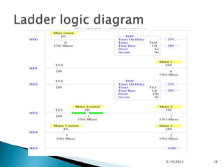
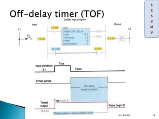
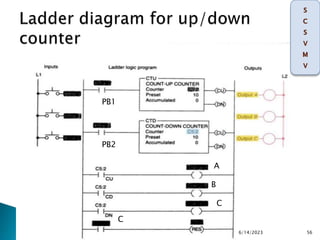
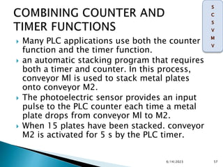
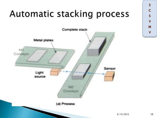
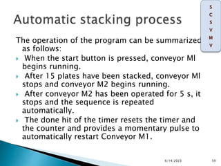
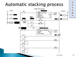
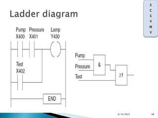
SlideShare a Scribd company logo
On delay timer,
OFF delay timer,
retentive timer instruction,
PLC counter Up and Down instructions,
Combining counter and timers,
simple application program using timer and counters ,
FBD concepts and programming
6/14/2023 1
 Timer is an instruction that waits a set
amount of time before doing something
(control time).
6/14/2023 2
 PLC timers are output instructions that provide
the same functions as mechanical timing
relays.
 They are used to activate or deactivate a device
after a preset interval of time.
 The preset time represents the time duration
for the timing circuit.
 The accumulated time represents the amount
of time that has elapsed from the moment the
timing coil became energized.
6/14/2023 3
 The advantage of PLC timers is that their
settings can be altered easily, or the number of
them used in a circuit can be increased or
decreased through the use of programming
changes rather than wiring changes.
 Another advantage of the PLC timer is that its
timer accuracy and repeatability are extremely
high since it is based on solid-state
technology.
6/14/2023 4
 On-Delay timer- simply “delays turning on”.
It is called TON
 Off-Delay timer- simply “delays turning off”.
It is called TOF
 Retentive or Accumulating timer- holds or
retains the current elapsed time when the
sensor turns off in mid-stream. It is called
RTO
6/14/2023 5
 A timer consists of an internal clock, a count
value register, and an accumulator. It is used
for or some timing purpose.
Clock
Accumulator
contact
reset
output
Register
Contact
6/14/2023 6
 Timers are output instructions that you can
condition with input instructions such as
examine if closed and examine if open.
 They time intervals as determined by your
application program logic.
 The on-delay timer operates such that when
the rung containing the timer is true, the
timer time-out period commences.
 At the end of the timer time-out period, an
output is made active.
6/14/2023 7
6/14/2023 8
6/14/2023 9
Enable (EN) bit
The enable bit is true (has a status of 1) whenever
the timer instruction is true.
When the timer instruction is false. The enable bit
is false (has a status of 0) .
Timer-timing (TI) bit
◦ The timer-timing bit is true whenever the accumulated
value of the timer is changing, which means the timer is
timing.
◦ When the timer is not timing, the accumulated value is not
changing. so the timer-timing bit is false.
Done (ON) bit
The done bit changes state whenever the
accumulated value reaches the preset value. its state
depends on the type of timer being used.
6/14/2023 10
Timer number
 This number must come from the timer file. In the example
shown. the timer number is T4:0. which represents timer file 4.
timer 0 in that 6le. There may be up to 1000 timers in each timer
file. Numbered from 0 through 999. The timer address must be
unique for this timer and may not be used for any other timer.
Time base
 The time base (which is always expressed in seconds) may be
either 1.0 s or 0.01 s. In the example shown, the time base is 1.0
s.
Preset value
 the preset value is 15. The timer preset value can range from 0
through 32,767.
Accumulated value
 the accumulated value is o. The timer's accumulated value
normally is entered as 0, although it is possible to enter a value
from 0 through 32,767
6/14/2023 11
 a series of motors can be started automatically with only
one start/stop control station.
 According to the relay ladder schematic, lube-oil pump
motor starter coil M1 is energized when the start
pushbutton PB2 is momentarily actuated.
 As a result,M1-1 control contact closes to seal in M1. and
the lube-oil pump motor starts.
 When the lube-oil pump builds up sufficient oil pressure.
the lube-oil pressure switch PS1 closes.
 This in turn energizes coil M2 to start the main drive
motor and energizes coil TD-1 to begin the time-delay
period.
 After the preset time-delay period of 15 s. 1 TD-l contact
closes to energize coil M3 and start the feed motor.
6/14/2023 12
6/14/2023 13
6/14/2023 14
 To write the ladder logic to control the
motors in section. The conditions are as
follows:
 Motor 1 should be turned ON after 5 seconds
the main switch has been switched ON.
 Motor 2 should be turned ON for 10 seconds
after Motor 1 s turned ON.
 Motor 3 should be turned ON after Motor 2 is
turned OFF.
6/14/2023 15
6/14/2023 16
 The off-delay timer (TOF) operation will keep
the output energized for a time period after
the rung containing the timer has gone false.
6/14/2023 17
6/14/2023 18
 If logic continuity is lost. the timer begins
counting time-based intervals until the
accumulated time equals the programmed preset
value.
 When the switch connected to input I:1.0/0 is
first closed, timed output 0 :2.0/1 is set to 1
immediately and the lamp is switched on.
 If this switch is now opened. logic continuity is
lost and the timer begins counting. After 15 s,
when the accumulated time equals the preset
time.
 the output is reset to 0 and the lamp switches
off. If logic continuity is gained before the timer
is timed out. The accumulated time is reset to O.
6/14/2023 19
 when power is first applied (limit switch LS1 open). Motor
starter coil M1 is energized and the green pilot light is on.
 At the same time, motor starter coil M2 is de-energized.
and the red pilot light is off.
 When limit switch LS1 closes. off-delay timer coil TD1
energizes.
 As a result, timed contact TD1-1 opens to de-energize
motor starter coil M1. timed contact TD1-2 closes to
energize motor starter coil M2.
 instantaneous contact T01-3 opens to switch the green
light off. and instantaneous contact TOI-4 closes to switch
the red light on.
 The circuit remains in this state as long as limit switch LSI
is closed.
6/14/2023 20
6/14/2023 21
6/14/2023 22
 When limit switch LSI is opened , the off delay
timer coil TD1 de-energizes.
 As a result, the time-delay period is started,
instantaneous contact TD1-3 closes to switch
the green light on, and instantaneous contact
TD1-4 opens to switch the red light off.
 After a 5-s time-delay period, timed contact
TD1-1 closes to energize motor starter MI.
and timed contact TD1-2 opens to de-
energize motor starter M2.
6/14/2023 23
 The process involves pumping fluid from tank A to
tank B. The operation of the process can be
described as follows:
 Before starting. PSI must be closed.
 When the start button is pushed. The pump starts.
The button can then be released and the pump
continues to operate.
 When the stop button is pushed. The pump stops.
 PS2 and PS3 must be closed 5s after the pump
starts. If either PS2 or PS3 opens. the pump will shut
off and will not be able to start again for another 14
s.
6/14/2023 24
6/14/2023 25
PS 1
STOP
PS2
PS3
 A retentive timer accumulates time whenever the
device receives power, and it maintains the
current time should power be removed from the
device.
 Once the device accumulates time equal to its
preset value. the contacts of the device change
state. to the device after reaching its preset value
does not affect the state of the contacts.
 The retentive timer must be intentionally reset
with a separate signal for the accumulated time
to be reset and for the contacts of the device to
return to their self state.
6/14/2023 26
 one major exception-a retentive timer reset (RES)
instruction. Unlike the TON, the RTO will hold its
accumulated value when the timer rung goes false
and will continue timing where it left off when the
timer rung goes true again. This timer must be
accompanied by a timer reset instruction to reset the
accumulated value of the timer to O.
 The RES instruction is the only automatic means of
resetting the accumulated value of a retentive timer.
 The RES instruction has the same address as the
timer it is to reset. Whenever the RES instruction is
true.
 both the timer accumulated value and the timer done
bit (ON) are rest to O .
6/14/2023 27
 PLC program for a retentive on-delay time along with a timing
chart for the circuit.
 The timer will start to time when time pushbutton PB1 is closed.
 If the pushbutton is opened 3 s, the timer accumulated value
stays at 3 s. When the time pushbutton is closed again, the timer
picks up the time at 3 S and continues timing.
 When the accumulated value equals the preset value, the timer
done bit T4 :2/DN is set to 1 and the pilot light output PL is
switched on.
 Because the retentive timer does not reset to 0 when the timer is
de-energized. the reset instruction RES must be used to reset
the timer.
 The RES instruction given the same address (T4:2) as the RTO.
When reset pushbutton PB2 closes. RES resets the accumulated
time to 0 and the ON bit to O. turning pilot light PL off.
6/14/2023 28
6/14/2023 29
6/14/2023 30
 A counter is set to some preset value and,
when this value of input pulses has been
received, it will operate its contacts.
 The counter accumulated value ONLY
changes at the off to on transition of the
pulse input.
 Typically counters can count from 0 to 9999,
-32,768 to +32,767 or 0 to 65535.
6/14/2023 31
 Up-counters counts from zero up to the
preset value. These are called CTU, CNT, C, or
CTR.
 Down-counters count down from the preset
value to zero. These are called CTD.
 Up-down counters count up and/or down.
These are called CTUD.
6/14/2023 32
 The count-up counter is an output
instruction whose function is to increment its
accumulated value on false-to-true
transitions of its instruction.
 It can be used to count false -to-true
transitions of an input instruction and then
trigger an event after a required number of
counts or transitions.
 The up-counter output instruction will
increment by 1 each time the counted event
6/14/2023 33
6/14/2023 34
6/14/2023 35
 The countup enable bit is used with the
Count-up counter and is true whenever the
count-up counter instruction is true.
 If the Count-up counter instruction is false,
the CU bit is false.
6/14/2023 36
 The count-down enable bit is used with the
count-down counter and is true whenever the
count-down counter instruction is true.
 If the count-down counter instruction is false.
the CD bit is false.
6/14/2023 37
 The done bit is true whenever the
accumulated value is equal to or greater than
the preset value of the counter, for either the
count-up or the countdown counter.
6/14/2023 38
 The overflow bit is true whenever the counter
counts past its maximum value, which is
32,767.
 On the next count, the counter will wrap
around to -32,768 and will continue counting
from there toward 0 on successive false-to-
true transitions of the count up counter.
6/14/2023 39
 The underflow bit will go true when the
counter counts below -32,768. The counter
will wrap around to +32,767 and continue
counting down toward 0 on successive false-
to-true rung transitions of the count-down
counter.
6/14/2023 40
 The update accumulator bit is used only in
conjunction with an external HSC (high-speed
counter).
6/14/2023 41
 The preset value (PRE) word specifies the value that the counter
must count to before it changes the state of the done bit The
preset value is the set point of the counter and ranges Internal
Use (not addressable) from -32.768 through +32,767.
 The number is stored in binary form. with any negative numbers
being stored in 2's-complement binary.
 The accumulated value (ACC) lword is the current count based on
the number of times the rung goes from false to true.
 The accumulated value either increments with a false-to true
transition of the count-up counter instruction or decrements
with a false-to-true transition of the count-down counter
instruction.
 It has the same range as the preset: -32,768 through +32 ,767.
The accumulated
 value will continue to count past the preset value instead of
stopping at the preset like a timer does.
6/14/2023 42
 This control application is designed to turn the red pilot light on
and the green pilot light off after an accumulated count of 7.
 Operating pushbutton PB1 provides the off-to-on transition
pulses that are counted by the counter.
 The preset value of the counter is set for 7. Each false-to-true
transition of rung 1 increases the counter's accumulated value by
1.
 After 7 pulses, or counts. when the preset counter value equals
the accumulated counter value, output ON is energized.
 As a result, rung 2 becomes true and energizes output 0:2/0 to
switch the red pilot light on.
 At the same time, rung 3 becomes false and de-energizes output
0:2/ 1 to switch the green pilot light off.
 The counter is reset by closing pushbutton PB2, which makes
rung 4 true and resets the accumulated count to zero.
 Counting can resume when rung 4 goes false again.
6/14/2023 43
6/14/2023 44
6/14/2023 45
 PLC parts-counting program that uses three up-
counters.
 Counter C5:2 counts the total number of parts
coming off an assembly line for final packaging.
 Each package must contain 10 parts. When 10
parts are detected, counter C5:1 sets bit B3/1 to
initiate the box closing sequence.
 Counter C5:3 counts the total number of
packages filled in a day.
 (The maximum number of packages per day is
300.)
 A pushbutton is used to restart the total part and
package count from zero daily.
6/14/2023 46
6/14/2023 47
 The down-counter output instruction will
count down or decrement by 1 each time the
counted event occurs.
 Each time the down count event occurs. the
accumulated value is decremented. Normally
the down-counter is used in conjunction with
the up-counter to form an up/down-counter.
6/14/2023 48
6/14/2023 49
 Assuming the preset value of the counter is 3 and the
accumulated count is O. pulsing the count-up input (PB1 )
three times will switch the output light from off to on.
 This particular PLC counter keeps track of the number of
counts received above the preset value.
 As a result, three additional pulses of the count-up input
(PBt) produce an accumulated value of 6 but no change in
the output.
 If the count-down input (PB2) is now pulsed four times,
the accumulated count is reduced to 2 (6 - 4).
 As a result, The accumulated count drops below the preset
count and the output light switches from on to off.
 Pulsing the reset input (PB3) at any time will reset the
accumulated count to 0 and turn the output light off.
6/14/2023 50
6/14/2023 51
 The CTD instruction decrements its accumulated
value by 1 every time it is transitioned.
 It sets its done bit when the accumulated value is
equal to or greater than the preset value.
 The CTD instruction requires the RES instruction
to reset its accumulated value and status bits.
 Because it resets its accumulated value to o.
 the CTD instruction then counts negative when it
transitions.
 If the CTD instruction were used by itself with a
positive preset value. its done bit would be
6/14/2023 52
6/14/2023 53
 An up/down-counter program that will increase the
counter's accumulated value when pushbutton PB1 is
pressed and will decrease the counter's accumulated
value when pushbutton PB2 is pressed.
 Note that the same address is given to the up counter
instruction, the down-counter instruction, and the
reset instruction.
 All three instructions will be looking at the same
address in the counter file.
 When input A goes from false to true, one count is
added to the accumulated value.
 When input B goes from false to true, one count is
subtracted from the accumulated value.
6/14/2023 54
 The operation of the program can be summarized as
follows:
 C5:21DN will he true. causing output C to be true.
 When the CTU instruction is true, C5:2/CU will be
true, causing output A to be true.
 When the CTD instruction is true. C5:2 /CD will be
true. causing output B to be true.
 When the accumulated value is greater than or equal
to the preset value.
 Input C going true will cause both counter
instructions to reset. When reset by the RES
instruction. the accumulated value will be reset to 0
and the done bit will be reset.
6/14/2023 55
6/14/2023 56
A
B
C
PB1
PB2
C
 Many PLC applications use both the counter
function and the timer function.
 an automatic stacking program that requires
both a timer and counter. In this process,
conveyor Ml is used to stack metal plates
onto conveyor M2.
 The photoelectric sensor provides an input
pulse to the PLC counter each time a metal
plate drops from conveyor Ml to M2.
 When 15 plates have been stacked. conveyor
M2 is activated for 5 s by the PLC timer.
6/14/2023 57
6/14/2023 58
The operation of the program can be summarized
as follows:
 When the start button is pressed, conveyor Ml
begins running.
 After 15 plates have been stacked, conveyor Ml
stops and conveyor M2 begins running.
 After conveyor M2 has been operated for 5 s, it
stops and the sequence is repeated
automatically.
 The done hit of the timer resets the timer and
the counter and provides a momentary pulse to
automatically restart Conveyor M1.
6/14/2023 59
6/14/2023 60
M2
M1
PB1
PE
PB2
 The Function Block Diagram (FBD) is a graphical
language for programmable logic controller
design, that can describe the function between
input variables and output variables.
 A function is described as a set of
elementary blocks.
 Input and output variables are connected
to blocks by connection lines.
6/14/2023 61
 A function block is a program instruction unit
which, when executed, yields one or more
output values. Thus, a block is represented in
the manner
6/14/2023 62
6/14/2023 63
6/14/2023 64
6/14/2023 65
6/14/2023 66
 A signal lamp is required to be switched on if a
pump is running and the pressure is satisfactory,
or if the lamp test switch is closed.
 For the inputs from the pump and the pressure
sensors we have an AND logic situation since
both are required if there is to be an output from
the lamp.
 We, however, have an OR logic situation with the
test switch in that it is required to give an output
of lamp on regardless of whether there is a signal
from the AND system.
6/14/2023 67
6/14/2023 68

More Related Content

Similar to PLC 3unit.pptx

Timer And Counter in 8051 Microcontroller
Timer And Counter in 8051 MicrocontrollerTimer And Counter in 8051 Microcontroller
Timer And Counter in 8051 Microcontroller
Jay Makwana
 
4.Timer_1.ppt
4.Timer_1.ppt4.Timer_1.ppt
4.Timer_1.ppt
YashwanthChandra7
 
8051 timer counter
8051 timer counter8051 timer counter
8051 timer counter
ankit3991
 
Dalroad Norslo - Industrial Equipment - Timer training level 1 inc. Din rail ...
Dalroad Norslo - Industrial Equipment - Timer training level 1 inc. Din rail ...Dalroad Norslo - Industrial Equipment - Timer training level 1 inc. Din rail ...
Dalroad Norslo - Industrial Equipment - Timer training level 1 inc. Din rail ...
Dalroad Norslo
 
8051 Timers
8051 Timers8051 Timers
8051 Timers and Counters
8051 Timers and Counters8051 Timers and Counters
8051 Timers and Counters
Shreyans Pathak
 
Timers
TimersTimers
Timers
Vima Mali
 
PLC: Controladores Lógicos Programables
PLC: Controladores Lógicos ProgramablesPLC: Controladores Lógicos Programables
PLC: Controladores Lógicos Programables
SANTIAGO PABLO ALBERTO
 
Timers and counters of microcontroller 8051
Timers and counters of microcontroller 8051Timers and counters of microcontroller 8051
Timers and counters of microcontroller 8051
Nilesh Bhaskarrao Bahadure
 
Token Less Block Instrument
Token Less Block InstrumentToken Less Block Instrument
Token Less Block Instrument
ssuser29500a1
 
timer counter (1).pptx
timer counter (1).pptxtimer counter (1).pptx
timer counter (1).pptx
SujalKumar73
 
8051 ch9
8051 ch98051 ch9
8051 ch9
860540760
 
5-Timer Mode 2 Programming-18-03-2024.pptx
5-Timer Mode 2 Programming-18-03-2024.pptx5-Timer Mode 2 Programming-18-03-2024.pptx
5-Timer Mode 2 Programming-18-03-2024.pptx
Rahultater4
 
8051e
8051e8051e
8051e
rupalir
 
Avr timers
Avr timersAvr timers
Avr timers
Utsav Jain
 
9 timer programming
9 timer programming9 timer programming
9 timer programming
Channabasappa Kudarihal
 
Microcontrollers-MODULE4.pptx
Microcontrollers-MODULE4.pptxMicrocontrollers-MODULE4.pptx
Microcontrollers-MODULE4.pptx
AmoghR3
 
8051 timers--2
   8051 timers--2   8051 timers--2
8051 timers--2
Syed Basharat Hussain
 
8051 ch9-950217
8051 ch9-9502178051 ch9-950217
8051 ch9-950217
Gopal Krishna Murthy C R
 
8051 timer counter
8051 timer counter8051 timer counter
8051 timer counter
vishalgohel12195
 

Similar to PLC 3unit.pptx (20)

Timer And Counter in 8051 Microcontroller
Timer And Counter in 8051 MicrocontrollerTimer And Counter in 8051 Microcontroller
Timer And Counter in 8051 Microcontroller
 
4.Timer_1.ppt
4.Timer_1.ppt4.Timer_1.ppt
4.Timer_1.ppt
 
8051 timer counter
8051 timer counter8051 timer counter
8051 timer counter
 
Dalroad Norslo - Industrial Equipment - Timer training level 1 inc. Din rail ...
Dalroad Norslo - Industrial Equipment - Timer training level 1 inc. Din rail ...Dalroad Norslo - Industrial Equipment - Timer training level 1 inc. Din rail ...
Dalroad Norslo - Industrial Equipment - Timer training level 1 inc. Din rail ...
 
8051 Timers
8051 Timers8051 Timers
8051 Timers
 
8051 Timers and Counters
8051 Timers and Counters8051 Timers and Counters
8051 Timers and Counters
 
Timers
TimersTimers
Timers
 
PLC: Controladores Lógicos Programables
PLC: Controladores Lógicos ProgramablesPLC: Controladores Lógicos Programables
PLC: Controladores Lógicos Programables
 
Timers and counters of microcontroller 8051
Timers and counters of microcontroller 8051Timers and counters of microcontroller 8051
Timers and counters of microcontroller 8051
 
Token Less Block Instrument
Token Less Block InstrumentToken Less Block Instrument
Token Less Block Instrument
 
timer counter (1).pptx
timer counter (1).pptxtimer counter (1).pptx
timer counter (1).pptx
 
8051 ch9
8051 ch98051 ch9
8051 ch9
 
5-Timer Mode 2 Programming-18-03-2024.pptx
5-Timer Mode 2 Programming-18-03-2024.pptx5-Timer Mode 2 Programming-18-03-2024.pptx
5-Timer Mode 2 Programming-18-03-2024.pptx
 
8051e
8051e8051e
8051e
 
Avr timers
Avr timersAvr timers
Avr timers
 
9 timer programming
9 timer programming9 timer programming
9 timer programming
 
Microcontrollers-MODULE4.pptx
Microcontrollers-MODULE4.pptxMicrocontrollers-MODULE4.pptx
Microcontrollers-MODULE4.pptx
 
8051 timers--2
   8051 timers--2   8051 timers--2
8051 timers--2
 
8051 ch9-950217
8051 ch9-9502178051 ch9-950217
8051 ch9-950217
 
8051 timer counter
8051 timer counter8051 timer counter
8051 timer counter
 

Recently uploaded

Curve Fitting in Numerical Methods Regression
Curve Fitting in Numerical Methods RegressionCurve Fitting in Numerical Methods Regression
Curve Fitting in Numerical Methods Regression
Nada Hikmah
 
An improved modulation technique suitable for a three level flying capacitor ...
An improved modulation technique suitable for a three level flying capacitor ...An improved modulation technique suitable for a three level flying capacitor ...
An improved modulation technique suitable for a three level flying capacitor ...
IJECEIAES
 
Data Control Language.pptx Data Control Language.pptx
Data Control Language.pptx Data Control Language.pptxData Control Language.pptx Data Control Language.pptx
Data Control Language.pptx Data Control Language.pptx
ramrag33
 
Unit-III-ELECTROCHEMICAL STORAGE DEVICES.ppt
Unit-III-ELECTROCHEMICAL STORAGE DEVICES.pptUnit-III-ELECTROCHEMICAL STORAGE DEVICES.ppt
Unit-III-ELECTROCHEMICAL STORAGE DEVICES.ppt
KrishnaveniKrishnara1
 
原版制作(Humboldt毕业证书)柏林大学毕业证学位证一模一样
原版制作(Humboldt毕业证书)柏林大学毕业证学位证一模一样原版制作(Humboldt毕业证书)柏林大学毕业证学位证一模一样
原版制作(Humboldt毕业证书)柏林大学毕业证学位证一模一样
ydzowc
 
spirit beverages ppt without graphics.pptx
spirit beverages ppt without graphics.pptxspirit beverages ppt without graphics.pptx
spirit beverages ppt without graphics.pptx
Madan Karki
 
artificial intelligence and data science contents.pptx
artificial intelligence and data science contents.pptxartificial intelligence and data science contents.pptx
artificial intelligence and data science contents.pptx
GauravCar
 
Optimizing Gradle Builds - Gradle DPE Tour Berlin 2024
Optimizing Gradle Builds - Gradle DPE Tour Berlin 2024Optimizing Gradle Builds - Gradle DPE Tour Berlin 2024
Optimizing Gradle Builds - Gradle DPE Tour Berlin 2024
Sinan KOZAK
 
Software Engineering and Project Management - Introduction, Modeling Concepts...
Software Engineering and Project Management - Introduction, Modeling Concepts...Software Engineering and Project Management - Introduction, Modeling Concepts...
Software Engineering and Project Management - Introduction, Modeling Concepts...
Prakhyath Rai
 
Material for memory and display system h
Material for memory and display system hMaterial for memory and display system h
Material for memory and display system h
gowrishankartb2005
 
2008 BUILDING CONSTRUCTION Illustrated - Ching Chapter 02 The Building.pdf
2008 BUILDING CONSTRUCTION Illustrated - Ching Chapter 02 The Building.pdf2008 BUILDING CONSTRUCTION Illustrated - Ching Chapter 02 The Building.pdf
2008 BUILDING CONSTRUCTION Illustrated - Ching Chapter 02 The Building.pdf
Yasser Mahgoub
 
Applications of artificial Intelligence in Mechanical Engineering.pdf
Applications of artificial Intelligence in Mechanical Engineering.pdfApplications of artificial Intelligence in Mechanical Engineering.pdf
Applications of artificial Intelligence in Mechanical Engineering.pdf
Atif Razi
 
Mechanical Engineering on AAI Summer Training Report-003.pdf
Mechanical Engineering on AAI Summer Training Report-003.pdfMechanical Engineering on AAI Summer Training Report-003.pdf
Mechanical Engineering on AAI Summer Training Report-003.pdf
21UME003TUSHARDEB
 
Manufacturing Process of molasses based distillery ppt.pptx
Manufacturing Process of molasses based distillery ppt.pptxManufacturing Process of molasses based distillery ppt.pptx
Manufacturing Process of molasses based distillery ppt.pptx
Madan Karki
 
Software Quality Assurance-se412-v11.ppt
Software Quality Assurance-se412-v11.pptSoftware Quality Assurance-se412-v11.ppt
Software Quality Assurance-se412-v11.ppt
TaghreedAltamimi
 
LLM Fine Tuning with QLoRA Cassandra Lunch 4, presented by Anant
LLM Fine Tuning with QLoRA Cassandra Lunch 4, presented by AnantLLM Fine Tuning with QLoRA Cassandra Lunch 4, presented by Anant
LLM Fine Tuning with QLoRA Cassandra Lunch 4, presented by Anant
Anant Corporation
 
Comparative analysis between traditional aquaponics and reconstructed aquapon...
Comparative analysis between traditional aquaponics and reconstructed aquapon...Comparative analysis between traditional aquaponics and reconstructed aquapon...
Comparative analysis between traditional aquaponics and reconstructed aquapon...
bijceesjournal
 
Rainfall intensity duration frequency curve statistical analysis and modeling...
Rainfall intensity duration frequency curve statistical analysis and modeling...Rainfall intensity duration frequency curve statistical analysis and modeling...
Rainfall intensity duration frequency curve statistical analysis and modeling...
bijceesjournal
 
4. Mosca vol I -Fisica-Tipler-5ta-Edicion-Vol-1.pdf
4. Mosca vol I -Fisica-Tipler-5ta-Edicion-Vol-1.pdf4. Mosca vol I -Fisica-Tipler-5ta-Edicion-Vol-1.pdf
4. Mosca vol I -Fisica-Tipler-5ta-Edicion-Vol-1.pdf
Gino153088
 
cnn.pptx Convolutional neural network used for image classication
cnn.pptx Convolutional neural network used for image classicationcnn.pptx Convolutional neural network used for image classication
cnn.pptx Convolutional neural network used for image classication
SakkaravarthiShanmug
 

Recently uploaded (20)

Curve Fitting in Numerical Methods Regression
Curve Fitting in Numerical Methods RegressionCurve Fitting in Numerical Methods Regression
Curve Fitting in Numerical Methods Regression
 
An improved modulation technique suitable for a three level flying capacitor ...
An improved modulation technique suitable for a three level flying capacitor ...An improved modulation technique suitable for a three level flying capacitor ...
An improved modulation technique suitable for a three level flying capacitor ...
 
Data Control Language.pptx Data Control Language.pptx
Data Control Language.pptx Data Control Language.pptxData Control Language.pptx Data Control Language.pptx
Data Control Language.pptx Data Control Language.pptx
 
Unit-III-ELECTROCHEMICAL STORAGE DEVICES.ppt
Unit-III-ELECTROCHEMICAL STORAGE DEVICES.pptUnit-III-ELECTROCHEMICAL STORAGE DEVICES.ppt
Unit-III-ELECTROCHEMICAL STORAGE DEVICES.ppt
 
原版制作(Humboldt毕业证书)柏林大学毕业证学位证一模一样
原版制作(Humboldt毕业证书)柏林大学毕业证学位证一模一样原版制作(Humboldt毕业证书)柏林大学毕业证学位证一模一样
原版制作(Humboldt毕业证书)柏林大学毕业证学位证一模一样
 
spirit beverages ppt without graphics.pptx
spirit beverages ppt without graphics.pptxspirit beverages ppt without graphics.pptx
spirit beverages ppt without graphics.pptx
 
artificial intelligence and data science contents.pptx
artificial intelligence and data science contents.pptxartificial intelligence and data science contents.pptx
artificial intelligence and data science contents.pptx
 
Optimizing Gradle Builds - Gradle DPE Tour Berlin 2024
Optimizing Gradle Builds - Gradle DPE Tour Berlin 2024Optimizing Gradle Builds - Gradle DPE Tour Berlin 2024
Optimizing Gradle Builds - Gradle DPE Tour Berlin 2024
 
Software Engineering and Project Management - Introduction, Modeling Concepts...
Software Engineering and Project Management - Introduction, Modeling Concepts...Software Engineering and Project Management - Introduction, Modeling Concepts...
Software Engineering and Project Management - Introduction, Modeling Concepts...
 
Material for memory and display system h
Material for memory and display system hMaterial for memory and display system h
Material for memory and display system h
 
2008 BUILDING CONSTRUCTION Illustrated - Ching Chapter 02 The Building.pdf
2008 BUILDING CONSTRUCTION Illustrated - Ching Chapter 02 The Building.pdf2008 BUILDING CONSTRUCTION Illustrated - Ching Chapter 02 The Building.pdf
2008 BUILDING CONSTRUCTION Illustrated - Ching Chapter 02 The Building.pdf
 
Applications of artificial Intelligence in Mechanical Engineering.pdf
Applications of artificial Intelligence in Mechanical Engineering.pdfApplications of artificial Intelligence in Mechanical Engineering.pdf
Applications of artificial Intelligence in Mechanical Engineering.pdf
 
Mechanical Engineering on AAI Summer Training Report-003.pdf
Mechanical Engineering on AAI Summer Training Report-003.pdfMechanical Engineering on AAI Summer Training Report-003.pdf
Mechanical Engineering on AAI Summer Training Report-003.pdf
 
Manufacturing Process of molasses based distillery ppt.pptx
Manufacturing Process of molasses based distillery ppt.pptxManufacturing Process of molasses based distillery ppt.pptx
Manufacturing Process of molasses based distillery ppt.pptx
 
Software Quality Assurance-se412-v11.ppt
Software Quality Assurance-se412-v11.pptSoftware Quality Assurance-se412-v11.ppt
Software Quality Assurance-se412-v11.ppt
 
LLM Fine Tuning with QLoRA Cassandra Lunch 4, presented by Anant
LLM Fine Tuning with QLoRA Cassandra Lunch 4, presented by AnantLLM Fine Tuning with QLoRA Cassandra Lunch 4, presented by Anant
LLM Fine Tuning with QLoRA Cassandra Lunch 4, presented by Anant
 
Comparative analysis between traditional aquaponics and reconstructed aquapon...
Comparative analysis between traditional aquaponics and reconstructed aquapon...Comparative analysis between traditional aquaponics and reconstructed aquapon...
Comparative analysis between traditional aquaponics and reconstructed aquapon...
 
Rainfall intensity duration frequency curve statistical analysis and modeling...
Rainfall intensity duration frequency curve statistical analysis and modeling...Rainfall intensity duration frequency curve statistical analysis and modeling...
Rainfall intensity duration frequency curve statistical analysis and modeling...
 
4. Mosca vol I -Fisica-Tipler-5ta-Edicion-Vol-1.pdf
4. Mosca vol I -Fisica-Tipler-5ta-Edicion-Vol-1.pdf4. Mosca vol I -Fisica-Tipler-5ta-Edicion-Vol-1.pdf
4. Mosca vol I -Fisica-Tipler-5ta-Edicion-Vol-1.pdf
 
cnn.pptx Convolutional neural network used for image classication
cnn.pptx Convolutional neural network used for image classicationcnn.pptx Convolutional neural network used for image classication
cnn.pptx Convolutional neural network used for image classication
 

PLC 3unit.pptx

  • 1. On delay timer, OFF delay timer, retentive timer instruction, PLC counter Up and Down instructions, Combining counter and timers, simple application program using timer and counters , FBD concepts and programming 6/14/2023 1
  • 2.  Timer is an instruction that waits a set amount of time before doing something (control time). 6/14/2023 2
  • 3.  PLC timers are output instructions that provide the same functions as mechanical timing relays.  They are used to activate or deactivate a device after a preset interval of time.  The preset time represents the time duration for the timing circuit.  The accumulated time represents the amount of time that has elapsed from the moment the timing coil became energized. 6/14/2023 3
  • 4.  The advantage of PLC timers is that their settings can be altered easily, or the number of them used in a circuit can be increased or decreased through the use of programming changes rather than wiring changes.  Another advantage of the PLC timer is that its timer accuracy and repeatability are extremely high since it is based on solid-state technology. 6/14/2023 4
  • 5.  On-Delay timer- simply “delays turning on”. It is called TON  Off-Delay timer- simply “delays turning off”. It is called TOF  Retentive or Accumulating timer- holds or retains the current elapsed time when the sensor turns off in mid-stream. It is called RTO 6/14/2023 5
  • 6.  A timer consists of an internal clock, a count value register, and an accumulator. It is used for or some timing purpose. Clock Accumulator contact reset output Register Contact 6/14/2023 6
  • 7.  Timers are output instructions that you can condition with input instructions such as examine if closed and examine if open.  They time intervals as determined by your application program logic.  The on-delay timer operates such that when the rung containing the timer is true, the timer time-out period commences.  At the end of the timer time-out period, an output is made active. 6/14/2023 7
  • 10. Enable (EN) bit The enable bit is true (has a status of 1) whenever the timer instruction is true. When the timer instruction is false. The enable bit is false (has a status of 0) . Timer-timing (TI) bit ◦ The timer-timing bit is true whenever the accumulated value of the timer is changing, which means the timer is timing. ◦ When the timer is not timing, the accumulated value is not changing. so the timer-timing bit is false. Done (ON) bit The done bit changes state whenever the accumulated value reaches the preset value. its state depends on the type of timer being used. 6/14/2023 10
  • 11. Timer number  This number must come from the timer file. In the example shown. the timer number is T4:0. which represents timer file 4. timer 0 in that 6le. There may be up to 1000 timers in each timer file. Numbered from 0 through 999. The timer address must be unique for this timer and may not be used for any other timer. Time base  The time base (which is always expressed in seconds) may be either 1.0 s or 0.01 s. In the example shown, the time base is 1.0 s. Preset value  the preset value is 15. The timer preset value can range from 0 through 32,767. Accumulated value  the accumulated value is o. The timer's accumulated value normally is entered as 0, although it is possible to enter a value from 0 through 32,767 6/14/2023 11
  • 12.  a series of motors can be started automatically with only one start/stop control station.  According to the relay ladder schematic, lube-oil pump motor starter coil M1 is energized when the start pushbutton PB2 is momentarily actuated.  As a result,M1-1 control contact closes to seal in M1. and the lube-oil pump motor starts.  When the lube-oil pump builds up sufficient oil pressure. the lube-oil pressure switch PS1 closes.  This in turn energizes coil M2 to start the main drive motor and energizes coil TD-1 to begin the time-delay period.  After the preset time-delay period of 15 s. 1 TD-l contact closes to energize coil M3 and start the feed motor. 6/14/2023 12
  • 15.  To write the ladder logic to control the motors in section. The conditions are as follows:  Motor 1 should be turned ON after 5 seconds the main switch has been switched ON.  Motor 2 should be turned ON for 10 seconds after Motor 1 s turned ON.  Motor 3 should be turned ON after Motor 2 is turned OFF. 6/14/2023 15
  • 17.  The off-delay timer (TOF) operation will keep the output energized for a time period after the rung containing the timer has gone false. 6/14/2023 17
  • 19.  If logic continuity is lost. the timer begins counting time-based intervals until the accumulated time equals the programmed preset value.  When the switch connected to input I:1.0/0 is first closed, timed output 0 :2.0/1 is set to 1 immediately and the lamp is switched on.  If this switch is now opened. logic continuity is lost and the timer begins counting. After 15 s, when the accumulated time equals the preset time.  the output is reset to 0 and the lamp switches off. If logic continuity is gained before the timer is timed out. The accumulated time is reset to O. 6/14/2023 19
  • 20.  when power is first applied (limit switch LS1 open). Motor starter coil M1 is energized and the green pilot light is on.  At the same time, motor starter coil M2 is de-energized. and the red pilot light is off.  When limit switch LS1 closes. off-delay timer coil TD1 energizes.  As a result, timed contact TD1-1 opens to de-energize motor starter coil M1. timed contact TD1-2 closes to energize motor starter coil M2.  instantaneous contact T01-3 opens to switch the green light off. and instantaneous contact TOI-4 closes to switch the red light on.  The circuit remains in this state as long as limit switch LSI is closed. 6/14/2023 20
  • 23.  When limit switch LSI is opened , the off delay timer coil TD1 de-energizes.  As a result, the time-delay period is started, instantaneous contact TD1-3 closes to switch the green light on, and instantaneous contact TD1-4 opens to switch the red light off.  After a 5-s time-delay period, timed contact TD1-1 closes to energize motor starter MI. and timed contact TD1-2 opens to de- energize motor starter M2. 6/14/2023 23
  • 24.  The process involves pumping fluid from tank A to tank B. The operation of the process can be described as follows:  Before starting. PSI must be closed.  When the start button is pushed. The pump starts. The button can then be released and the pump continues to operate.  When the stop button is pushed. The pump stops.  PS2 and PS3 must be closed 5s after the pump starts. If either PS2 or PS3 opens. the pump will shut off and will not be able to start again for another 14 s. 6/14/2023 24
  • 26.  A retentive timer accumulates time whenever the device receives power, and it maintains the current time should power be removed from the device.  Once the device accumulates time equal to its preset value. the contacts of the device change state. to the device after reaching its preset value does not affect the state of the contacts.  The retentive timer must be intentionally reset with a separate signal for the accumulated time to be reset and for the contacts of the device to return to their self state. 6/14/2023 26
  • 27.  one major exception-a retentive timer reset (RES) instruction. Unlike the TON, the RTO will hold its accumulated value when the timer rung goes false and will continue timing where it left off when the timer rung goes true again. This timer must be accompanied by a timer reset instruction to reset the accumulated value of the timer to O.  The RES instruction is the only automatic means of resetting the accumulated value of a retentive timer.  The RES instruction has the same address as the timer it is to reset. Whenever the RES instruction is true.  both the timer accumulated value and the timer done bit (ON) are rest to O . 6/14/2023 27
  • 28.  PLC program for a retentive on-delay time along with a timing chart for the circuit.  The timer will start to time when time pushbutton PB1 is closed.  If the pushbutton is opened 3 s, the timer accumulated value stays at 3 s. When the time pushbutton is closed again, the timer picks up the time at 3 S and continues timing.  When the accumulated value equals the preset value, the timer done bit T4 :2/DN is set to 1 and the pilot light output PL is switched on.  Because the retentive timer does not reset to 0 when the timer is de-energized. the reset instruction RES must be used to reset the timer.  The RES instruction given the same address (T4:2) as the RTO. When reset pushbutton PB2 closes. RES resets the accumulated time to 0 and the ON bit to O. turning pilot light PL off. 6/14/2023 28
  • 31.  A counter is set to some preset value and, when this value of input pulses has been received, it will operate its contacts.  The counter accumulated value ONLY changes at the off to on transition of the pulse input.  Typically counters can count from 0 to 9999, -32,768 to +32,767 or 0 to 65535. 6/14/2023 31
  • 32.  Up-counters counts from zero up to the preset value. These are called CTU, CNT, C, or CTR.  Down-counters count down from the preset value to zero. These are called CTD.  Up-down counters count up and/or down. These are called CTUD. 6/14/2023 32
  • 33.  The count-up counter is an output instruction whose function is to increment its accumulated value on false-to-true transitions of its instruction.  It can be used to count false -to-true transitions of an input instruction and then trigger an event after a required number of counts or transitions.  The up-counter output instruction will increment by 1 each time the counted event 6/14/2023 33
  • 36.  The countup enable bit is used with the Count-up counter and is true whenever the count-up counter instruction is true.  If the Count-up counter instruction is false, the CU bit is false. 6/14/2023 36
  • 37.  The count-down enable bit is used with the count-down counter and is true whenever the count-down counter instruction is true.  If the count-down counter instruction is false. the CD bit is false. 6/14/2023 37
  • 38.  The done bit is true whenever the accumulated value is equal to or greater than the preset value of the counter, for either the count-up or the countdown counter. 6/14/2023 38
  • 39.  The overflow bit is true whenever the counter counts past its maximum value, which is 32,767.  On the next count, the counter will wrap around to -32,768 and will continue counting from there toward 0 on successive false-to- true transitions of the count up counter. 6/14/2023 39
  • 40.  The underflow bit will go true when the counter counts below -32,768. The counter will wrap around to +32,767 and continue counting down toward 0 on successive false- to-true rung transitions of the count-down counter. 6/14/2023 40
  • 41.  The update accumulator bit is used only in conjunction with an external HSC (high-speed counter). 6/14/2023 41
  • 42.  The preset value (PRE) word specifies the value that the counter must count to before it changes the state of the done bit The preset value is the set point of the counter and ranges Internal Use (not addressable) from -32.768 through +32,767.  The number is stored in binary form. with any negative numbers being stored in 2's-complement binary.  The accumulated value (ACC) lword is the current count based on the number of times the rung goes from false to true.  The accumulated value either increments with a false-to true transition of the count-up counter instruction or decrements with a false-to-true transition of the count-down counter instruction.  It has the same range as the preset: -32,768 through +32 ,767. The accumulated  value will continue to count past the preset value instead of stopping at the preset like a timer does. 6/14/2023 42
  • 43.  This control application is designed to turn the red pilot light on and the green pilot light off after an accumulated count of 7.  Operating pushbutton PB1 provides the off-to-on transition pulses that are counted by the counter.  The preset value of the counter is set for 7. Each false-to-true transition of rung 1 increases the counter's accumulated value by 1.  After 7 pulses, or counts. when the preset counter value equals the accumulated counter value, output ON is energized.  As a result, rung 2 becomes true and energizes output 0:2/0 to switch the red pilot light on.  At the same time, rung 3 becomes false and de-energizes output 0:2/ 1 to switch the green pilot light off.  The counter is reset by closing pushbutton PB2, which makes rung 4 true and resets the accumulated count to zero.  Counting can resume when rung 4 goes false again. 6/14/2023 43
  • 46.  PLC parts-counting program that uses three up- counters.  Counter C5:2 counts the total number of parts coming off an assembly line for final packaging.  Each package must contain 10 parts. When 10 parts are detected, counter C5:1 sets bit B3/1 to initiate the box closing sequence.  Counter C5:3 counts the total number of packages filled in a day.  (The maximum number of packages per day is 300.)  A pushbutton is used to restart the total part and package count from zero daily. 6/14/2023 46
  • 48.  The down-counter output instruction will count down or decrement by 1 each time the counted event occurs.  Each time the down count event occurs. the accumulated value is decremented. Normally the down-counter is used in conjunction with the up-counter to form an up/down-counter. 6/14/2023 48
  • 50.  Assuming the preset value of the counter is 3 and the accumulated count is O. pulsing the count-up input (PB1 ) three times will switch the output light from off to on.  This particular PLC counter keeps track of the number of counts received above the preset value.  As a result, three additional pulses of the count-up input (PBt) produce an accumulated value of 6 but no change in the output.  If the count-down input (PB2) is now pulsed four times, the accumulated count is reduced to 2 (6 - 4).  As a result, The accumulated count drops below the preset count and the output light switches from on to off.  Pulsing the reset input (PB3) at any time will reset the accumulated count to 0 and turn the output light off. 6/14/2023 50
  • 52.  The CTD instruction decrements its accumulated value by 1 every time it is transitioned.  It sets its done bit when the accumulated value is equal to or greater than the preset value.  The CTD instruction requires the RES instruction to reset its accumulated value and status bits.  Because it resets its accumulated value to o.  the CTD instruction then counts negative when it transitions.  If the CTD instruction were used by itself with a positive preset value. its done bit would be 6/14/2023 52
  • 54.  An up/down-counter program that will increase the counter's accumulated value when pushbutton PB1 is pressed and will decrease the counter's accumulated value when pushbutton PB2 is pressed.  Note that the same address is given to the up counter instruction, the down-counter instruction, and the reset instruction.  All three instructions will be looking at the same address in the counter file.  When input A goes from false to true, one count is added to the accumulated value.  When input B goes from false to true, one count is subtracted from the accumulated value. 6/14/2023 54
  • 55.  The operation of the program can be summarized as follows:  C5:21DN will he true. causing output C to be true.  When the CTU instruction is true, C5:2/CU will be true, causing output A to be true.  When the CTD instruction is true. C5:2 /CD will be true. causing output B to be true.  When the accumulated value is greater than or equal to the preset value.  Input C going true will cause both counter instructions to reset. When reset by the RES instruction. the accumulated value will be reset to 0 and the done bit will be reset. 6/14/2023 55
  • 57.  Many PLC applications use both the counter function and the timer function.  an automatic stacking program that requires both a timer and counter. In this process, conveyor Ml is used to stack metal plates onto conveyor M2.  The photoelectric sensor provides an input pulse to the PLC counter each time a metal plate drops from conveyor Ml to M2.  When 15 plates have been stacked. conveyor M2 is activated for 5 s by the PLC timer. 6/14/2023 57
  • 59. The operation of the program can be summarized as follows:  When the start button is pressed, conveyor Ml begins running.  After 15 plates have been stacked, conveyor Ml stops and conveyor M2 begins running.  After conveyor M2 has been operated for 5 s, it stops and the sequence is repeated automatically.  The done hit of the timer resets the timer and the counter and provides a momentary pulse to automatically restart Conveyor M1. 6/14/2023 59
  • 61.  The Function Block Diagram (FBD) is a graphical language for programmable logic controller design, that can describe the function between input variables and output variables.  A function is described as a set of elementary blocks.  Input and output variables are connected to blocks by connection lines. 6/14/2023 61
  • 62.  A function block is a program instruction unit which, when executed, yields one or more output values. Thus, a block is represented in the manner 6/14/2023 62
  • 67.  A signal lamp is required to be switched on if a pump is running and the pressure is satisfactory, or if the lamp test switch is closed.  For the inputs from the pump and the pressure sensors we have an AND logic situation since both are required if there is to be an output from the lamp.  We, however, have an OR logic situation with the test switch in that it is required to give an output of lamp on regardless of whether there is a signal from the AND system. 6/14/2023 67