This document discusses the proper placement of reinforcement in construction projects. It notes that incorrect reinforcement placement can lead to structural failures and safety issues. Some key points covered include:
- Proper placement is important for structural integrity and safety.
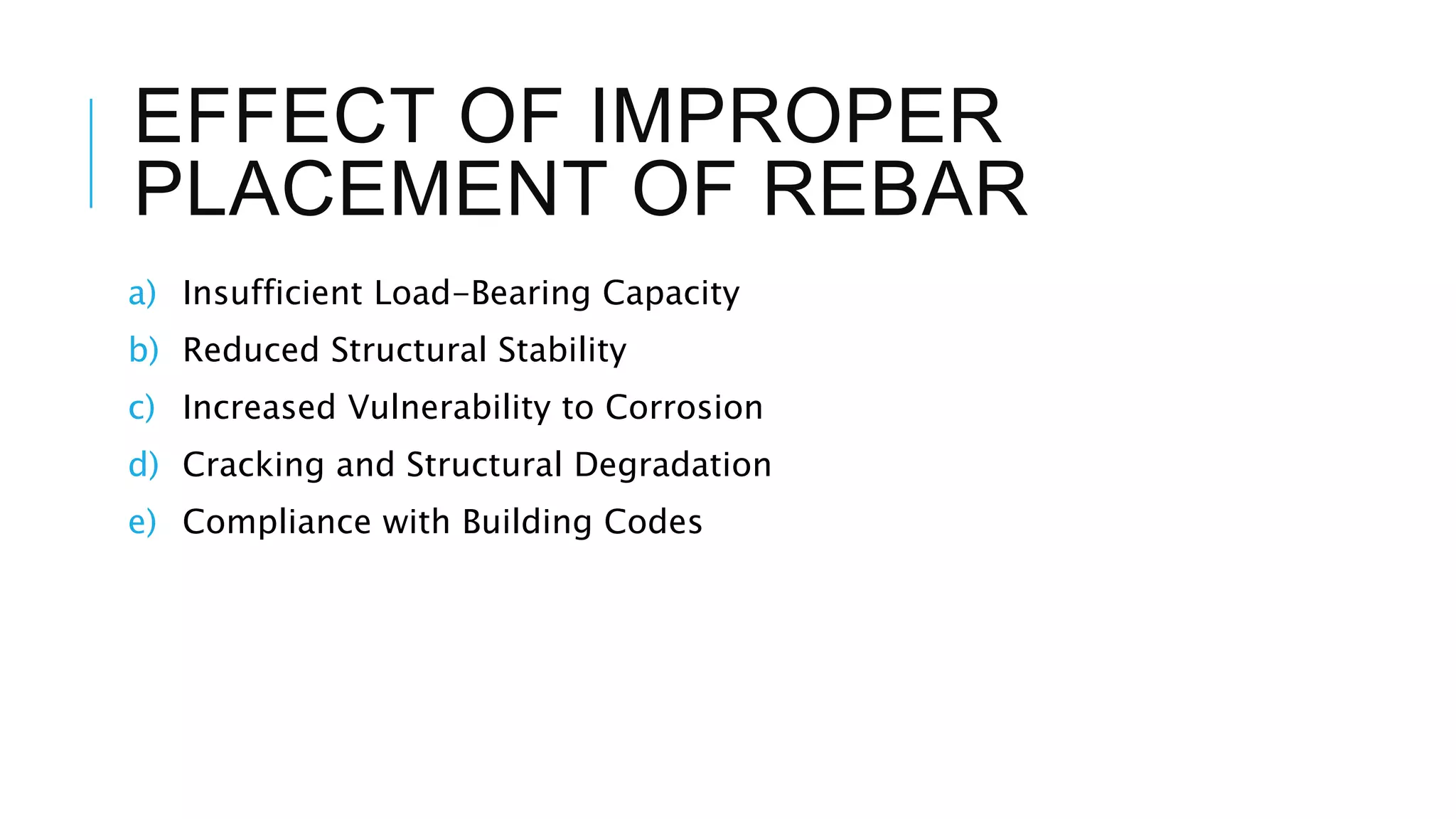
- Improper placement can result in insufficient load capacity, reduced stability, and vulnerability to corrosion.
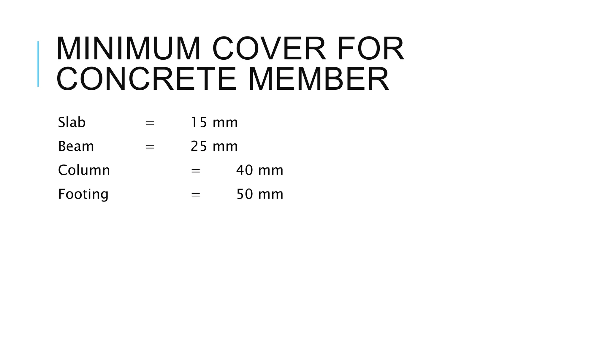
- Placement should follow established standards and guidelines to comply with building codes.
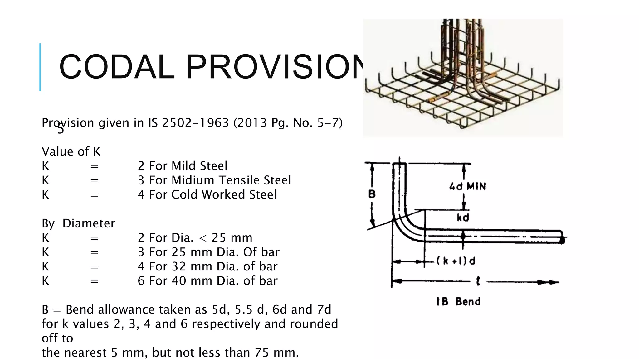
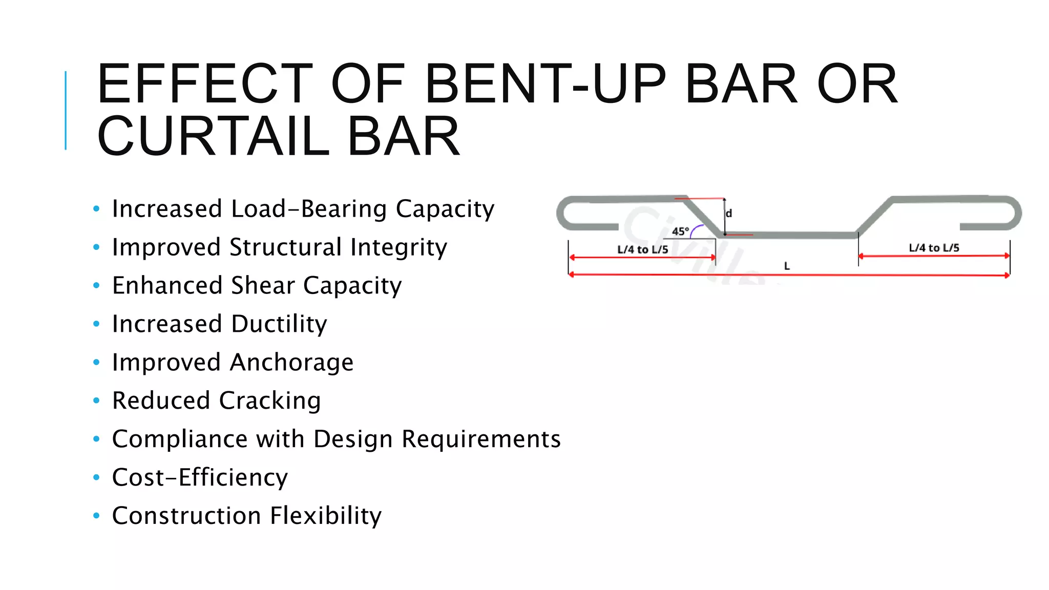
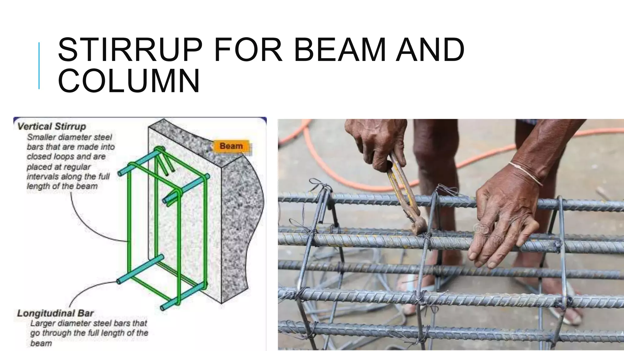
- Elements like hooks, bends, bent bars, and stirrups are discussed in terms of their effects and code provisions.