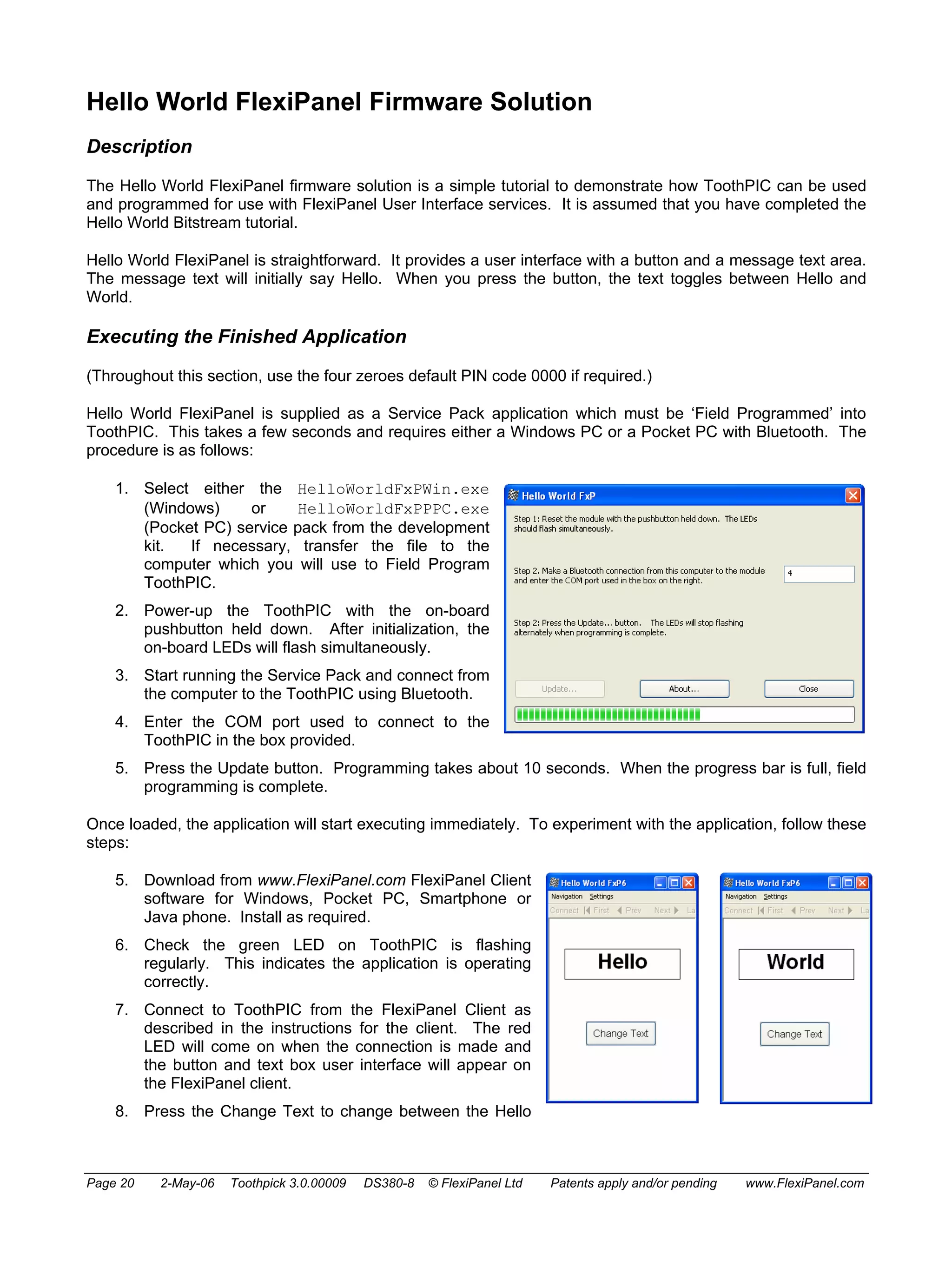
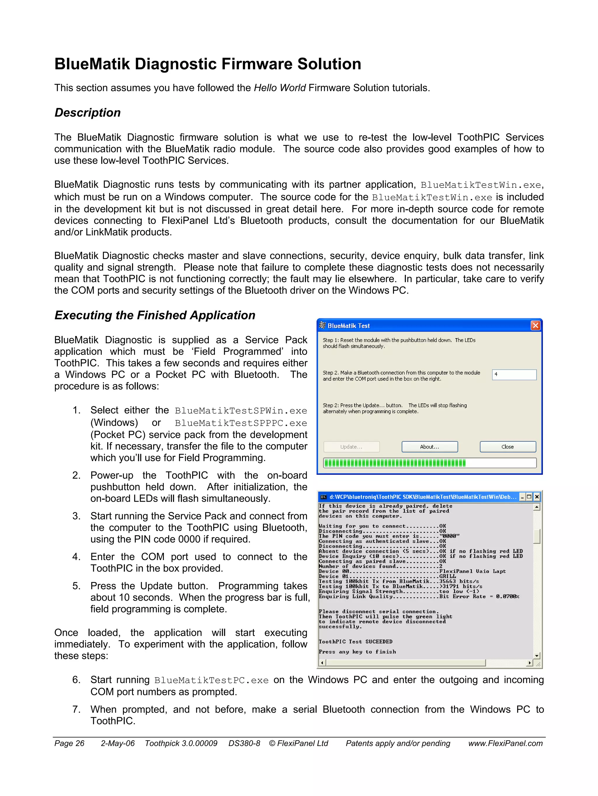
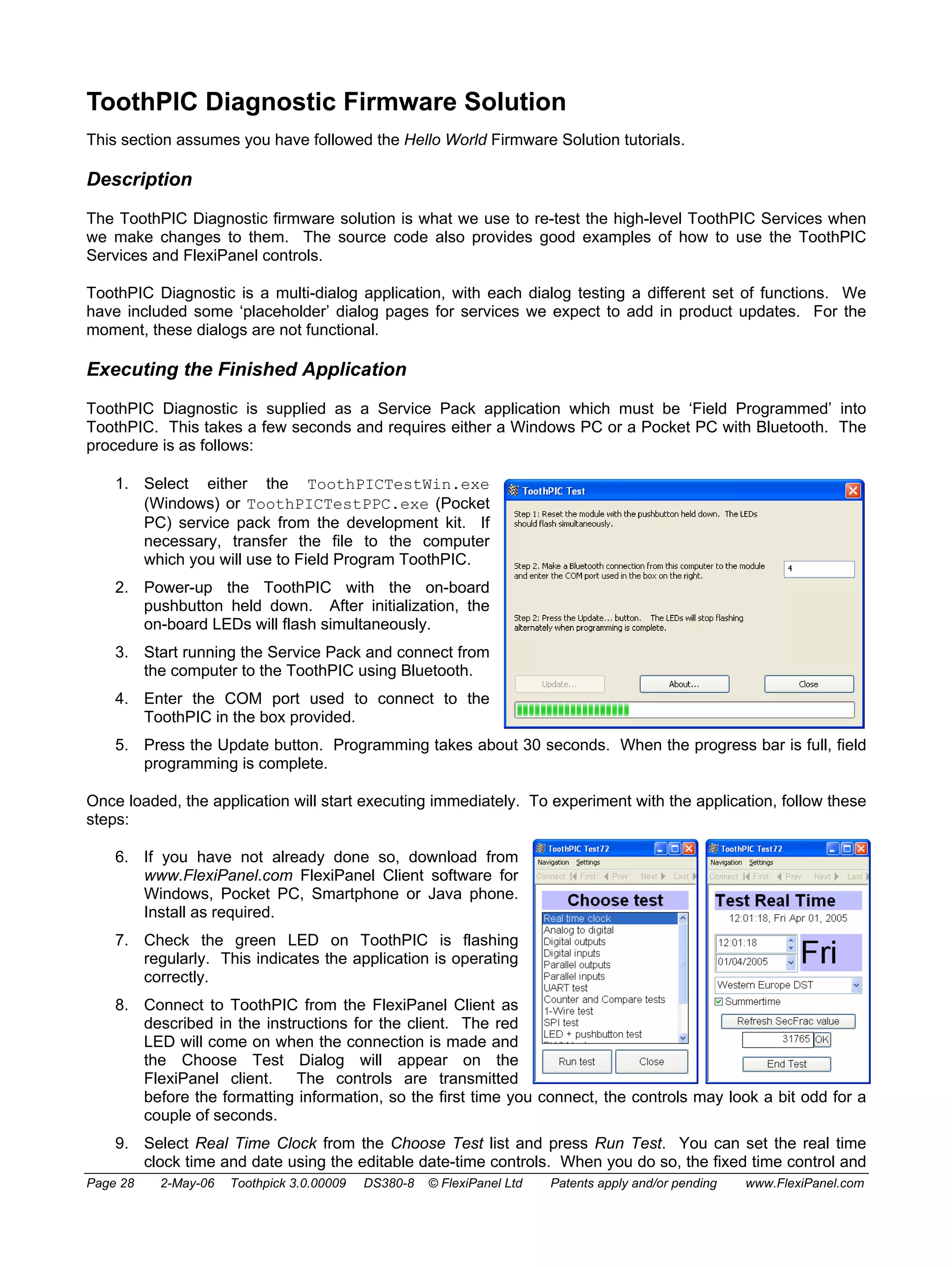
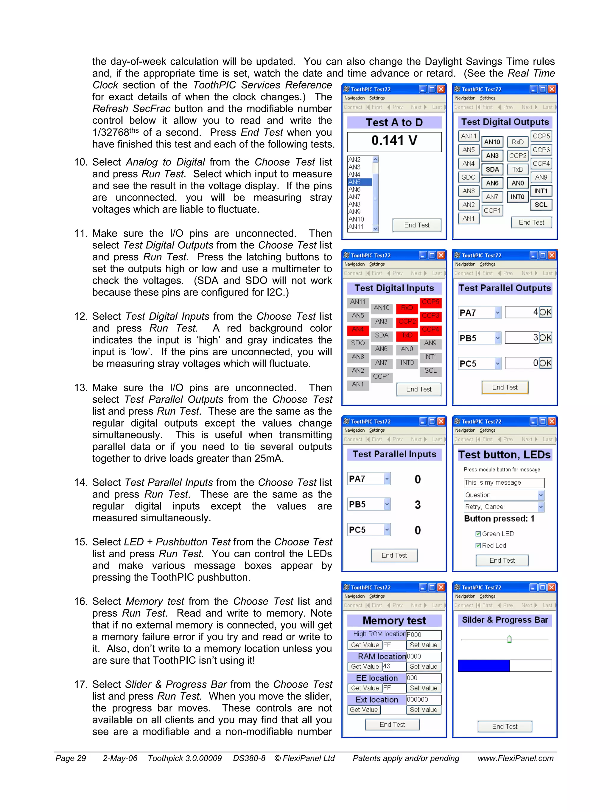
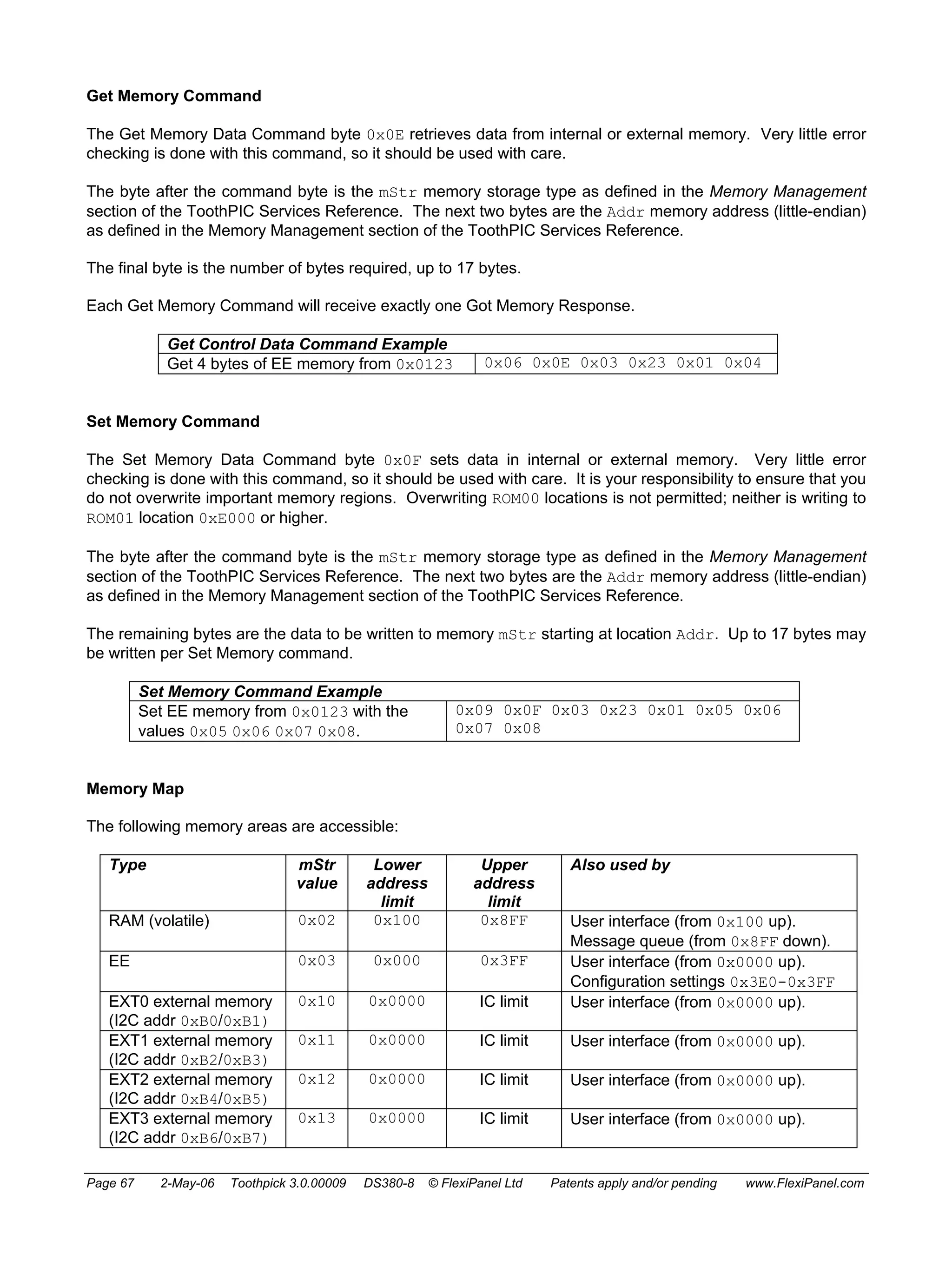
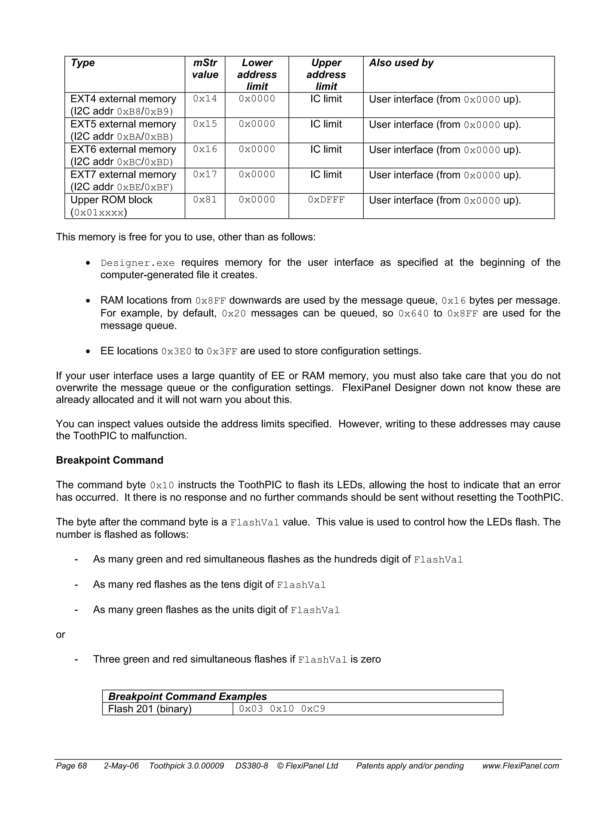
Downloaded 20 times

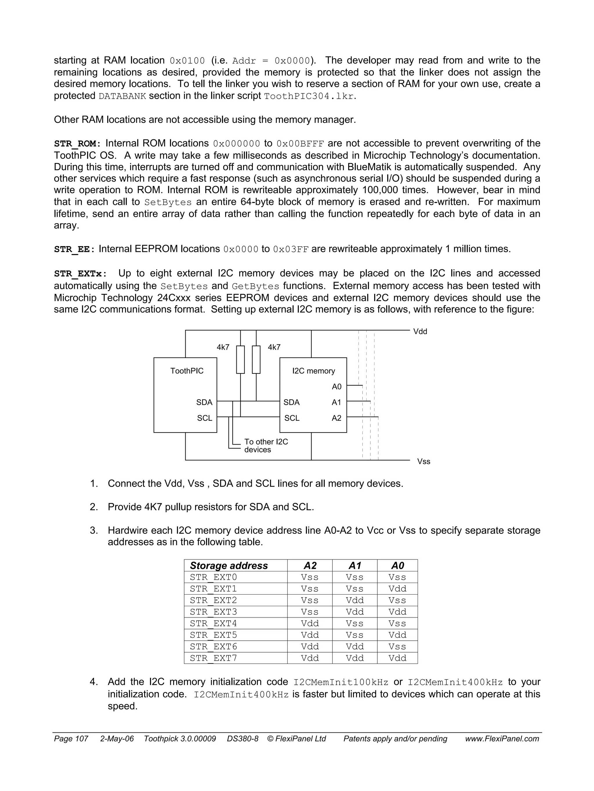
![3. Open the file ToothPIC303.c in development kit main directory and save it in your project directory.
This file allows you to customize the ToothPIC Services for this specific application. In this case the
only modification required is to change the device name. Replace the line:
rom unsigned char pLocalName[LOCALNAMELEN] = "ToothPIC 3.0";
with the line:
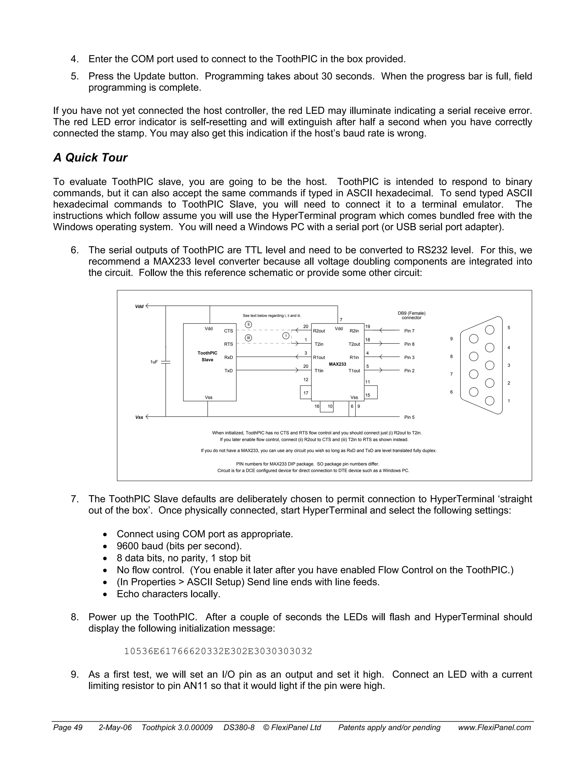
rom unsigned char pLocalName[LOCALNAMELEN] = "Hello World Bit";
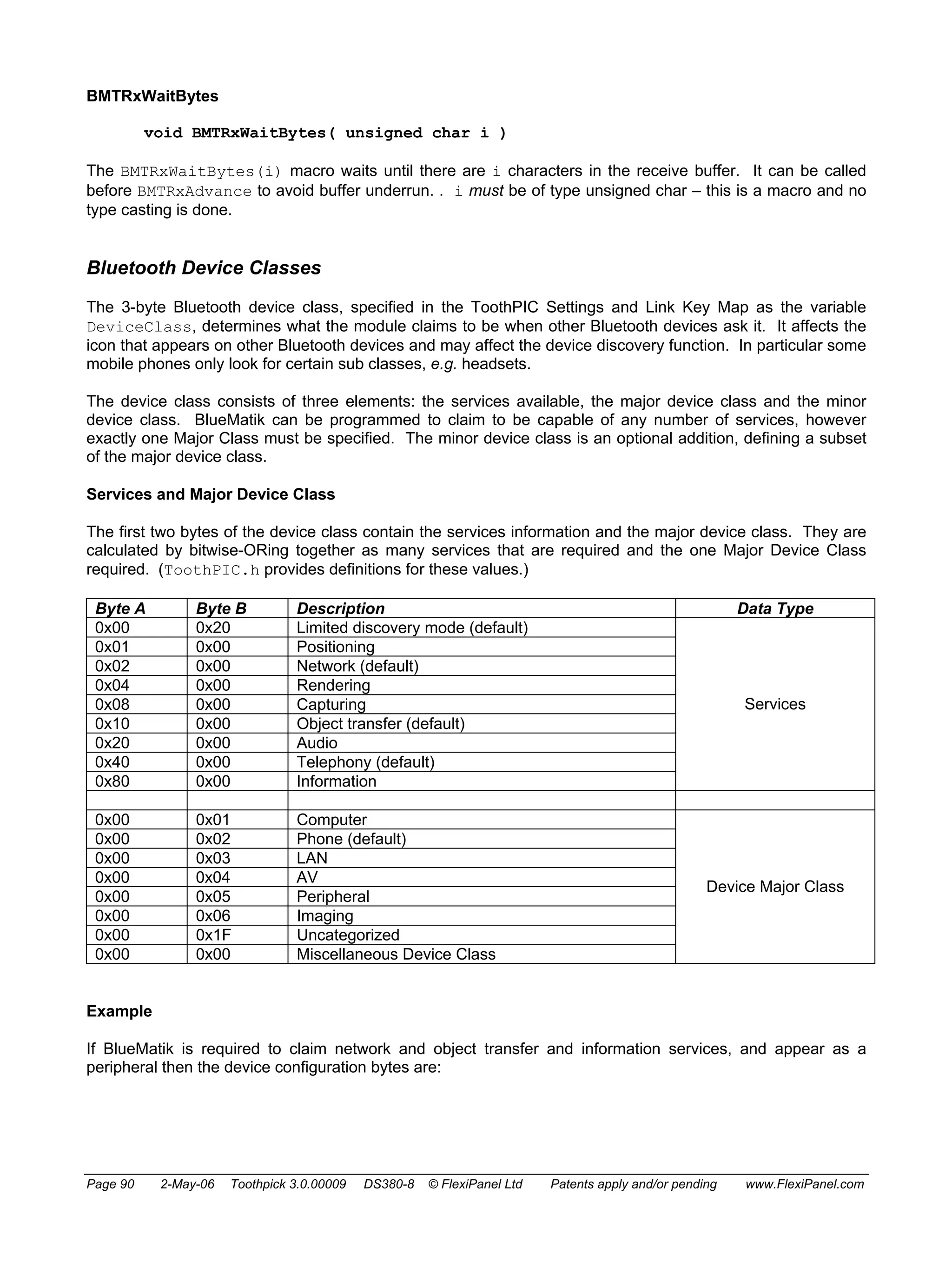
Note the many other settings in the file: PIN codes, device classes, etc. You can modify the values
but it is very important that you do not modify the order or the size of these variable declarations. This
is because during Wireless Field Programming, your application code gets updated but the ToothPIC
Services do not.
4. Open the file Main.c which is in the development kit main directory and save it in your project
directory with the name HelloWorldBit.c. This file is an ‘empty shell’ main application containing
all the functions you need to provide code for in your application. The ‘empty shell’ simply flashes
LEDs to indicate whether or not it is functioning correctly. Note how it contains a main function which
initializes and then runs in an infinite loop. The functions HighInterrupt, LowInterrupt,
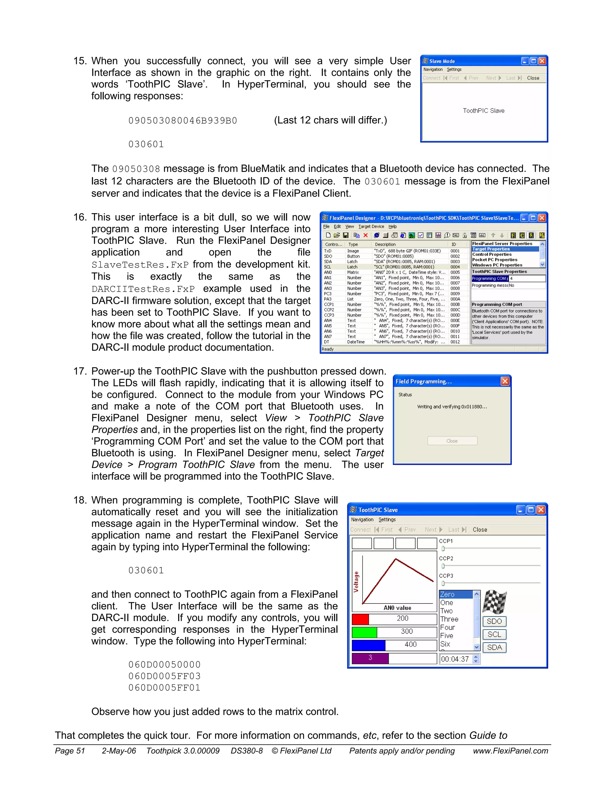
ErrorStatus, BMTEvent and FxPEvent are ‘callbacks’ which are called by ToothPIC services
when certain events occur. For example, the LowInterrupt is called once per second with the
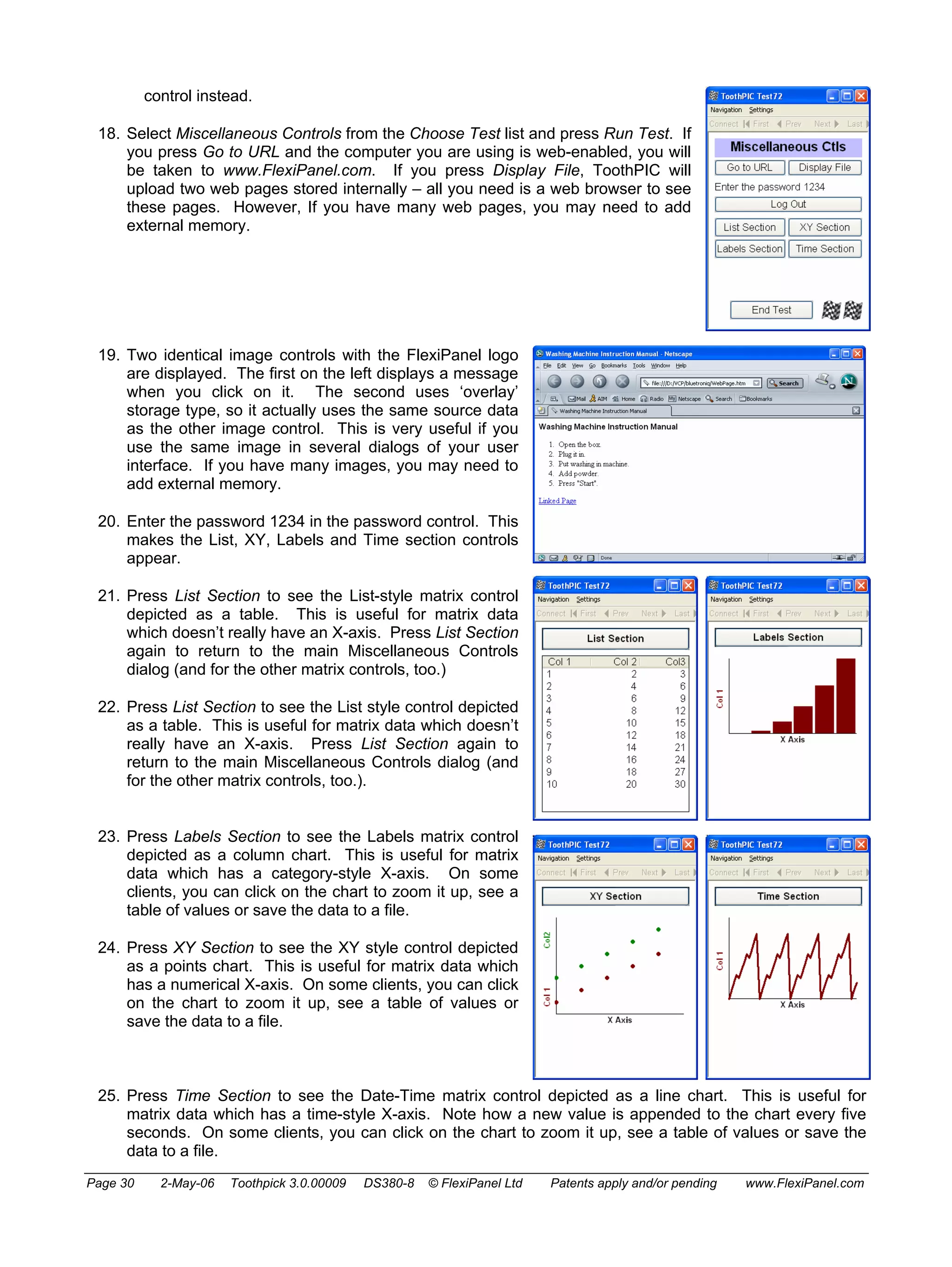
interrupt flag SWI_Tick set. Main.c clears the flag – if it did not, ToothPIC would keep calling
LowInterrupt because it would assume that the interrupt had not yet been serviced.
5. The first change to be made to HelloWorldBit.c is to tell the BlueMatik radio to enter slave mode
so other devices can connect to it. Since this will also be necessary after each disconnection, the
static variable InSlaveMode will keep track of whether the slave mode command needs to be send.
Place the following line at the beginning of the file before the main declaration:
Bool InSlaveMode = False; // false if we need to send a BMTC_Slave command
and insert the following code inside the infinite loop of the main function:
if (!InSlaveMode)
{
BMTCommand( BMTC_Slave, 0, 0 ); // Start BlueMatik binary service
AwaitBMTOK;
InSlaveMode = True;
}
This will put the radio in slave mode whenever the flag InSlaveMode is not set.
6. If a remote device connects to ToothPIC and then disconnects, ToothPIC will no longer be in slave
mode, so it needs to be put back into slave mode again. To do this, a BMTE_Disco message is sent
to the BMTEvent callback when the remote device disconnects. At the same time, we will trap the
BMTE_Connect message and light the red LED when a remote device is connected. Add the
following code to the BMTEvent callback function:
if ( EventID==BMTE_Connect )
{
// turn on red led during connection
LedRed = LedRedOn;
}
if ( EventID==BMTE_Disco )
{
// turn off red led after disconnection
LedRed = LedRedOff;
// re-enter slave mode
Page 18 2-May-06 Toothpick 3.0.00009 DS380-8 © FlexiPanel Ltd Patents apply and/or pending www.FlexiPanel.com](https://image.slidesharecdn.com/picbluetooth-141029141751-conversion-gate02/75/Pic-bluetooth-18-2048.jpg)

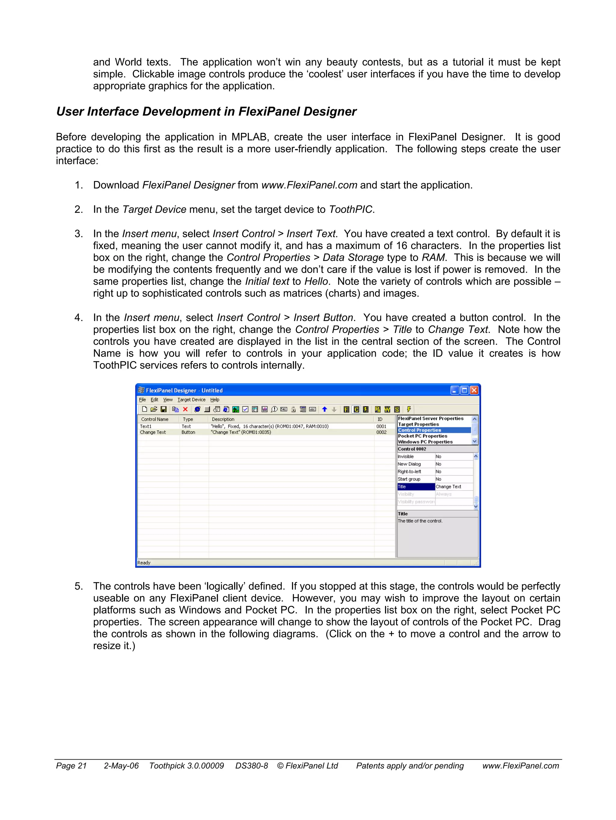
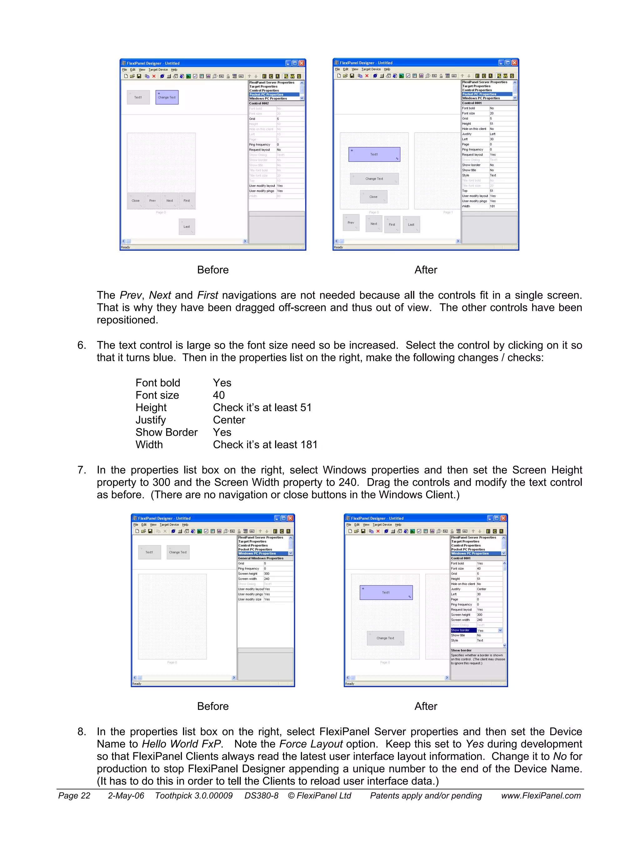

![memory. The header file contains computer-generated macros to make it easier to access the
controls from your application code.
4. Open the file ToothPIC303.c in the development kit main directory and save it in your project
directory. This file allows you to customize the ToothPIC Services for this specific application. In this
case the only modification required is to change the device name. At the beginning of the file,
#include the file HelloWorldRes.h created by FlexiPanel Designer. The code will then begin as
follows:
#define __ToothPIC_c__
#include "ToothPIC.h"
#include <p18f6720.h>
// If programming a FlexiPanel UI from FlexiPanel Designer using data files,
// include the header file Designer creates, (comment out otherwise)
#include "HelloWorldRes.h"
5. Open the file Main.c development kit main directory and save it in your project directory with the
name HelloWorldFxP.c. This file is an ‘empty shell’ main application containing all the functions
you need to provide code for in your application. At the beginning of the file, #include the file
HelloWorldRes.h created by FlexiPanel Designer. Also create static text variables for the words
“Hello and World, so that the code begins as follows:
#include "ToothPIC.h"
#include <p18f6720.h>
#include "HelloWorldRes.h"
rom unsigned char * szHello = "Hellorn";
rom unsigned char * szWorld = "Worldrn";
6. During initialization, the FlexiPanel User Interface server must be started. Unlike regular BlueMatik
slave mode, this does not need to be re-started each time a device disconnects so the code is simpler.
Place the following lines immediately prior to the start of the infinite look in the main function:
FxPCommand( FxPC_Start, 0, 0 ); // Start FlexiPanel service
AwaitBMTOK; // Service operating, no client
7. Events that happen to the FlexiPanel server are reported in the FxPEvent callback. Add the
following lines to the callback function so that the red LED comes on when a verified client connects:
if ( EventID==FxPE_Connect )
{
// turn off red led during connection
LedRed = LedRedOn;
}
if ( EventID==FxPE_Disco )
{
// turn off red led after disconnection
LedRed = LedRedOff;
}
8. Finally, code must be added to process the event when the ChangeText button is pressed. Add the
following lines to the callback function:
// Check for control events
if ( EventID==FxPE_ClntUpdate )
{
// If the button was pressed...
if (*((unsigned short*) pData) == ID_Change_Text_2)
{
// Is the current text value Hello or World?
if (pText1_1[0] == 'H')
{
// set the text value to World and update the client
Page 24 2-May-06 Toothpick 3.0.00009 DS380-8 © FlexiPanel Ltd Patents apply and/or pending www.FlexiPanel.com](https://image.slidesharecdn.com/picbluetooth-141029141751-conversion-gate02/75/Pic-bluetooth-24-2048.jpg)


![3. To customize the I/O configuration, you will need to modify the I/O configuration data structure
initialized in DARCIIConfig.c and described in detail in DARCIIConfig.h. Rather than modify the
DARCIIConfig.c file directly, it is better to overwrite the data during program initialization. This
allows you to use the macros in DARCIITestRes.h so that if you add or delete controls, the control
ID information is automatically updated. (The SetBytes function only writes to Flash memory if the
values are different from the desired values, so this will not exhaust the Flash memory.) To customize
the I/O configuration, open the file DARC-II.c and insert the following lines at the beginning of the
main() function (or copy them from the file DARC-II Customized.c file in the development kit):
// main program
#include "DARCIITestRes.h"
rom unsigned char szMyName[] = "My Product Title";
void main( void )
{
unsigned char cVal;
PulseClearCountDown = 0;
RefeshInputsNow = 0;
// if no BlueMatik, flash red led rapidly
while ((ToothPICSemaphores&TPSF_BMTEXISTS)==0)
{
LedRed = ~LedRed;
msDelay(50);
}
// customize DARCcfg
cVal = 0x55; // indicates config data has been initialized
SetBytes( STR_ROM00, (ADD)&DARCcfg.Initialized, 0, &cVal, 1 );
// device name
SetBytes( STR_ROM00, (ADD)DARCcfg.ServerName, szMyName, 0, MAXNAMELENGTHINCZ );
// four analog channels, AN0 to AN3
cVal = 0x04;
SetBytes( STR_ROM00, (ADD)&DARCcfg.nAnalogChannel, 0, &cVal, 1 );
// configure I/O; note default values are zeroes so if a value is zero,
/ we don't bother altering it
// DARCcfg.h explains the cVal values being used
cVal = 0x01; // output
SetBytes( STR_ROM00, (ADD)&DARCcfg.PinFuncAN9, 0, &cVal, 1 );
SetBytes( STR_ROM00, (ADD)&DARCcfg.PinFuncAN10, 0, &cVal, 1 );
SetBytes( STR_ROM00, (ADD)&DARCcfg.PinFuncAN11, 0, &cVal, 1 );
SetBytes( STR_ROM00, (ADD)&DARCcfg.PinFuncTxD, 0, &cVal, 1 );
SetBytes( STR_ROM00, (ADD)&DARCcfg.PinFuncSCL, 0, &cVal, 1 );
SetBytes( STR_ROM00, (ADD)&DARCcfg.PinFuncSDA, 0, &cVal, 1 );
SetBytes( STR_ROM00, (ADD)&DARCcfg.PinFuncSDO, 0, &cVal, 1 );
cVal = 0x02; // PWM output
SetBytes( STR_ROM00, (ADD)&DARCcfg.PinFuncCCP1, 0, &cVal, 1 );
SetBytes( STR_ROM00, (ADD)&DARCcfg.PinFuncCCP2, 0, &cVal, 1 );
SetBytes( STR_ROM00, (ADD)&DARCcfg.PinFuncCCP3, 0, &cVal, 1 );
cVal = 0x03; // Parallel A and Parallal C are both 3-bits wide
SetBytes( STR_ROM00, (ADD)&DARCcfg.ParallelA, 0, &cVal, 1 );
SetBytes( STR_ROM00, (ADD)&DARCcfg.ParallelC, 0, &cVal, 1 );
cVal = 0x02; // Timebase is 3.2us (
SetBytes( STR_ROM00, (ADD)&DARCcfg.ParallelA, 0, &cVal, 1 );
cVal = 0xFF; // PWM period is (0xFF + 1) = 256 Timebase units
SetBytes( STR_ROM00, (ADD)&DARCcfg.PWMPeriod, 0, &cVal, 1 );
cVal = 0x05; // Refresh every two seconds
SetBytes( STR_ROM00, (ADD)&DARCcfg.RefreshRate, 0, &cVal, 1 );
// link controls to I/O
cVal = TFP_BILT_TxD;
SetBytes( STR_ROM00, (ADD)&DARCcfg.ToFromPin[ID_TxD_1B], 0, &cVal, 1 );
cVal = TFP_BILT_SDO;
SetBytes( STR_ROM00, (ADD)&DARCcfg.ToFromPin[ID_SDO_7], 0, &cVal, 1 );
cVal = TFP_BILT_SDA;
SetBytes( STR_ROM00, (ADD)&DARCcfg.ToFromPin[ID_SDA_8], 0, &cVal, 1 );
cVal = TFP_BILT_SCL;
SetBytes( STR_ROM00, (ADD)&DARCcfg.ToFromPin[ID_SCL_9], 0, &cVal, 1 );
cVal = TFP_NDTM_AN0;
SetBytes( STR_ROM00, (ADD)&DARCcfg.ToFromPin[ID_AN0_18], 0, &cVal, 1 );
cVal = TFP_NDTM_AN1;
SetBytes( STR_ROM00, (ADD)&DARCcfg.ToFromPin[ID_AN1_C], 0, &cVal, 1 );
cVal = TFP_NDTM_AN2;
SetBytes( STR_ROM00, (ADD)&DARCcfg.ToFromPin[ID_AN2_D], 0, &cVal, 1 );
cVal = TFP_NDTM_AN3;
SetBytes( STR_ROM00, (ADD)&DARCcfg.ToFromPin[ID_AN3_E], 0, &cVal, 1 );
cVal = TFP_NDTM_ParallelC;
Page 39 2-May-06 Toothpick 3.0.00009 DS380-8 © FlexiPanel Ltd Patents apply and/or pending www.FlexiPanel.com](https://image.slidesharecdn.com/picbluetooth-141029141751-conversion-gate02/75/Pic-bluetooth-39-2048.jpg)
![SetBytes( STR_ROM00, (ADD)&DARCcfg.ToFromPin[ID_PC3_F], 0, &cVal, 1 );
cVal = TFP_L_ParallelA;
SetBytes( STR_ROM00, (ADD)&DARCcfg.ToFromPin[ID_PC3_F], 0, &cVal, 1 );
cVal = ID_CCP1_11;
SetBytes( STR_ROM00, (ADD)&DARCcfg.ToFromPin[TFP_NDTM_CCP1], 0, &cVal, 1 );
cVal = ID_CCP2_12;
SetBytes( STR_ROM00, (ADD)&DARCcfg.ToFromPin[TFP_NDTM_CCP2], 0, &cVal, 1 );
cVal = ID_CCP3_13;
SetBytes( STR_ROM00, (ADD)&DARCcfg.ToFromPin[TFP_NDTM_CCP3], 0, &cVal, 1 );
cVal = TFP_BILT_AN4;
SetBytes( STR_ROM00, (ADD)&DARCcfg.ToFromPin[ID_AN4_14], 0, &cVal, 1 );
cVal = TFP_BILT_AN5;
SetBytes( STR_ROM00, (ADD)&DARCcfg.ToFromPin[ID_AN5_15], 0, &cVal, 1 );
cVal = TFP_BILT_AN6;
SetBytes( STR_ROM00, (ADD)&DARCcfg.ToFromPin[ID_AN6_16], 0, &cVal, 1 );
cVal = TFP_BILT_AN7;
SetBytes( STR_ROM00, (ADD)&DARCcfg.ToFromPin[ID_AN7_17], 0, &cVal, 1 );
// if darc data has been programmed, set name and pin code
// new name only appears in device discovery after ToothPIC reset
if (DARCcfg.Initialized==0x55)
{
SetBytes( STR_ROM00, (ADD)pLocalName, DARCcfg.ServerName, 0,MAXNAMELENGTHINCZ);
SetBytes( STR_ROM00, (ADD)pszPIN, DARCcfg.PINCode, 0, MAXPINLENGTHINCZ );
}
4. Compile the code and program it into the ToothPIC.
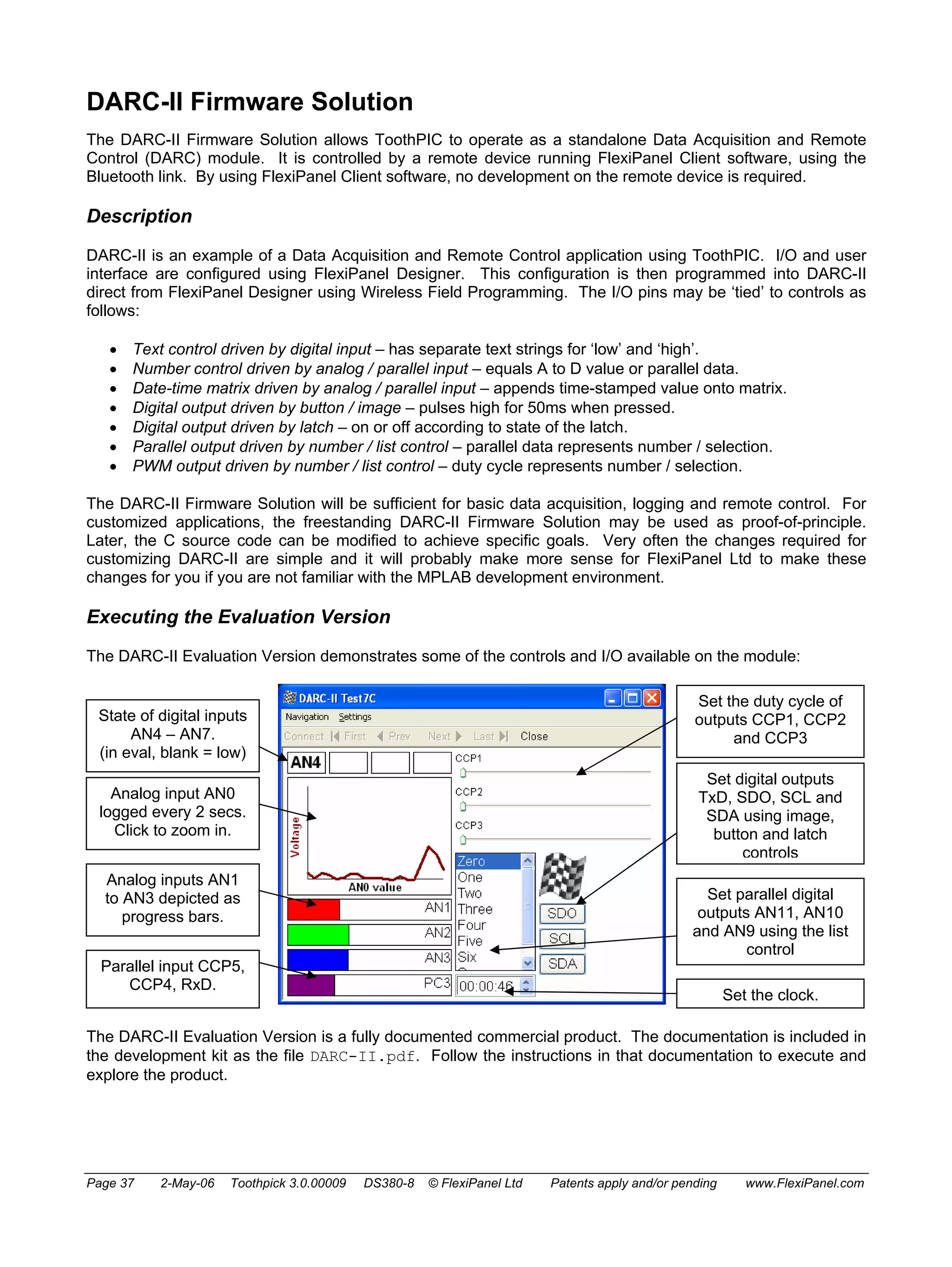
The version of DARC-II that you have created should perform in exactly the same way as the example in the
Evaluation Version, except that now you can modify the rest of the code as you wish. The key features of the
source code are described below.
Initialization
After variables are initialized, the I/O and Bluetooth security are set as specified by the DARCcfg data
structure. The FlexiPanel user interface server is started. Finally, the function RefreshInputs() is called
to correctly set the state of any controls which are driven by the state of the I/O pins.
Main Program Loop
In the main program loop, the software determines whether the semaphore PulseClearCountDown has
been raised to request that it clears, after a 50ms pause, any I/O pins which are configured for pulse output. If
the semaphore is raised at any time while it is counting up to 50ms, is starts its 50ms delay count again. This
ensures that if two pins are pulsed in rapid succession, both pulses will be at least 50ms long. If the
semaphore was not raised at all, DARC-II simply waits 50ms. Either way, the delay is probably 50ms,
possibly a bit more.
If the refresh rate is 100ms, 200ms or 500ms, DARC-II waits the specified time (less the 50ms already waited)
and calls RefreshInputs()to update the inputs. If the refresh rate is longer than this, the LowInterrupt
callback will raise the semaphore RefeshInputsNow if it is time to refresh the inputs. In this case, DARC-II
inspects the semaphore to decide whether to call RefreshInputs().
High Interrupt
No high priority interrupts are expected nor provided for.
Low Interrupt
One type of low priority interrupts is provided for: when the clock ticks.
Every second, a SWI_Tick software interrupt will be received. DARC-II inverts the green LED to show that is
it working correctly. Note that this is not infallible indication since, if the main program loop hangs, SWI_Tick
software interrupts will probably still be generated correctly.
Next DARC-II decides whether it is time to raise the RefeshInputsNow semaphore and does so if required.
Page 40 2-May-06 Toothpick 3.0.00009 DS380-8 © FlexiPanel Ltd Patents apply and/or pending www.FlexiPanel.com](https://image.slidesharecdn.com/picbluetooth-141029141751-conversion-gate02/75/Pic-bluetooth-40-2048.jpg)


![ToothPIC Slave Development.
Migration to MPLAB
The ToothPIC Slave Firmware Solution can do most things that ToothPIC is capable of. You may, however,
wish to customize it either to migrate your host controller application inside ToothPIC or to access specialized
PIC functions.
To make customization possible, we have made the C source code freely available for you to customize. To
do this you will need to know how to program microcontrollers in C and also be familiar with Microchip
Technology’s MPLAB development environment.
Since many customization requirements are relatively simple, we offer a paid-for customization service to
commercial developers who are not familiar with programming in the MPLAB development environment.
Please contact us for details.
The following instructions allow you to migrate the Evaluation Application solution to the MPLAB development
environment. If you have not already done so, please study the Hello World applications to understand how
interaction with ToothPIC Services works. The relevant code is in the file Slave.c in the Development Kit.
User Interface
If you customize the application, it is easiest to program the user interface by setting ToothPIC MPLAB as the
Designer target and including the files generated by FlexiPanel Designer in the project in place of
SlaveDefaultRes.c and SlaveDefaultRes.h. The header file will contain useful macros which get
updated if control IDs change.
Because the ToothPIC Slave Firmware Solution does not know the User Interface information in advance, the
required memory needed to be reserved for it. Therefore you may remove the lines:
#pragma romdata Section_010000 = 0x0101D7
rom unsigned char p010000[0x3E29]; // first 0x01D7 Bytes in SlaveDefaultRes.h
#pragma romdata Section_014000 = 0x014000
rom unsigned char p014000[0x4000];
#pragma romdata Section_018000 = 0x018000
rom unsigned char p018000[0x4000];
#pragma romdata Section_01C000 = 0x01C000
rom unsigned char p01C000[0x3000];
#pragma romdata
and also the lines:
#pragma udata TP_UIRAM000 // located at 0x100 - 0x1FF
unsigned char pFxPRAM000B[0xFF];
#pragma udata TP_UIRAM100 // located at 0x200 - 0x1FF
unsigned char pFxPRAM100[0x100];
#pragma udata TP_UIRAM200 // located at 0x300 - 0x1FF
unsigned char pFxPRAM200[0x100];
#pragma udata TP_UIRAM300 // located at 0x400 - 0x8FF
unsigned char pFxPRAM300[0x100];
#pragma udata TP_UIRAM400 // located at 0x500 - 0x8FF
unsigned char pFxPRAM400[0x100];
#pragma udata TP_UIRAM500 // located at 0x600 - 0x8FF
unsigned char pFxPRAM500[0x100];
#pragma udata TP_UIRAM600 // located at 0x700 - 0x8FF
unsigned char pFxPRAM600[0x100];
#pragma udata TP_UIRAM700 // located at 0x800 - 0x8FF
unsigned char pFxPRAM700[0x100];
#pragma udata
However, you must reserve space for your message queue just below 0x900, otherwise the linker might try to
use the memory. The following example allocates enough memory for a message queue of 11 messages of
22 bytes:
#pragma udata MESSAGESTACK=0x80E // located at 0x80E - 0x8FF
unsigned char pMessage[0xF2];
#pragma udata
Page 52 2-May-06 Toothpick 3.0.00009 DS380-8 © FlexiPanel Ltd Patents apply and/or pending www.FlexiPanel.com](https://image.slidesharecdn.com/picbluetooth-141029141751-conversion-gate02/75/Pic-bluetooth-52-2048.jpg)

![Guide to ToothPIC Slave Development
HyperTerminal Setup
The easiest way to experiment with ToothPIC Slave is to connect it to a terminal emulator such as
HyperTerminal, which is bundled with the Windows operating systems. Notes on how to do this are given in
the section ToothPIC Slave Firmware Solution.
Note: When sending ASCII commands to ToothPIC, if you make a typing error, avoid pressing delete, or
pressing enter repeatedly until an error message is generated. This is because the delete and carriage return
characters are legitimate binary characters. Instead, keep tapping a completely illegal character (e.g. ‘z’) until
the error message 0302F1 is generated. Then you can start typing a new command.
BASIC Stamp Host Setup
ToothPIC can be connected directly to BASIC Stamp using any data pins. To send data at 9600 baud to
ToothPIC, use the following BASIC command (substitute RxDpin, RTSpin with the actual pins used):
SEROUT RxDpinRTSpin, 240, [Command]
To receive data at 9600 baud from ToothPIC, use the following BASIC command (substitute TxDpin, CTSpin
with the actual pins used):
SERIN TxDpinCTSpin, 240, [Response buffer]
The BASIC Stamp doesn’t buffer data so you will need to call SERIN regularly to avoid the ToothPIC Slave’s
message queue from overflowing. You can use the INT1 is DATA configuration command to set INT1 as an
output which is high whenever messages are in the queue waiting to be processed, and low otherwise.
PIC Host Microcontroller Setup
Another UART-equipped PIC can be connected directly to the ToothPIC Slave. Simply cross over the
connections (i.e. connect RxD to TxD, CTS to RTS, etc). The sample code provided for the ToothPIC Slave
firmware solution shows how to write interrupt-driven, buffered serial I/O and you can copy from it to develop
your application code.
External memory
External memory may be used as described in the Memory Management section of the ToothPIC services
reference. This memory may then be allocated to the FlexiPanel Server or accessed using the Get Data and
Set Data commands. Use the Config Slave (I2C Memory Setup) command to set up the SDA and SCL pins.
Adding a FlexiPanel User Interface
FlexiPanel User Interfaces can be written to ToothPIC Slave at any time using FlexiPanel Designer as shown
in the Quick Tour section of the ToothPIC Slave Firmware Solution. The RAM space is limited to 0x800 bytes
less the number of bytes required for the message queue (22 bytes per message). The Flash ROM space is
limited to 0xE000 bytes.
Beware that control ID value may change if you insert a dialog or a control earlier in FlexiPanel Designer’s
control list. You may therefore wish to define constants in your host controller code to simplify changes to ID
values. It is also good practice to complete a user interface design as much as possible before coding. This
is not for the sake of easier coding; it is because the result is more intuitive to the user.
Page 55 2-May-06 Toothpick 3.0.00009 DS380-8 © FlexiPanel Ltd Patents apply and/or pending www.FlexiPanel.com](https://image.slidesharecdn.com/picbluetooth-141029141751-conversion-gate02/75/Pic-bluetooth-55-2048.jpg)


![unsigned char Channel = 1;
unsigned long ADResult;
SetADChan( Channel ); // select a to d channel
CyclesDelay16plus16times( 9 ); // 1.6us delay to charge S & H cap
StartAtoD; // start a to d conversion
AwaitAtoDComplete; // await end of conversion
GetADResult10bit( ADResult ); // get result
ADResult = (ADResult*5000)/1024; // convert to millivolts
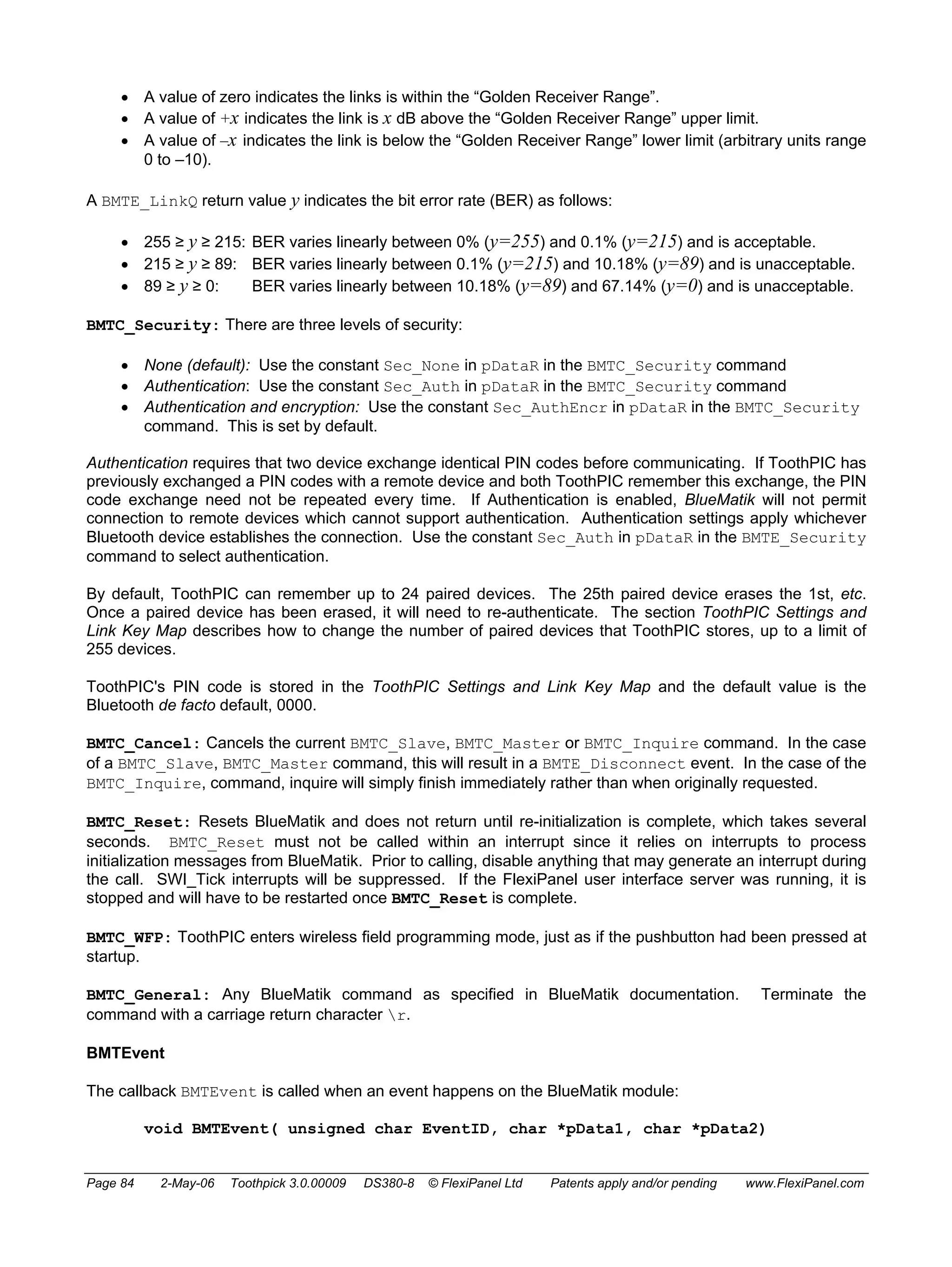
BlueMatik Control
BlueMatik Management
BlueMatik is connected to USART1 on the PIC18LF6720. The following definitions can be used to control
BlueMatik directly.
BMTSleep Turns BlueMatik off. In addition call ClearSemaphores to reset the
state of the ToothPIC services with respect to BlueMatik
BMTWake Turns BlueMatik on. In addition call ClearSemaphores to reset the
state of the ToothPIC services with respect to BlueMatik
AwaitBMTOK pauses until the previous BlueMatik command is complete
AwaitBMTConnect(TO) pauses until BlueMatik connection is complete or TO units of 100ms have
passed, triggering abandonment of connection
ConnectSuccess True if BlueMatik connection successfully completed, False if
abandoned
Examples:
ClearSemaphores
BlueMatikSleep // Go to sleep
ClearSemaphores
BlueMatikWake // Wake up (Assumes ClearSemaphores)
BMTCommand
The service BMTCommand sends a command to the BlueMatik module:
void BMTCommand (unsigned char CommandID, void *pData, rom void *pDataR)
BMTCommand will return immediately the command has been sent. Any response from BlueMatik will be in the
form of a BMTEvent callback. The commands are:
CommandID (hex
Command description *pData (or *pDataR if pData is
value)
null pointer)
BMTC_Slave (01) Enter slave mode – module becomes
discoverable and accepts incoming serial
connections
ignored
BMTC_Master
(02)
Establish serial port service connection with
remote device
Remote device Bluetooth ID
(unsigned char[6])
BMTC_Disco (03) Disconnect current serial connection ignored
Page 81 2-May-06 Toothpick 3.0.00009 DS380-8 © FlexiPanel Ltd Patents apply and/or pending www.FlexiPanel.com](https://image.slidesharecdn.com/picbluetooth-141029141751-conversion-gate02/75/Pic-bluetooth-81-2048.jpg)
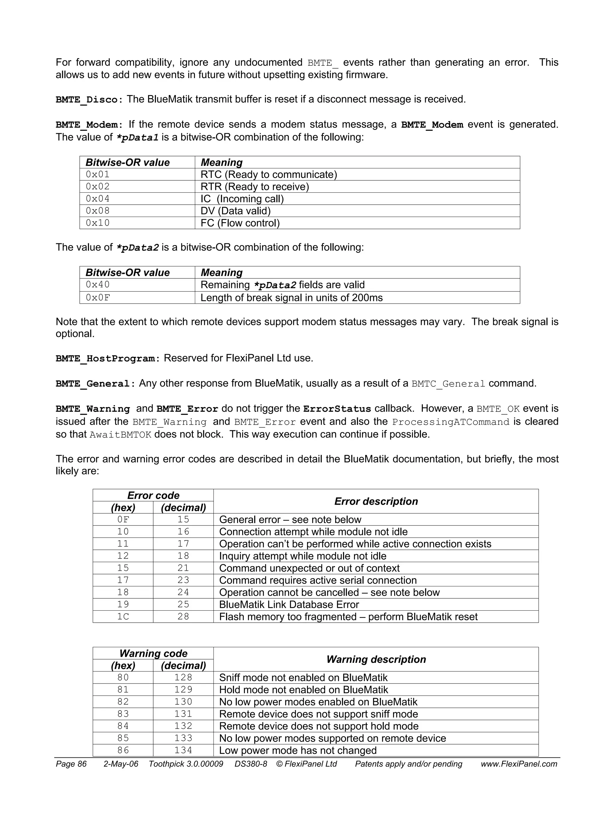
![CommandID (hex
value)
Command description *pData (or *pDataR if pData is
null pointer)
BMTC_Inquire
(04)
Search for other Bluetooth devices. Each
device found generates a BMTE_Found event.
Finally a BMTE_OK event generated.
inquiry duration in seconds as ASCII
hexadecimal (zero terminated
char[]), range 02 to 3C
BMTC_Security
(05)
Sets security level to none (Sec_None),
authentication (Sec_Auth) or authentication
and encryption (Sec_AuthEncr)
security level as ASCII digit (zero
terminated char[]) – see examples
below
BMTC_Hold (0A) Enter hold mode. ignored
BMTC_Sniff (08) Enter sniff mode. ignored
BMTC_SniffX
Exit sniff mode. ignored
(09)
BMTC_Signal
(07)
Enquire link signal strength. ignored
BMTC_LinkQ (06) Enquire link quality. ignored
BMTC_Cancel
(0B)
Cancel the current BMTC_Slave,
BMTC_Master or BMTC_Inquire command.
ignored
BMTC_Reset (0C) Reset BlueMatik. ignored
BMTC_WFP (0D) Enter Wireless Field Programming mode. ignored
BMTC_General
(FF)
Send arbitrary command to BlueMatik as
described in BlueMatik documentation.
ASCII command (zero terminated
char[])
Examples:
BMTCommand( BMTC_Slave, 0, 0 ); // Enter slave mode
AwaitBMTConnect( 0 ); // No timeout
unsigned char pBTAddr[] =
{ 0x01, 0x23, 0x45, 0x67, 0x89, 0xAB };
BMTCommand( BMTC_Master, (void *) pBTAddr, 0 ); // Connect to device
AwaitBMTConnect( 50 ); // 5 sec timeout
if (!ConnectSuccess) {...}; // Test connection timeout
BMTCommand( BMTC_Disco, 0, 0 ); // Disconnect
AwaitBMTOK;
BMTCommand( BMTC_Sniff, 0, 0 ); // Enter Sniff mode
AwaitBMTOK;
BMTCommand( BMTC_LinkQ, 0, 0 ); // Enquire link quality
AwaitBMTOK; // Creates BMTE_LinkQ event
// set device class to camera
rom static unsigned short long CamDevClass =
Dev_Imaging | ImDev_Display | ImDev_Camera | Svc_Capture;
BMTCommand( BMTC_DevClass, 0, &CamDevClass );
AwaitBMTOK;
BMTCommand( BMTC_Inquire, 0, (rom void *)"A" ); // 10 second inquiry
AwaitBMTOK;
BMTCommand( BMTC_Security, 0, Sec_AuthEncr ); // Authentication and
AwaitBMTOK; // encryption (default)
// Set hold parameters (max, min, hex units of 0.625ms)
BMTCommand( BMTC_General, 0, (rom void *)"AT+BSHP=200,80r" );
Page 82 2-May-06 Toothpick 3.0.00009 DS380-8 © FlexiPanel Ltd Patents apply and/or pending www.FlexiPanel.com](https://image.slidesharecdn.com/picbluetooth-141029141751-conversion-gate02/75/Pic-bluetooth-82-2048.jpg)
![AwaitBMTOK;
Notes:
BMTC_Inquire: Inquiry time is a tradeoff between speed and finding all devices. Searching for other
devices using the BMTC_Inquire command will not necessarily find all available devices if the inquiry time is
too short.
Bluetooth ID: The Bluetooth ID structure unsigned char[6] contains the non-significant address part
(2 bytes, MSB first), followed by the upper address part (1 byte), followed by the lower address part (3 bytes,
MSB first). Big-endian format (i.e. MSB first) is used in a departure from the C18 standard so that the array
linearly matches the 01:23:45:67:89:AB form of Bluetooth address notation.
BMTC_Slave: In slave mode, BlueMatik becomes discoverable and it waits for a remote device to connect to
it. When a master connects, a BMTE_Connect event occurs and the ToothPIC public data pRemoteBTAddr
will contain the Bluetooth address of the master. If the master disconnects, a BMTE_Disco event is
generated, the contents of pRemoteBTAddr will be cleared and BlueMatik the exits slave mode. To stay in
slave mode and await another connection from a remote device, it is necessary to re-enter slave mode. You
will need to use a semaphore to do this. See the Reset State
The following macros are defined to help you determine what caused the last reset. If none are true, the last
reset was a hardware reset applied to the NMCLR pin.
ResetOrWakeEventWasPowerOn
ResetOrWakeEventWasStackOverflow
ResetOrWakeEventWasStackUnderflow
ResetOrWakeEventWasSoftwareReset
ResetOrWakeEventWasInterrtuptOrNMCLRDuringSleep
ResetOrWakeEventWasWDTReset
ResetOrWakeEventWasWDTWakeup
ResetOrWakeEventWasBrownOut
Semaphores section for this exact example. Don’t send any data to BlueMatik until you get confirmation that
the connection was successful using AwaitBMTConnect and ConnectSuccess.
ToothPIC also uses the term ‘slave mode’ in a different sense, where theToothPIC module is controlled by a
host processor which via a conventional TTL serial connection. The firmware solution always referred to by its
full name, ‘ToothPIC Slave’.
BMTC_Master: In master mode, BlueMatik actively attempts to connect to the remote device specified by the
remote device ID. When connection is complete, a BMTE_Connect event occurs and the ToothPIC public
data pRemoteBTAddr will contain the Bluetooth address of the remote device. Then when master or slave
disconnects, a BMTE_Disco event is generated, the contents of pRemoteBTAddr will be cleared and
BlueMatik then exits master mode. Don’t send any data to BlueMatik until you get confirmation that the
connection was successful using AwaitBMTConnect and ConnectSuccess.
BMTC_Hold, BMTC_HoldX, BMTC_Sniff, BMTC_SniffX: The BlueMatik module supports two power
saving modes, Hold and Sniff, as described in the section Power Saving. They apply only when a connection
exists. To change from the default Hold and Sniff settings, consult the BlueMatik documentation and set the
required values using the BMTC_General command.
BMTC_Signal, BMTC_LinkQ: The BMTC_Signal and BMTC_LinkQ commands give an idea of the signal
strength and quality. The return values via the BMTE_Signal and BMTE_LinkQ BlueMatik events. The
BMTE_Signal return value indicates the signal strength as follows:
Page 83 2-May-06 Toothpick 3.0.00009 DS380-8 © FlexiPanel Ltd Patents apply and/or pending www.FlexiPanel.com](https://image.slidesharecdn.com/picbluetooth-141029141751-conversion-gate02/75/Pic-bluetooth-83-2048.jpg)
![EventID identifies the event that happens. pData1 and pData2 may contain related information depending
on the nature of the event:
EventID
Event description *pData1 *pData2
(hex value)
BMTE_OK (00) Command completed
OK
Not used Not used
BMTE_Error (01) Error message Error code (unsigned char) Not used
BMTE_Warning
(02)
BlueMatik warning
message
Warning code (unsigned
char)
Not used
BMTE_Connect
(03)
Connection established Remote device Bluetooth ID
(unsigned char[6])
Not used
BMTE_Disco (04) Connection terminated Not used Not used
BMTE_Found (05) Device found during
inquiry. One event per
device found.
Remote device’s Bluetooth ID
(unsigned char[6])
Remote device’s name
(zero terminated
char[])
BMTE_Paired (06) New remote device
successfully paired and
added to pair list
Remote device’s Bluetooth ID
(unsigned char[6])
Not used
BMTE_LinkQ (07) Link quality result Signal strength 0 to 255
(unsigned char)
Not used
BMTE_Signal (08) Signal strength result Signal strength –128 to 127
(char)
Not used
BMTE_LoPower
(09)
Low power mode
changed
Low power mode 0 to 2 (char) Low power mode
interval (int16)
BMTE_Modem (0A) Modem status message
from remote device
Modem status 0x00 to 0x1F
(unsigned char)
Break signal 0x00 to
0xFF
(unsigned char)
BMTE_HostProgram
(0B)
WFP host program
message received
Not used Not used
BMTE_General
(FF)
Other response, e.g.
from BMTE_General
command
Response text (zero terminated
char[])
Not used
Example:
void BMTEvent( unsigned char EventID, void *pData1, void *pData2 )
{
// error or warning
if ( EventID==BMTE_Error || ( EventID==BMTE_Error)
#ifdef RELEASE_VERSION
Reset(); // unanticipated error - reset
#else
Breakpoint( *((unsigned char*)pData1) ); // flash error number
#endif
// store link quality in uch
if ( EventID==BMTE_LinkQ ) uch = *(unsigned char *) pData1;
}
Notes:
BMTEvent may be called at any time, so care should be taken if modifying static values other than
semaphores which are also used by your main code.
Page 85 2-May-06 Toothpick 3.0.00009 DS380-8 © FlexiPanel Ltd Patents apply and/or pending www.FlexiPanel.com](https://image.slidesharecdn.com/picbluetooth-141029141751-conversion-gate02/75/Pic-bluetooth-85-2048.jpg)
![Error code 0x0F (general error), is generated when BlueMatik responds with an error message but specifies
no error number. If custom commands are being sent, it probably means that a command was not
understood. Error code 0x0F can also be generated (i) on disconnection if both sides attempt to initiate the
disconnection, or (ii) if data is sent before a connection was established or after it was closed (since BlueMatik
will try to interpret this data as a command). Note in particular that if a remote device disconnects while
ToothPIC is trying to send it data, a general error be generated. The correct response to this is to perform a
BMTC_Reset command to return BlueMatik to a known state. See any of the firmware solutions for an
example of how this is done.
BlueMatik Serial Communications
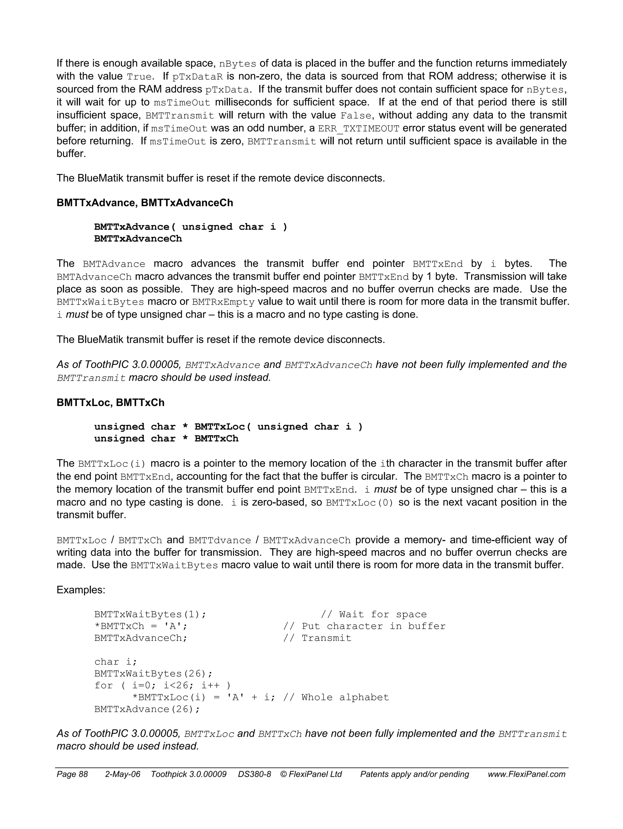
NOTE: As of ToothPIC 3.0.00005, the transmit buffer is not used and BMTTransmit will not return until the
data has been transmitted.
BlueMatik serial communications services allow you to send data to and receive data from Bluetooth devices
that BlueMatik is connected to. These services are not compatible with the FlexiPanel User Interface services
– you can use one or the other, but not both at the same time.
ToothPIC implements buffered I/O with fixed buffers of 256 bytes.
• RAM locations 0x800 to 0x8FF are reserved for the transmit buffer
• RAM locations 0x900 to 0x9FF are reserved for the receive buffer
ToothPIC employs the buffers as circular buffers and the following variables and macros are defined in
ToothPIC.h:
Definition Function
BMTRxStart Any data remaining in the buffer starts at pRxBuff[BMTRxStart].
BMTRxEnd Any data remaining in the buffer ends at pRxBuff[BMTRxEnd], having
wrapped around from the end to the beginning if necessary.
BMTRxNChar Number of characters in the receive buffer
BMTRxEmpty True if the receive buffer is empty
ResetBMTRx Resets state of receive buffer (all data will be lost)
BMTTxStart Any data remaining in the buffer starts at pTxBuff[BMTTxStart].
BMTTxEnd Any data remaining in the buffer ends at pTxBuff[BMTTxEnd], having
wrapped around from the end to the beginning if necessary.
BMTTxNChar Number of characters remaining in the transmit buffer
BMTTxSpace Number of spare bytes in the transmit buffer (max 255)
BMTTxEmpty True if the transmit buffer is empty
ResetBMTTx Resets state of transmit buffer (all data will be lost)
To read and write data, the following macros and services are provided:
BMTTransmit
NOTE: As of ToothPIC 3.0.00005, BMTTransmit does not use the transmit buffer and it will not return until
the data has been transmitted.
The BMTTransmit service transmits serial data.
Bool BMTTransmit( unsigned char *pTxDataR, unsigned char *pTxData,
unsigned char nBytes, unsigned char msTimeOut )
Page 87 2-May-06 Toothpick 3.0.00009 DS380-8 © FlexiPanel Ltd Patents apply and/or pending www.FlexiPanel.com](https://image.slidesharecdn.com/picbluetooth-141029141751-conversion-gate02/75/Pic-bluetooth-87-2048.jpg)


The document describes the Toothpick, which is a PIC microcontroller and Bluetooth module combination that is preloaded with firmware. It provides wireless connectivity and a user interface via Bluetooth. Key features include analog and digital I/O, PWM outputs, wireless programming, and pretested firmware solutions for applications like data logging and sensor monitoring.


