SlideShare a Scribd company logo
Molecular dynamics simulation of nanochannel flows with effects of wall lattice-fluid interactions
C. Y. Soong*
Department of Aerospace and Systems Engineering, Feng Chia University, Seatwen, Taichung 40724, Taiwan, Republic of China
T. H. Yen
Graduate School of Defense Science Studies, Chung Cheng Institute of Technology National Defense University, Tahsi, Taoyuan 33509,
Taiwan, Republic of China
P. Y. Tzeng
Department of Aeronautical Engineering, Chung Cheng Institute of Technology, National Defense University, Tahsi, Taoyuan 33509,
Taiwan, Republic of China
͑Received 28 March 2007; published 11 September 2007͒
In the present paper, molecular dynamics simulations are performed to explore the effects of wall lattice-
fluid interactions on the hydrodynamic characteristics in nanochannels. Couette and Poiseuille flows of liquid
argon with channel walls of face-centered cubic ͑fcc͒ lattice structure are employed as the model configura-
tions. Truncated and shifted Lennard-Jones ͑LJ͒ 12-6 potentials for evaluations of fluid-fluid and wall-fluid
interactions, and a nonlinear spring potential for wall-wall interaction, are used as interatomistic or molecular
models. The hydrodynamics at various flow orientation angles with respect to channel walls of lattice planes
͑111͒, ͑100͒, and ͑110͒ are explored. The present work discloses that the effects of key parameters, such as wall
density, lattice plane, flow orientation, and LJ interaction energy, have a very significant impact on the
nanochannel flow characteristics. The related interfacial phenomena and the underlying physical mechanisms
are explored and interpreted. These results are significant in the understanding of nanoscale hydrodynamics, as
well as in various applications where an accurate nanoscale flow rate control is necessary.
DOI: 10.1103/PhysRevE.76.036303 PACS number͑s͒: 47.61.Fg, 47.27.nd, 47.11.Mn
I. INTRODUCTION
Compared with flow at conventional conditions, fluid
flows at nanoscales have remarkable differences in hydrody-
namic characteristics. Interfacial phenomena such as fluid
slippage at the wall-fluid interface are significant issues in
investigations of nanofluidics. The so-called boundary slip
can be classified in various respects, e.g., fluid truly sliding
over solid surfaces, apparent slip stemming from surface in-
homogeneities, and complex interfacial effects with addi-
tional physics, etc. At various wall and fluid conditions, the
behaviors of slip, no-slip, and multilayer locking have been
observed ͓1͔. Molecular dynamics ͑MD͒ simulation is an ap-
propriate approach used widely for dealing with detailed in-
terfacial phenomena. Simple flows, such as the Couette and
Poiseuille flows in narrow channels with widths of a few
molecular diameters, are the most common configurations
chosen for MD simulations of nanofluidics. Interesting
physical behaviors, such as density layering phenomena and
fluid slippage, have been demonstrated in a number of pre-
vious MD simulations.
At nanoscales, the interfacial phenomena and fluid behav-
iors are strongly influenced by the surface conditions of the
solid wall. Some previous studies focused on the effects of
wall-fluid interaction parameters. For example, Thompson
and Robbins ͓2͔ and Thompson and Troian ͓3͔ changed the
solid-fluid interaction energy parameter and wall density to
study their effects on the slip length. Using MD simulation
of thin films of hexadecane, slip characteristics on absorbing
surfaces under various conditions were explored ͓4͔. Many
studies, such as those of Barrat and Bocquet ͓5,6͔, Cottin-
Bizonne et al. ͓7͔, Priezjev et al. ͓8͔, and Cieplak et al. ͓9͔,
dealt with the influence of hydrophobicity or wettibility of
the wall-fluid interface. For example, Barrat and Bocquet
͓5,6͔ modulated the wettability of the substrate by modulat-
ing the magnitude of the attractive force between particles.
Soong et al. ͓10͔ performed MD simulations of a nanoscale
rotating fluid in a cylindrical container and found nonlinear
slip behavior different from that appearing in linear Couette
flows, especially around the corner regions of the container.
Among the influential factors, the surface roughness is
quite significant for interfacial phenomena. A roughened wall
can be intentionally fabricated with elements mounted on or
grooves indented in solid surfaces. A few previous studies
dealt with the effects of surface obstacles or grooves in
nanoscale flows, e.g., Couette flow ͓11͔ and electro-osmotic
flow ͓12,13͔. In addition, by using a lattice Boltzmann
method, Sbragaglia et al. ͓14͔ studied roughness-
hydrophobicity coupling in nanochannels with grooved sur-
faces. In these cases, the roughness elements considered
were of several ␴ ͑molecular length scale͒ in height and
width.
From a microscopic point of view, even when there is no
artificial roughness on the channel walls, the lattice arrange-
ment of wall atoms at the wall-fluid interface will produce
roughness at the atomistic level. The distance or gap between
two neighboring atoms may be of the order of 0.1–1 nm. In
a nanochannel tens of nanometers in height, this class of
surface roughness is expected to be influential in the fluid
flow. The so-called lattice plane or surface orientation of a
solid wall characterized by its Miller indices can be a control
parameter in nanochannel flows. Considering the flow orien-*Corresponding author. cysoong@fcu.edu.tw
PHYSICAL REVIEW E 76, 036303 ͑2007͒
1539-3755/2007/76͑3͒/036303͑14͒ ©2007 The American Physical Society036303-1
tation with respect to the lattice structure, the flow angle
becomes another significant parameter. In the literature, one
can find only a few studies on the effects of crystal-fluid
interaction on material bulk properties and thermodynamics
͓15,16͔. Galea and Attard ͓17͔ studied the effect of solid
atomistic roughness on the slip length by changing the wall
density of a fixed crystal plane, the face-centered cubic ͑fcc͒
͑100͒ plane. They found a nonmonotonic trend of slip length
variation with changes in wall density. However, the influ-
ence of the lattice plane on the fluid flows in nanochannels
has not been investigated yet. Furthermore, the flow orienta-
tion with respect to the lattice structure has not been taken
into account in previous investigations of nanoscale fluid
flows.
The objective of the present study is to explore the effects
of the wall crystal-fluid interactions in nanochannels by us-
ing molecular dynamics simulation. Couette and Poiseuille
flows with channel walls of fcc lattice structure are employed
as the model configurations. Truncated and shifted Lennard-
Jones ͑LJ͒ potentials for evaluation of the fluid-fluid and the
wall-fluid interactions, and a nonlinear spring potential for
wall-wall interaction, are used. With liquid argon of densities
␳f,b␴3
=0.81 and 0.95 as the model fluid, various wall densi-
ties ␳w␴3
=1.0–4.0 and wall-fluid interaction parameters
␧wf /␧=0.4–1.0 are considered. The hydrodynamics at vari-
ous surface and flow orientation angles with respect to the
channel walls of the surfaces fcc ͑111͒, ͑100͒, and ͑110͒ are
explored.
II. METHODOLOGY
The channel-fluid system under consideration is com-
posed of fluid molecules confined between two parallel pla-
nar walls separated with a height H. Both Couette and Poi-
seuille flows are investigated in the present study. Periodic
boundary conditions are imposed on the upstream and down-
stream boundaries ͑X direction͒ and two sides ͑Y direction͒
of the computational domain of size 16␴ϫ16␴ϫ21.8␴.
Couette flow is a planar fluid layer with the upper wall mov-
ing at a constant velocity Uw along the streamwise direction
͑X͒, whereas in Poiseuille flow, an external force stemming
from the pressure gradient fp in the X direction is applied to
the fluid particles. The position of the first layer of molecules
in the solid lattice is set as the reference for the Z axis.
In this study, with emphasis on the interfacial phenomena
and related physical mechanisms, a simple fluid commonly
used in MD simulations, liquid argon, is employed as the
model fluid. In addition, for convenience, we employ a hy-
pothetical solid wall of fcc lattice structure with a nonlinear
spring model of interaction between wall atoms. The details
of the MD model are as follows.
A. Potential models
In the present MD simulations, the pair potential between
fluid-fluid and fluid-wall atoms is governed by truncated and
shifted Lennard-Jones potentials, viz.,
␾␣␤͑rij͒ =
Ά4␧␣␤ͫͩ␴␣␤
rij
ͪ12
− c␣␤ͩ␴␣␤
rij
ͪ6
− ͩ␴␣␤
rc
ͪ12
+ c␣␤ͩ␴␣␤
rc
ͪ6
ͬ, rij ഛ rc,
0, rij Ͼ rc,
· ͑1͒
where the parameters ␧␣␤ and ␴␣␤ are, respectively, the en-
ergy and length scales for the interaction of species ␣ and ␤,
and rij is the separation distance between the particles i and
j. The Lorentz-Berthelot mixing rule is adopted to evaluate
interaction parameters pertaining to two dissimilar species,
i.e., ␧␣␤=ͱ␧␣␣␧␤␤ and ␴␣␤=͑␴␣␣+␴␤␤͒/2. The interaction
parameters between solid and fluid particles are ␧wf =ͱ␧ff
with ␧ww=1.0 and ␴wf =͑␴ww+␴ff͒/2. In the following text,
the fluid-fluid parameters ␧ff and ␴ff are employed as the
characteristic molecular energy and length scales. The pa-
rameter c␣␤ is the coefficient of the attraction term. For com-
mon LJ fluids, the coefficient cff =1.0 ͓2,3͔ is defined, while
for a more cohesive LJ fluid, cff has a higher value, e.g.,
cff =1.2 ͓4,5͔. In the present study, these two kinds of inter-
actions between fluid atoms are both considered. For com-
parison, we consider the special case of cff =0, which corre-
sponds to the so-called Weeks-Chandler-Anderson ͑WCA͒
model with attraction ignored ͓18͔. To save computational
time, as in the usual MD simulations in previous work, a
cutoff distance rc is chosen for each model, beyond which
the intermolecular forces are neglected for the small interac-
tions between molecules at relatively large distances. The
cutoff distance is rc=2.5␴ for the usual LJ flow, and rc
=2.8␴ for the more cohesive LJ flow. For comparison, we
also perform a few computations using the WCA model,
whose cutoff distance is rc=ͱ6
2␴. The mass of wall atoms is
assumed to be identical to that of the fluid atoms. The wall-
fluid interaction potential ␾wf has a similar form as Eq. ͑1͒
but with the parameters denoted by ␧wf, ␴wf, and cwf, where
cwf =1.0.
Liquid molecules are initially arranged at the lattice sites,
and the walls are composed of four layers of atoms fixed as
a face-centered cubic lattice structure. Each wall atom may
oscillate about its lattice site; a nonlinear spring potential for
a fcc lattice,
␾ww͑S͒ = ͑H1/2͒S2
+ ͑H1/4dcr
2
͒S4
+ ͑H1/6dcr
4
͒S6
, ͑2͒
is employed, in which the parameters H1, H2, and H3 are the
spring constants; S stands for the displacement of a wall
SOONG, YEN, AND TZENG PHYSICAL REVIEW E 76, 036303 ͑2007͒
036303-2
molecule from its lattice site; and the parameter dcr
2
is the
critical mean-square displacement of the wall atom, which is
determined according to the Lindemann criterion for melt-
ing, dcr
2
Ͻ0.023R0
2
. We use dcr
2
=0.01R0
2
, where R0 is the
nearest-neighbor distance. The density of the solid wall can
be expressed as ␳w=4/a3
, where a is the unit cell length. The
equilibrium nearest-neighbor spacing R0 can be expressed as
a/ͱ2. The LJ length scale of wall atoms, ␴ww, can be evalu-
ated by the following relation ͓17͔:
␴ww = R0/1.09. ͑3͒
The roughness of the solid surface alters with the unit cell
length a, and, therefore, the interaction length scale of the
wall molecules, ␴ww, is changed. With the length parameters
of the fluid molecules and wall atoms, ␴ff and ␴ww, the wall-
fluid interaction length scale ␴wf can be evaluated according
to the Lorentz-Berthelot mixing rule ␴wf =͑␴ww+␴ff͒/2.
B. Thermostat
Khare et al. ͓19͔ compared two approaches for keeping
the system temperature constant, one with thermostat applied
only to the wall atoms and the fluid particles within the thin
layer closest to the walls, and the other with the thermostat
applied to the molecules in the entire fluid region. Based on
their results, the former thermostat was recommended. In the
investigation of Hagen-Poiseuille flow through a cylindrical
pore, Heinbuch and Fischer ͓1͔ disclosed that the flow pat-
tern depends on the wall-fluid interaction, the driving force,
the treatment of the thermostat, and the thermodynamic state.
To attain the statistical formalism of the ensemble, the Nosé-
Hoover thermostat ͓20͔ is adopted. For the fluid particles
adjacent to the walls, since there are only a few fluid par-
ticles within the near-wall region of width 0.5␴, the thermo-
stat is actually applied to the particle motion in the Y direc-
tion within an outer layer of Y =͑0.6–1.1͒␴. For the solid
wall, a three-directional Nosé-Hoover thermostat is adopted.
C. Governing parameters in simulations
In the present study, the fluid-fluid interaction energy ␧ff
and length ␴ff, the conventional molecular units, are taken as
the molecular energy and length scales, and the notations ␧
and ␴ are used for brevity. The notation m stands for the
mass of the molecule, ␴ for the length scale, ␧ for the energy
scale, ␶=͑m␴2
/␧͒1/2
for the time scale, and ␧/kB for the tem-
perature scale. For liquid argon, the scales are ␴=3.405 Å,
␧=119.8kB, and ␶Ӎ2.2ϫ10−12
s. The dimensions of density,
velocity, force, and viscosity are ␴−3
, ␴/␶, ␧/␴, and ␧␶/␴3
,
respectively. The Newtonian equation of motion of the mol-
ecules is integrated by using a velocity Verlet algorithm with
a time step of 3ϫ10−3
␶. In previous work ͓3͔, it is claimed
that, in the case of Uw=1.0␴/␶, the time periods of 100␶ for
stabilization and 200␶ for data sampling and averaging are
required to reduce thermal fluctuations. In the present study,
the time period of 300␶ for each simulation is sufficient to
reach this end.
In the present flow model, the channel height H=21.8␴,
the numbers of fluid atoms Nf =4301 or 5112, the numbers of
wall atoms Nw=1120–2896, the wall densities ␳w␴3
=1.0–4.0, the fluid densities ␳f,b␴3
=0.81 and 0.95, the tem-
peratures kBT/␧=1.0 and 1.1, and the viscosities ␮␴3
/␧␶
(100)
(111)
(110)
(b) fcc lattice
(a) Nanochannel model
(c) Surface orientation (d) Flow orientation
Flow Direction
X
Y
Z
θ
θ
θ
θ= 0
θ= 0
θ= 0
FIG. 1. ͑Color online͒ Flow channel models, surface orientation, and flow orientation. ͑a͒ Nanochannel model; ͑b͒ face-centered cubic
crystal lattice; ͑c͒ surface orientation or crystal plane; ͑d͒ flow orientation.
MOLECULAR DYNAMICS SIMULATION OF NANOCHANNEL … PHYSICAL REVIEW E 76, 036303 ͑2007͒
036303-3
=2.14 for liquid Ar and about 5 for a more cohesive fluid are
considered. The interaction energy ␧wf spans from 0.4 to 1.0,
and ␧wf =1.0 is used if not specified. The interaction length
scale ␴wf is calculated based on the Lorentz-Berthelot mix-
ing rule as mentioned in Sec. II A.
Three surface orientations, fcc ͑111͒, fcc ͑100͒, and fcc
͑110͒, are considered. Both surfaces ͑111͒ and ͑100͒ have
closely packed atomistic structures and small distances be-
tween neighboring atoms; whereas the lattice plane ͑110͒ has
a relatively sparse structure with atomistic trenches appear-
ing in the first layer of atoms which contact the fluid par-
ticles. Among these three surface orientations, the plane fcc
͑111͒ is the smoothest, fcc ͑110͒ is the roughest, and fcc
͑100͒ lies in between. In addition, wall-fluid interactions in
the presence of various flow orientations with respect to the
crystal plane are explored. Figure 1͑a͒ shows the nanochan-
nel model; Fig. 1͑b͒ the fcc lattice structure; Fig. 1͑c͒ the
lattice planes or surface orientations; and Fig. 1͑d͒ the defi-
nition of the flow orientation angle and the global view of the
surface and flow orientations.
III. RESULTS AND DISCUSSION
Before simulations for systematic study, the validation of
the present MD simulation was examined. Figure 2 presents
a comparison of the present with the previous results ͓4͔, in
which only fcc ͑111͒ was studied. Basically, our simulations
agree quite well with the previous ones. This demonstrates
the appropriateness of the present MD simulation code.
A. Density profiles
In Fig. 3͑a͒, a typical example of density layering phe-
nomenon associated with nanoscale fluid behavior is pre-
sented. The fluid density is oscillatory in the near-wall region
and meets the bulk fluid density in the off-wall core region.
Figures 3͑b͒–3͑e͒ show closeup views of near-wall density
profiles in Couette flows with various surface and flow ori-
entations. It is observed from the results at ␪=0° in Fig. 3͑b͒
that the density profiles for the two closely packed lattice
planes, ͑111͒ and ͑100͒, are very similar, both qualitatively
and quantitatively. The relatively sparse one, ͑110͒, however,
has peaks a little lower and locations closer to the wall. In
the case of lattice plane ͑110͒, a relatively stronger momen-
tum and energy exchange between wall and fluid atoms oc-
curs, and the fluid atoms reflect from the wall with less mo-
mentum and energy, which causes the locations of the
density peaks to move toward the wall. This demonstrates
the influence of the wall lattice plane. The data presented in
Figs. 3͑c͒–3͑e͒ disclose that the flow orientation has little
influence on the density profiles. It can be elucidated that the
density layering is a consequence of interactions between
wall and fluid particles even when the bulk fluid is stationary.
Therefore, the density layering is regarded as a fluid static
feature in the sense of bulk flow; it has little relation to the
flow direction.
To explore the influences of the wall-fluid interaction pa-
rameters, the near-wall density profiles at various conditions
Z/H
U/Uw
0 0.2 0.4 0.6 0.8 1
0
0.2
0.4
0.6
0.8
1
0.6 1.0 1
0.6 0.75 4
wf
-1
wf
-1
w
3
Thompson & Troian, 1997
f, b
3
=0.81, kBT -1
=1.1f,b
3 = 0.81, cff =1.0, kBT/ = 1.1
wf / wf / w
3
Z/H
fcc(111)
= 0°
w
u
U
FIG. 2. ͑Color online͒ Verification of the simulation by compari-
son of the present results with the previous MD results ͓3͔ for
Couette flow in a nanochannel of the fcc ͑111͒ wall surface.
0 0.25 0.5 0.75 1
0
1.5
3
4.54.5
3.0
1.5
0.0
0 0.25 0.5 0.75 1.0
f
3
Z / H
f,b
3 = 0.81, w
3 = 2.76, cff =1.0
kBT/ =1.1, wf / =1.0, wf / = 0.867
fcc(111)
= 0°
(a)
0
1.5
3
4.5
0
1.5
3
4.5
0
1.5
3
4.5
0 0.5 1 1.5 2 2.5
0
1.5
3
4.5
Z/
fcc(111)
fcc(100)
fcc(110)
f,b
3 = 0.81, w
3 = 2.76
kBT/ = 1.1
fcc(111)
fcc(100)
fcc(110)
(b)
(c)
(d)
(e)
0º
15º
30º
45º
0º
15º
30º
45º
0º
15º
30º
60º
90º
f
3
FIG. 3. Effects of lattice plane and flow orientation on fluid
density distributions. ͑a͒ Typical density distribution; ͑b͒ effects of
lattice plane; ͑c͒–͑e͒ effects of flow orientation.
SOONG, YEN, AND TZENG PHYSICAL REVIEW E 76, 036303 ͑2007͒
036303-4
are shown in Fig. 4, where the results with ␳f,b␴3
=0.81, cff
=1.0, kBT/␧=1.1, ␧wf /␧=1.0, and ␳w␴3
=1.3–4.0 are pre-
sented in Fig. 4͑a͒ for reference. Generally, the results shown
in Fig. 4 reveal that a higher wall density leads to more
remarkable density layering phenomenon, with enhancement
of the peak values as well as shift of the peak locations
toward the wall. Compared with the baseline cases in Fig.
4͑a͒, change in cff results in little change as shown in Fig.
4͑b͒. It can be observed that, in Figs. 4͑b͒ and 4͑c͒, increase
in fluid density and reduction in fluid temperature both in-
crease the level of the fluid density. The effects of the inter-
action parameter ␧wf on the density layering phenomenon at
␳w␴3
=1.3 are presented in Fig. 4͑d͒. Increase in the wall-
fluid interaction parameter ␧wf /␧ implies an enhanced energy
exchange between wall and fluid, and, in turn, the data show
that the density peaks are pronounced and their locations
shifted toward the wall. For the most roughened case, fcc
͑110͒, the density layering is weaker.
Figure 5 presents quantities for characterizing the density
layering phenomenon, i.e., the amplitude Apϵ␳͑Zp͒/␳f,b and
the location Zp of the first peak in the density profile. In Fig.
5͑a͒, the rough surface fcc ͑110͒ has monotonically increas-
ing amplitude Ap as the wall density increases; while for the
two relatively smoother surfaces, fcc ͑111͒ and ͑100͒, Ap
presents different behaviors, and, especially, a nonmonotonic
trend appears in the range of ␳w␴3
around 3. The reason for
this nonmonotonic variation of Ap can be addressed as fol-
lows. The density oscillation can be enhanced with an in-
crease in wall density but, at the same time, the characteristic
length or influence range of the wall-fluid interaction ␴wf
decreases with increasing ␳w␴3
. These two counter effects
may make the change in Ap nonmonotonic. For the more
cohesive fluid with cff =1.2, as shown in Fig. 5͑b͒, the same
trend is obtained. For comparison, simulations with the
WCA model ͑cff =0͒ are plotted, and the predictions reveal
f
3
0
1.5
3
4.5
1.3
2.3
4.0
w
fcc100
Z
-1
f
3
0 0.5 1 1.5 2 2.5
0
1.5
3
4.5
1.3
2.3
4.0
w
fcc110
f
3
0
1.5
3
.
1.3
2.3
4.0
wf
bulk
= 0.81
cij
= 1.0
T=1.1
fcc111
w
3
1.3
2.3
4.0
f,b
3 = 0.81
cff = 1.0
kBT/ = 1.1
fcc(100)
fcc(111)
= 0°
4.5
3.0
1.5
0.0
fcc(110)
0 0.5 1.0 1.5 2.0 2.5
Z /
4.5
3.0
1.5
0.0
4.5
3.0
1.5
0.0
f
3
f
3
0
1.5
3
1.3
2.3
4.0
w
f
bulk
= 0.81
cij
= 1.2
T=1.1
fcc111
f
3
0
1.5
3
4.5
1.3
2.3
4.0
w
fcc100
Z
-1
f
3
0 0.5 1 1.5 2 2.5
0
1.5
3
4.5
1.3
2.3
4.0
w
fcc110
fcc(110)
fcc(100)
fcc(111)
= 0°
Z /
f,b
3 = 0.81
cff = 1.2
kBT/ = 1.1
w
3
1.3
2.3
4.0
0 0.5 1.0 1.5 2.0 2.5
4.5
3.0
1.5
0.0
4.5
3.0
1.5
0.0
4.5
3.0
1.5
0.0
f
3
f
3
0
1.5
3
4.5
1.3
2.3
4.0
w
f
bulk
= 0.95
cij
= 1.2
T=1.0
fcc111
f
3
0
1.5
3
4.5
1.3
2.3
4.0
w
fcc100
Z -1
f
3
0 0.5 1 1.5 2 2.50
1.5
3
4.5
1.3
2.3
4.0
w
fcc110
Z /
fcc(100)
fcc(111)
0 0.5 1.0 1.5 2.0 2.5
w
3
1.3
2.3
4.0
f,b
3 = 0.95
cff = 1.2
kBT/ = 1.1
= 0°
fcc(110)
4.5
3.0
1.5
0.0
4.5
3.0
1.5
0.0
4.5
3.0
1.5
0.0
f
3
Z /
0
5
3
5
0
5
3
5
0 0.5 1 1.5 2 2.5
0
5
3
5
fcc(111)
fcc(100)
fcc(110)
w /
0.4
0.6
0.8
1.0
f
3
4.5
3.0
1.5
0.0
f,b
3 = 0.95
w
3 = 1.33
cff = 1.2
kBT/ = 1.0
= 0°
4.5
3.0
1.5
0.0
4.5
3.0
1.5
0.0
0 0.5 1.0 1.5 2.0 2.5
Z /
(a)
(b)
(c)
(d)
FIG. 4. Near-wall density profiles at flow orientation angle ␪=0° under various conditions.
MOLECULAR DYNAMICS SIMULATION OF NANOCHANNEL … PHYSICAL REVIEW E 76, 036303 ͑2007͒
036303-5
that, without accounting for the attractive force between mol-
ecules, the fluid density oscillation is little influenced by the
wall density. The correlation of the location Zp of the first
density peak with ␳w␴3
is presented in Fig. 5͑c͒. In general,
the location of the density peak is not sensitive to the change
in wall density, especially in the intermediate range of ␳w␴3
,
where the location of the first fluid density peak remains
almost unchanged. The surface fcc ͑110͒ is of a more aniso-
tropic nature and is rougher than the other two surface ori-
entations. For the lattice plane fcc ͑110͒, the increments in Ap
with increasing ␳w␴3
are larger than for the other two sur-
faces. This enhancement of the density layer phenomenon at
higher Ap is caused by the stronger influences of the second
layer of wall atoms that are exposed in the trenches of first-
layer structures, and also have the smallest distance from the
first layer of wall-fluid particles. As the wall density in-
creases, the density layering phenomenon becomes more
pronounced with decreasing distance between the first and
second layers of wall atoms.
B. Velocity profiles
Figure 6͑a͒ shows the velocity profiles in the Couette flow
with solid walls of various lattice planes but a fixed flow
orientation angle ␪=0°. The results reveal that the velocity
distributions are basically linear, but distinct from each other
in boundary slip. The most notable fluid slippage at the wall-
fluid interface is that for the most packed surface ͑111͒, and
least for the surface ͑100͒. The lattice plane ͑110͒ with ato-
mistic trenches may trap fluid particles via strong wall-fluid
interactions. This fact leads to a strong multilayer-sticking
phenomenon characterized by a negative slip length. Figure
6͑b͒ shows the MD predictions of the velocity distributions
in the Poiseuille flow driven by a constant force fp
=0.02␧/␴. The velocity profiles for ͑111͒, ͑100͒, and ͑110͒
are of the same curve type but, similar to the observations on
Couette flow, they deviate from each other in different de-
grees of fluid slippage appearing at the wall-fluid interface.
Each of the three fcc lattice planes considered in the
present work has its own symmetric nature. This can be seen
w
3
Ap
0 1 2 3 4 5
1
2
3
4
5
6
fcc111
fcc100
fcc110
fcc111 (WCA)
f
= 0.95 -3
, cij
= 1.2
( = 0
o
)
w
3
fcc(111)
fcc(100)
fcc(110)
fcc(111) (WCA model)
pA
= 0°f,b
3 = 0.95, cff = 1.2,
w
3
Ap
0 1 2 3 4 5
1
2
3
4
5
6
fcc111
fcc100
fcc110
f= 0.81 -3
, cij= 1.0
( = 0
o
)
fcc(111)
fcc(100)
fcc(110)
pA
w
3
= 0°f,b
3 = 0.81, cff = 1.0,
w
3
Zpeak
-1
1 2 3 4
0.5
1
1.5
2
fcc111
fcc100
fcc110
f
=0.95 -3
, cij
= 1.2
f
=0.81 -3
, cij
= 1.0
( = 0
o
)
fcc(111)
fcc(100)
fcc(110)
= 0°
pz
w
3
f,b
3 = 0.95, cff = 1.2
f,b
3 = 0.81, cff = 1.0
(a)
(b)
(c)
FIG. 5. First density peak Ap of the fluid density distribution in
͑a͒ usual LJ fluid ͑cff =1.0͒ and ͑b͒ more cohesive LJ fluid ͑cff
=1.2͒. ͑c͒ Locations of the peak Ap.
fcc(111)
fcc(100)
fcc(110)
w
u
U
f,b
3 =0.81, kBT/ =1.1
w
3 =2.76
Z / H
fcc(111)
fcc(100)
fcc(110)
= 0°
0 0.25 0.5 0.75 1.0
1.0
0.8
0.6
0.4
0.2
0.0
fcc(111)
fcc(100)
fcc(110)
f,b
3 =0.81, kBT/ =1.1, w
3 =2.76
Z / H
= 0°
fcc(110)
fcc(111)
fcc(100)
0 0.25 0.5 0.75 1.0
1.0
0.8
0.6
0.4
0.2
0.0
u
(a)
(b)
FIG. 6. Effects of lattice plane on flow velocity distributions at
␪=0°, ␳w␴3
=2.76, ␳f,b␴3
=0.81, kBT/␧=1.1. ͑a͒ Couette and ͑b͒
Poiseuille flow.
SOONG, YEN, AND TZENG PHYSICAL REVIEW E 76, 036303 ͑2007͒
036303-6
from the surface ͑first-layer͒ atomistic pattern shown in Fig.
1. For the lattice plane ͑111͒, the first layer of atoms has a
line of symmetry at ␪=30°, and flow orientations of ␪=0°,
15°, 30°, and 45° are explored. Similarly, the first layer of the
͑100͒ plane has a line of symmetry at ␪=45°, and flow ori-
entations of ␪=0°, 15°, 30°, and 45° are studied. As to the
plane ͑110͒, it is symmetric with respect to the line ␪=90°.
There are parallel trenches of atomistic scale along the direc-
tion of ␪=90°; therefore, flow characteristics at the flow
angles ͑␪͒ between 0° and 90° are simulated to examine the
effects of flow orientation. Since the second and third layers
of solid-wall atoms may also give contributions to the inter-
facial phenomenon, the distances between atomistic layers
are also significant. Taking the wall density ␳w␴3
=2.76 as an
illustrative example, the distances between the neighboring
layers of surfaces ͑111͒, ͑100͒, and ͑110͒ are, respectively,
1.1314␴, 0.9798␴, and 0.6928␴, which are within the range
of the cutoff distance ␴c=2.5␴ in MD simulations. It implies
that, in addition to the first layer, the wall atoms of the sec-
ond and third layers will also have notable influences on the
fluid particles near the interface. However, the wall atoms in
the first layer contact the fluid directly and thus dominate the
wall-fluid interactions.
The present MD predictions of velocity distributions dem-
onstrate that this class of nanochannel flows can be signifi-
cantly influenced by the flow orientation. Figures 7͑a͒ and
7͑b͒, respectively, show the Couette and Poiseuille flows of
the usual LJ fluids with cff =1.0, ␳w␴3
=2.76, ␳f,b␴3
=0.81,
and kBT/␧=1.1. For both flows, the MD results reveal that,
among the three lattice planes, the flow with a channel wall
of surface ͑100͒ is most insensitive to the variation of the
flow orientation. The most roughened and anisotropic surface
͑110͒ with flow orientation angles between 0° and 90° gen-
erates noticeable and monotonic effects on the flow field.
Figure 7͑c͒ presents the velocity profiles in the same condi-
tions as above, but with the wall density increased up to
␳w␴3
=3.0–3.3. Comparing Fig. 7͑c͒ with Fig. 7͑b͒, the hy-
drodynamic behaviors at ␳w␴3
=3.0–3.3 are quite similar to
those in the cases of ␳w␴3
=2.76, but the fluid slippage and
the flow orientation effects seem enhanced in the presence of
higher wall density.
C. Slip length
The fluid slippage at the solid-liquid interface is an im-
portant hydrodynamic characteristic in dealing with nanos-
u
0
O
15
O
30
O
45
O
fcc(100)
f,b
3 =0.81, kBT/ =1.1
w
3=2.76, cff =1.0
0°
15°
30°
45°
0
15O
30O
45O
fcc(111)
0°
15°
30°
45°
f,b
3 =0.81, kBT/ =1.1
w
3 =2.76, cff =1.0
0
O
30
O
45
O
75O
90O
fcc(110)
f,b
3 =0.81, kBT/ =1.1
w
3 =2.76, cff =1.0
0°
30°
45°
75°
90°
Z / H
0.0 0.25 0.5 0.75 1.0
1.0
0.8
0.6
0.4
0.2
0.0
1.0
0.8
0.6
0.4
0.2
0.0
1.0
0.8
0.6
0.4
0.2
0.0
u
u
Z / H
fcc(111)
0°
15°
30°
45°
cff =1.0
f,b
3=0.81, kBT/ =1.1
w
3=3.0, cff =1.0
fcc(100) f,b
3=0.81, kBT/ =1.1
w
3=3.0, cff =1.0
0°
15°
30°
45°
fcc(110)
f,b
3 =0.81, kBT/ =1.1, cff =1.0
0° 3.0
45° 3.3
75° 3.2
90° 3.2
w
3
Z / H
u
1.0
0.8
0.6
0.4
0.2
0.0
0.0 0.25 0.5 0.75 1.0
1.0
0.8
0.6
0.4
0.2
0.0
1.0
0.8
0.6
0.4
0.2
0.0
u
u
0
O
30
O
45O
75O
90
O
fcc(110) f,b
3=0.81, kBT/ =1.1
w
3=2.76, cff =1.0
0°
30°
45°
75°
90°
0
15
30
45
fcc(111)
f,b
3=0.81, kBT/ =1.1, w
3=2.76
0°
15°
30°
45°
cff =1.0
4
0
o
15
O
30
O
45O
fcc(100) f,b
3=0.81, kBT/ =1.1,
w
3=2.76, cff =1.0
0°
15°
30°
45°
u
0.0 0.25 0.5 0.75 1.0
1.0
0.8
0.6
0.4
0.2
0.0
1.0
0.8
0.6
0.4
0.2
0.0
1.0
0.8
0.6
0.4
0.2
0.0
u
u
(a) (b) (c)
FIG. 7. Effects of flow orientation on ͑a͒ Couette and ͑b͒ Poiseuille flow velocity distributions at cff =1.0, kBT/␧=1.1, ␳f,b␴3
=0.81, and
␳w␴3
=2.76; ͑c͒ Poiseuille flow velocity distributions at cff =1.0, kBT/␧=1.1, ␳f,b␴3
=0.81, and ␳w␴3
=3.0–3.3.
MOLECULAR DYNAMICS SIMULATION OF NANOCHANNEL … PHYSICAL REVIEW E 76, 036303 ͑2007͒
036303-7
cale flows. The slip length Ls, as a measure of fluid slippage,
is defined in Navier’s slip formula US=LS͑dU/dn͒w, where
US stands for the slip velocity and ͑dU/dn͒w for the wall
velocity gradient in the normal direction ͑n͒. The effects of
wall and fluid properties and the wall-fluid interaction pa-
rameters on the slip length are considered. In Fig. 8, the
effects of wall density variation on the slip length in the
Couette flow are presented. The slip length is obtained by
linear fit of the velocity data but, to reduce the statistical
noise, with the data in near-wall regions of thickness 1.5␴
excluded. The multilayer-sticking phenomenon is character-
ized by a negative slip length. In this situation, the fluid
particles in a thin region adjacent to the solid wall are im-
mobile. Minimum slip length may occur when the wall and
fluid densities are low and commensurate. As mentioned in a
previous study ͓12͔, the slip length varies with wall density
in a nonmonotonic manner. A local minimum appears when
the wall density ␳w␴3
lies in a range around 3. Generally
speaking, a smooth and/or high-density wall tends to gener-
ate a large slip length. This nonmonotonic dependence of
wall density is inferred as a consequence of the complicated
wall-fluid interaction mechanisms mentioned in the discus-
sion of the results shown in Fig. 5. To explore the slip length
correlation more extensively, Couette flows of cohesive flu-
ids ͑cff =1.2͒ with bulk fluid density ␳f,b␴3
=0.95 are studied,
and the MD results with variations in wall density are pre-
sented in Fig. 8͑b͒. The data shown in both figures have
similar qualitative trends. For the rougher channel wall of fcc
͑110͒ with flow orientation angle ␪=0°, mild changes in slip
length are presented; whereas a nonmonotonic nature ap-
pears in the cases of smoother walls, i.e., fcc ͑111͒ and ͑100͒.
To further examine the slip length variation, simulations for
the cases of fcc ͑111͒ using the WCA model ͑cff =0͒ are
performed. It is interesting to note that the nonmonotonic
behavior appears in the simulations with cff =0, 1.0, and 1.2,
which correspond to fluids without interparticle attraction
force, normal LJ fluids, and more cohesive LJ fluids, respec-
tively. This observation implies that the attraction between
fluid particles is irrelevant to the mechanism of this anoma-
lous behavior of wall-density dependence.
The interaction energy parameter ␧wf is also one of the
influential factors on the wall-fluid interaction. A strong in-
teraction potential enhances the wall-fluid exchange of mo-
mentum and energy and tends to alleviate the discontinuity at
the interface. Therefore, the slip length decreases monotoni-
cally with increasing ␧wf as the MD predictions show in Fig.
9. There, variations of the slip length with the interaction
parameter ␧wf at the wall densities ␳w␴3
=1.33 and ␳w␴3
=4.0 are plotted in Figs. 9͑a͒ and 9͑b͒, respectively. In all
cases considered, the lattice plane ͑111͒ always results in the
largest fluid slippage among the three surfaces. For the lower
wall density considered in Fig. 9͑a͒, since the bulk fluid den-
4
4
fcc111
fcc100
fcc110 ( = 0O
)
f
= 0.81 -3
, Cij
= 1.2, kB
T/ = 1.1
f,b
3 = 0.81, cff = 1.0, kBT/ = 1.1
fcc(111)
fcc(100)
fcc(110)
= 0°
sL
0 1 2 3 4 5
12
10
8
6
4
2
0
-2
-4
w
3
sL
4
fcc(111)
fcc(111)(WCA model)
fcc(100)
fcc(110)
f,b
3
= 0.95, cij= 1.2, kBT/ =1.0
( =0o
)
= 0°
f,b
3 = 0.95, cff = 1.2, kBT/ = 1.0
w
3
0 1 2 3 4 5
12
10
8
6
4
2
0
-2
-4
(a)
(b)
FIG. 8. Variations of slip length in Couette flow at ␪=0°,
kBT/␧=1.1, and ␳f,b␴3
=0.95 with the wall density and lattice plane.
͑a͒ Usual LJ fluid ͑cff =1.0͒ and ͑b͒ cohesive LJ fluid ͑cff =1.2͒.
Simulations with WCA model are presented for comparison.
fcc(111)
fcc(100)
fcc(110)
f,b
3
= 0.95 ,cij= 1.2
w= 1.33
-3
, kBT/ = 1.0
( =0o
)
= 0°
wf /
sL
f,b
3 = 0.95, cff = 1.2
w
3 = 1.33, kBT/ = 1.0
0.2 0.4 0.6 0.8 1.0 1.2
35
30
25
20
15
10
5
0
-5
fcc(111)
fcc(100)
fcc(110)
f,b
3
= 0.95 ,cij
= 1.2
w= 4.0 -3
, kBT/ = 1.0
( = 0
o
)
= 0°
sL
f,b
3 = 0.95, cff = 1.2
w
3 = 4.0, kBT/ = 1.0
35
30
25
20
15
10
5
0
-5
wf /
0.2 0.4 0.6 0.8 1.0 1.2
(a)
(b)
FIG. 9. Variation of slip length with the interaction parameter
␧wf /␧ for LJ fluid of cff =1.2 and ␳f,b␴3
=0.95 at ␪=0°, kBT/␧
=1.0, and the wall density of ␳w␴3
=͑a͒ 1.3 and ͑b͒ 4.0.
SOONG, YEN, AND TZENG PHYSICAL REVIEW E 76, 036303 ͑2007͒
036303-8
sity ␳f,b␴3
=0.95 is close to ␳w␴3
=1.33, the strong wall-fluid
interaction results in multilayer sticking phenomenon or a
negative slip length. As the wall density increases up to
␳w␴3
=4.0, the slip length is generally increased, as shown in
Fig. 9͑b͒. The behavior of the plane fcc ͑110͒ is an excep-
tion. Compared with the data shown in Fig. 9͑a͒, the slip
length at ␳w␴3
=4.0 does not increase but decreases. This
different behavior can be elucidated with the curve for fcc
͑110͒ shown in Fig. 8͑b͒.
The orientation of the flow over solid surfaces may have
significant impact on interfacial phenomena. The flow orien-
tation is characterized by the flow angle defined in Fig. 1.
Among the three lattice planes considered, fcc ͑110͒ is the
most anisotropic and rough one, and is employed to examine
the flow orientation effects in Fig. 10. The three angles 0°,
45°, and 90° designate the situations of flow across the sur-
face molecular trenches, the flow over the surface at the
angle 45° with the atomistic trenches, and the fluid flow
along the trenches, respectively. Figure 10͑a͒ shows the MD
results for Ls/␴ versus ␳w␴3
for the usual LJ fluid with
␳f,b␴3
=0.81, cff =1.0, and kBT/␧=1.1. With the above as the
baseline cases cff is changed to 1.2 in Fig. 10͑b͒, then kBT/␧
is changed to 1.0 in Fig. 10͑c͒, and finally, in Fig, 10͑d͒, the
fluid bulk density ␳f,b␴3
is further changed from 0.81 to 0.95.
Generally speaking, for the lattice plane fcc ͑110͒, the results
in Fig. 10 demonstrate that the fluid slippage is strongly in-
fluenced by the flow orientation as well as the wall density,
and the slip length increases monotonically with the flow
orientation angle ͑␪͒. The slip length at flow angle ␪=90° is
largest; while the slip lengths at the flow angles ␪=0° and
45° are lower, and these two flow configurations have quite
similar characteristics. The fluid slippage is more pro-
nounced with high wall density, or ␳w␴3
Ͼ2. The results also
show that the fluid slippage at the orientation angle ␪=90°
can be highly enhanced by raising the fluid bulk density
␳f,b␴3
up to 0.95.
D. Similarity of interfacial phenomena and poiseuille
flow rates
Figure 11 presents variations in slip length under the in-
fluence of wall density, lattice plane, and flow orientation. In
particular, this section emphasizes the comparison of fluid
slippage phenomena in Couette and Poiseuille flows, and ex-
plores the possible similarity between the interfacial phe-
nomena in nanochannel flows. In general, all the data dem-
onstrate similarity in Couette and Poiseuille flows, both
qualitatively and quantitatively. For a detailed exploration,
Fig. 11͑a͒ shows that this similar trend exists for the more
cohesive LJ fluid flow over various lattice planes at the ori-
entation angle ␪=0°. In Fig. 11͑b͒, the results for the plane
͑110͒ with flow orientation angles ␪=0°, 45°, and 90° are
presented. With respect to the variations of wall density, the
results in Figs. 11͑a͒ and 11͑b͒ show quite good agreement
of the slip lengths in the two flows at various conditions.
With focus on the influence of the flow orientation angle,
Fig. 11͑c͒ plots the slip length correlations for both the Cou-
ette and Poiseuille flows. At flow orientation angles between
0° and 45°, the slip length over the lattice plane ͑111͒ is the
largest among the three surfaces, and varies in a periodic
w
3
Ls/
0 1 2 3 4 5
-6
-4
-2
0
2
4
6
8
10
0o
45
o
90
o
f
3
= 0.81, cij
=1.0, kB
T/ =1.1
Fcc(110)
sL
0 1 2 3 4 5
10
8
6
4
2
0
-2
-4
-6
fcc(110)
= 0°
= 45°
= 90°
f,b
3 = 0.81, cff = 1.0, kBT/ = 1.1
w
3
w
3
Ls/
0 1 2 3 4 5
-6
-4
-2
0
2
4
6
8
10
0
o
45
o
90
o
f
3
= 0.81, cij
=1.2, kB
T/ =1.1
Fcc(110)
f,b
3 = 0.81, cff = 1.2, kBT/ = 1.1
sL
10
8
6
4
2
0
-2
-4
-6
0 1 2 3 4 5
fcc(110)
= 0°
= 45°
= 90°
w
3
w
3
Ls/
0 1 2 3 4 5
-6
-4
-2
0
2
4
6
8
10
0
o
45o
90o
f
3
= 0.81, cij=1.2, kBT/ =1.0
Fcc(110)
0 1 2 3 4 5
sL
10
8
6
4
2
0
-2
-4
-6
fcc(110)
= 0°
= 45°
= 90°
f,b
3 = 0.81, cff = 1.2, kBT/ = 1.0
w
3
w
3
Ls/
0 1 2 3 4 5
-6
-4
-2
0
2
4
6
8
10
0o
45o
90
o
f
3
= 0.95, cij
=1.2, kB
T/ =1.0
Fcc(110)
sL
10
8
6
4
2
0
-2
-4
-6
0 1 2 3 4 5
fcc(110)
= 0°
= 45°
= 90°
f,b
3 = 0.95, cff = 1.2, kBT/ = 1.0
w
3
(a)
(b)
(c)
(d)
FIG. 10. Variations of slip
length with wall density and flow
orientation in a nanochannel with
fcc ͑110͒ wall surface.
MOLECULAR DYNAMICS SIMULATION OF NANOCHANNEL … PHYSICAL REVIEW E 76, 036303 ͑2007͒
036303-9
pattern corresponding to the symmetry nature of the first-
layer lattice plane. The slip length for the surface ͑100͒ is
smaller than that for ͑111͒, and has the smallest sensitivity to
the change of flow angle. As to the slip length for the surface
͑110͒, it is the smallest among the three and has a monotonic
variation with the flow angle. With the Couette flow data as
illustrative examples, it is found that the slip length at the
interface of the wall surface ͑110͒ presents an ascending
trend with increases in flow orientation angle ͑␪͒. At ␪=0°,
the slip length is negative ͑Ls/␴=−1.03͒, which means that
the flow over the surface has to cross over the trenches
formed by the wall surface atoms. Fluid particles may be
trapped in the trenches, and multilayer sticking occurs. As
the flow angle changes to ␪=45°, the cross-trench phenom-
enon still appears but becomes moderate and the negative
0
2
4
6
8
0
2
4
6
8
fcc111
fcc100
fcc110
3
, 0.95
/ 1.0
1.2
f b
B
ij
k T
C
ρ σ
ε
=
=
=
fcc(111)
fcc(100)
fcc(110) (θ =0º)
0
2
4
6
8
0
2
4
6
8
fcc111
fcc100
fcc110
3
, 0.95
/ 1.0
1.2
f b
B
ij
k T
C
ρ σ
ε
=
=
=
fcc(111)
fcc(100)
fcc(110) (θ =0º)
fcc(111)
fcc(100)
fcc(110)
ρf,bσ3 = 0.95, kBT/ε = 1.0, cij = 1.2
θ = 0°
0 1 2 3 4 5
18
16
14
12
10
8
6
4
2
0
ρf,bσ3= 0.95, cff = 1.2, kBT/ε = 1.0
3
Q
σ
τ
ρwσ 3
(a)
Q
0
2
4
6
8
10
12
14
16
18
0º
45 º
90 º
θ =
3
, 0.81
/ 1.1
1.0
f b
B
ij
k T
C
ρ σ
ε
=
=
=
fcc(110)
3
σ τ−
Q
0
2
4
6
8
10
12
14
16
18
0º
45 º
90 º
θ =
3
, 0.81
/ 1.1
1.0
f b
B
ij
k T
C
ρ σ
ε
=
=
=
fcc(110)
3
σ τ−
fcc(110)
θ = 0°
θ = 45°
θ = 90°
0 1 2 3 4 5
18
16
14
12
10
8
6
4
2
0
3
Q
σ
τ
ρwσ 3
ρf,bσ3= 0.81, cff = 1.0, kBT/ε = 1.1
(b)
3
Q
σ
τ
14
12
10
8
6
4
2
Poiseuille Flow
ρw σ 3=2.76
ρf,bσ 3= 0.81, cff = 1.0, kBT/ε = 1.1
θ (deg)
0 20 40 60 80 100
fcc (111)
fcc (100)
fcc (110)
(c)
FIG. 12. ͑a͒ Slip lengths in Couette and Poiseuille flows; ͑b͒
Poiseuille flow rates of usual LJ fluid with various flow orientations
at solid-fluid interface of fcc ͑110͒; ͑c͒ comparison of flow rate
correlations with flow angles for various lattice planes.
4
4
4
Couette Flow
fcc(111)
fcc(100)
fcc(110)
Poiseuille Flow
fcc(111)
fcc(100)
fcc(110)
sL
σ
θ = 0°
ρf,bσ3 = 0.95
cff = 1.2
kBT/ε = 1.0
ρwσ 3
0 1 2 3 4 5
14
12
10
8
6
4
2
0
-2
-4
(a)
ρfσ
3
= 0.81, cij=1.0, kBT/ε=1.1
Fcc(110)
Couette Flow Poiseuille Flow
0º 0 º
45 º 45 º
90 º 90 º
θ = θ =
3
, 0.81, 1.0, / 1.1f b ij BC k Tρ σ ε= = =
fcc(110)
ρfσ
3
= 0.81, cij=1.0, kBT/ε=1.1
Fcc(110)
Couette Flow Poiseuille Flow
0º 0 º
45 º 45 º
90 º 90 º
θ = θ =
3
, 0.81, 1.0, / 1.1f b ij BC k Tρ σ ε= = =
fcc(110)
Couette Flow Poiseuille Flow
0º 0 º
45 º 45 º
90 º 90 º
θ = θ =
3
, 0.81, 1.0, / 1.1f b ij BC k Tρ σ ε= = =
fcc(110)fcc(110)
6
4
2
0
-2
Couette Flow
θ = 0°
θ = 45°
θ = 90°
Poiseuille Flow
θ = 0°
θ = 45°
θ = 90°
0 1 2 3 4 5
sL
σ
ρf,bσ3 = 0.81, cff = 1.0, kBT/ε = 1.1
ρwσ 3
(b)
2
0
2
3
4
5
Couette
Poiseuille
ρf,bσ3=0.81, kBT/ε=1.1, ρwσ3=2.76
0 20 40 60 80 100
θ (deg)
5
4
3
2
1
0
– 1
– 2
sL
σ
fcc
(111) (100) (110)
cff = 1.0
(c)
FIG. 11. Slip lengths ͑Ls/␴͒ in Couette and Poiseuille flows
versus ␳w␴3
with various wall densities and lattice planes in ͑a͒
more cohesive LJ fluids and ͑b͒ the usual LJ fluids. ͑c͒ Ls/␴ versus
flow angle ␪ with various lattice planes.
SOONG, YEN, AND TZENG PHYSICAL REVIEW E 76, 036303 ͑2007͒
036303-10
TABLE I. Variations of slip length and flow rate in nanochannel flows with variation in wall density,
surface, and flow orientation. LJ fluids ͑cff =1.0͒ at bulk fluid density ␳f,b␴3
=0.81 and temperature kBT/␧
=1.1 are considered.
Surface
orientation
Flow
orientation
␪ ͑deg͒
Wall
density
␳w␴3
Energy
scale
␧wf /␧
Length
scale
␴wf /␴
Slip
length
LS/␴
Flow
rate
Q␶/␴3
Couette flow
fcc ͑111͒ 0 4.0 0.6 0.75 4.8
0 3.0 1.0 0.857 1.25
15 3.0 1.0 0.857 1.76
30 3.0 1.0 0.857 2.13
45 3.0 1.0 0.857 2.25
0 2.76 1.0 0.867 3.1
15 2.76 1.0 0.867 1.726
30 2.76 1.0 0.867 3.241
45 2.76 1.0 0.867 2.045
90 2.76 1.0 0.867 3.45
0 2.6 1.0 0.873 2.588
15 2.6 1.0 0.873 2.474
30 2.6 1.0 0.873 2.275
fcc ͑100͒ 0 4.0 0.6 0.75 2.6
0 3.0 1.0 0.857 −0.446
15 3.0 1.0 0.857 0.138
30 3.0 1.0 0.857 0.157
45 3.0 1.0 0.857 −0.332
0 2.76 1.0 0.867 0.1565
30 2.76 1.0 0.867 −0.0482
45 2.76 1.0 0.867 0.0518
90 2.76 1.0 0.867 0.2622
0 2.6 1.0 0.873 0.466
15 2.6 1.0 0.873 −0.087
30 2.6 1.0 0.873 0.207
45 2.6 1.0 0.873 −0.178
fcc ͑110͒ 0 4.0 0.6 0.75 −0.4
0 3.0 1.0 0.857 −1.037
45 3.3 1.0 0.846 −0.438
70 3.2 1.0 0.85 0.634
90 3.2 1.0 0.85 1.942
0 2.76 1.0 0.867 −1.03
15 2.76 1.0 0.867 −0.954
30 2.76 1.0 0.867 −0.621
45 2.76 1.0 0.867 −0.1667
60 2.76 1.0 0.867 0.2765
75 2.76 1.0 0.867 1.239
90 2.76 1.0 0.867 1.56
0 2.6 1.0 0.873 −1.36
15 2.6 1.0 0.873 −0.986
30 2.6 1.0 0.873 −0.812
45 2.6 1.0 0.873 −0.42
90 2.6 1.0 0.873 −0.339
Poiseuille flow
fcc ͑111͒ 0 4.0 0.6 0.75 5.2 13.48
0 3.0 1.0 0.857 1.46 8.14
15 3.0 1.0 0.857 1.6 8.84
MOLECULAR DYNAMICS SIMULATION OF NANOCHANNEL … PHYSICAL REVIEW E 76, 036303 ͑2007͒
036303-11
slip length is reduced ͑Ls/␴=−0.1667͒. The slip length be-
comes positive, Ls/␴=0.2765, as ␪ further increases to 60°,
and Ls/␴=1.239 at ␪=75°. At the flow angle ␪=90°, the
flow direction is parallel to the atomistic trenches, and the
fluid particles can migrate over the surface smoothly along
the flow direction. At this flow orientation, the slip length
reaches a maximum value, Ls/␴=1.58.
Corresponding to the fluid slippage disclosed in Fig. 11,
the Poiseuille flow rates shown in Fig. 12 manifest the ef-
fects of the wall density, the lattice plane, and the flow ori-
entation in a similar trend. It seems reasonable, since the
velocity profile of the Poiseuille flow in a nanochannel can
be described by the continuum hydrodynamics valid in the
off-wall region, but with the slip boundary condition, viz.,
U͑Z͒ =
fp␳
2␮
ͫͩH
2
ͪ2
− ͩZ −
H
2
ͪ2
ͬ+ US. ͑4͒
The flow rate evaluated by integrating the above velocity
profile definitely increase with slip length.
The data presented in Figs. 11͑c͒ and 12͑c͒ reveal that the
hydrodynamics in nanochannel flows are quite distinct for
TABLE I. ͑Continued.͒
Surface
orientation
Flow
orientation
␪ ͑deg͒
Wall
density
␳w␴3
Energy
scale
␧wf /␧
Length
scale
␴wf /␴
Slip
length
LS/␴
Flow
rate
Q␶/␴3
30 3.0 1.0 0.857 1.88 9.1
45 3.0 1.0 0.857 2.24 9.52
0 2.76 1.0 0.867 3.7 11.801
15 2.76 1.0 0.867 2.21 9.669
30 2.76 1.0 0.867 3.52 11.69
45 2.76 1.0 0.867 2.12 9.43
90 2.76 1.0 0.867 3.66 11.77
0 2.6 1.0 0.873 3.057 10.78
15 2.6 1.0 0.873 2.77 10.03
30 2.6 1.0 0.873 3.03 10.77
fcc ͑100͒ 0 4.0 0.6 0.75 2.8 9.42
0 3.0 1.0 0.857 −0.233 5.82
15 3.0 1.0 0.857 0.552 6.6
30 3.0 1.0 0.857 0.5539 6.76
45 3.0 1.0 0.857 −0.128 5.79
0 2.76 1.0 0.867 0.332 6.63
15 2.76 1.0 0.867 0.0598 6.164
30 2.76 1.0 0.867 0.154 6.112
45 2.76 1.0 0.867 0.609 6.799
0 2.6 1.0 0.873 0.3125 5.789
15 2.6 1.0 0.873 0.213 6.606
30 2.6 1.0 0.873 0.353 6.761
45 2.6 1.0 0.873 0.473 5.818
fcc ͑110͒ 0 4.0 0.6 0.75 −0.4 5.12
0 3.0 1.0 0.857 −1.074 4.56
45 3.3 1.0 0.846 −0.562 5.36
70 3.2 1.0 0.85 0.943 7.5
90 3.2 1.0 0.85 2.234 9.4
0 2.76 1.0 0.867 −1.18 4.429
15 2.76 1.0 0.867 −0.888 4.542
30 2.76 1.0 0.867 −0.5936 5.003
45 2.76 1.0 0.867 0.014 6.052
60 2.76 1.0 0.867 0.5789 6.852
90 2.76 1.0 0.867 1.545 8.787
0 2.6 1.0 0.873 −1.035 4.458
15 2.6 1.0 0.873 −0.831 4.569
30 2.6 1.0 0.873 −0.593 5.3
45 2.6 1.0 0.873 −0.272 5.78
90 2.6 1.0 0.873 0.124 6.328
SOONG, YEN, AND TZENG PHYSICAL REVIEW E 76, 036303 ͑2007͒
036303-12
various lattice planes. For the plane ͑111͒, the velocity pro-
files at ␪=15° and 45° are very close, as also are those at
␪=0° and 30°. These somewhat periodic variations reflect
the symmetry of the influences from the surface atoms. For
the channel wall of plane ͑100͒, the hydrodynamics at flow
orientation angles of 0° ഛ␪ഛ45° change slightly. It is rea-
sonably speculated that, relative to the pattern of the surface
atoms, the contributions of the second and third layers may
not be in phase, and thus tend to reduce the differences in the
wall-fluid interactions at different flow angles. For the most
anisotropic and roughened surface, fcc ͑110͒, noticeable and
monotonic variations with flow orientation angles between
0° and 90° are observed. Some important digital data of the
present MD simulations about the slip lengths and flow rates
are listed in Table I.
IV. CONCLUDING REMARKS
In the present MD study, we demonstrate that interfacial
characteristics, including density layering, fluid slippage, and
channel flow rate, are significantly influenced by the surface
orientation, flow orientation, wall and fluid densities, and
molecular interaction parameters. In nanochannel flows,
solid walls of the same crystal lattice but with different sur-
face orientations will lead to noticeable changes in interfacial
characteristics, including density layering and fluid slippage,
and thus the flow rate in a nanochannel. For the three surface
orientations studied in the present work, the MD results re-
veal that the flow orientation with respect to the wall lattice
structure has very remarkable influence on the fluid slippage,
and in turn the velocity profile and flow rate. The influence
of the surface and flow orientations disclosed in the present
study is significant in understanding nanofluidics, as well as
in future applications to accurate flow rate control at nanos-
cales. Based on the present MD simulations, the following
significant physical findings can be summarized.
͑1͒ With increasing wall-fluid interaction potential ␧wf
and/or wall density ␳w␴3
, the density layering can be en-
hanced. The density peak value for fcc ͑110͒ increases with
wall density, whereas nonmonotonic variations of the density
peak values over the surfaces fcc ͑111͒ and fcc ͑100͒ appear
with the wall density parameter ␳w␴3
in a range around 3,
due to complicated wall-fluid interaction mechanisms related
to wall molecular structure, and the interaction distance of
fluid and wall molecules in multilayers.
͑2͒ Among the three surface orientations, the slip length
for the smoothest wall, fcc ͑111͒, is largest, especially at a
high wall density. The surface fcc ͑110͒ is the most rough-
ened and anisotropic, and has lower and usually negative slip
length. In addition, nonmonotonic variation of slip length
with increasing wall density for the two smoother walls, fcc
͑111͒ and fcc ͑100͒, is similar to the variations of peak values
in the density layering phenomenon.
͑3͒ By employing the wall surface fcc ͑110͒ as a model, it
is disclosed that flow along the molecular trenches of the
surface leads to the largest slip length, and flow across the
trenches presents the smallest slippage. The slip flow is more
pronounced with high wall density or ␳w␴3
Ͼ2.
͑4͒ With the parameter ranges considered in the present
study, the MD predictions of slip length in Couette and Poi-
seuille flows have very similar qualitative and quantitative
features, which implies the possibility of universality of the
interfacial characteristics in nanochannel flows.
͑5͒ The most striking results of the present study are the
effects of flow orientations on the nanochannel flows. The
present MD simulations disclose that the influences of the
flow orientation are quite distinct for various lattice planes,
i.e., periodic variation with flow angle for the wall lattice
plane ͑111͒, the smallest sensitivity to the flow angle for the
plane ͑100͒, and monotonic variation for the plane ͑110͒.
͑6͒ The fluid slippage and the flow rate will be different if
the channel walls are of different lattice planes and/or the
fluid flows over the wall at a different orientation angle.
Therefore, even if the nanochannels are fabricated using the
same material ͑fixed wall density͒ of a fixed crystal structure,
e.g., fcc, the flow rate may be different. These influences of
surface and flow orientations disclosed in this work are of
significance to the understanding of nanofluidic characteris-
tics, as well as to future applications in various disciplines,
where an accurate nanoscale flow rate control is necessary.
ACKNOWLEDGMENT
Financial support from National Science Council of the
Republic of China ͑Taiwan͒ through Grant No. NSC-95-
2221-E-035-052-MY3 is acknowledged.
͓1͔ U. Heinbuch and J. Fischer, Phys. Rev. A 40, 1144 ͑1998͒.
͓2͔ P. A. Thompson and M. O. Robbins, Phys. Rev. A 41, 6830
͑1990͒.
͓3͔ P. A. Thompson and S. M. Troian, Nature ͑London͒ 389, 360
͑1997͒.
͓4͔ A. Jabbarzadeh, J. D. Atkinson, and R. I. Tanner, J. Chem.
Phys. 110, 2612 ͑1999͒.
͓5͔ J.-L. Barrat and L. Bocquet, Phys. Rev. Lett. 82, 4671 ͑1999͒.
͓6͔ J.-L. Barrat and L. Bocquet, Faraday Discuss. 112, 119 ͑1999͒.
͓7͔ C. Cotton-Bizonne, J. L. Barrat, L. Bocquet, and E. Charlaix,
Phys. Rev. Lett. 94, 056102 ͑2005͒.
͓8͔ N. V. Priezjev, A. A. Darhuber, and S. M. Troian, Phys. Rev. E
71, 041608 ͑2005͒.
͓9͔ M. Cieplak, J. Koplik, and J. R. Banavar, Phys. Rev. Lett. 96,
114502 ͑2006͒.
͓10͔ C. Y. Soong, S. H. Wang, and P. Y. Tzeng, Phys. FluidsPhys.
Fluids 16, 2814 ͑2004͒.
͓11͔ C. Cotton-Bizonne, J. L. Barrat, L. Bocquet, and E. Charlaix,
Nat. Mater. 2, 237 ͑2003͒.
͓12͔ D. Kim and E. Darve, Phys. Rev. E 73, 051203 ͑2006͒.
͓13͔ R. Qiao, Microfluid. Nanofluid. 3, 33 ͑2007͒.
͓14͔ M. Sbragaglia, R. Benzi, L. Biferale, S. Succi, and F. Toschi,
Phys. Rev. Lett. 97, 204503 ͑2006͒.
͓15͔ W. D. Kaplan and Y. Kauffmann, Annu. Rev. Mater. Res. 36,
MOLECULAR DYNAMICS SIMULATION OF NANOCHANNEL … PHYSICAL REVIEW E 76, 036303 ͑2007͒
036303-13
1 ͑2006͒.
͓16͔ J. Q. Broughton and G. H. Gilmer, J. Chem. Phys. 79, 5095
͑1983͒; 84, 5741 ͑1986͒.
͓17͔ T. M. Galea and P. Attard, Langmuir 20, 3477 ͑2004͒.
͓18͔ J. D. Weeks, D. Chandler, and H. C. Andersen, J. Chem. Phys.
54, 5237 ͑1971͒.
͓19͔ R. Khare, J. Pablo, and A. Yethiraj, J. Chem. Phys. 107, 2589
͑1997͒.
͓20͔ D. J. Evans and B. L. Holian, J. Chem. Phys. 83, 4069 ͑1985͒.
SOONG, YEN, AND TZENG PHYSICAL REVIEW E 76, 036303 ͑2007͒
036303-14

More Related Content

What's hot

Estimation of Poisson’s Ratio of Ozizza Subsurface Layers
Estimation of Poisson’s Ratio of Ozizza Subsurface LayersEstimation of Poisson’s Ratio of Ozizza Subsurface Layers
Estimation of Poisson’s Ratio of Ozizza Subsurface Layers
iosrjce
 
Permeability prediction
Permeability predictionPermeability prediction
Permeability predictionsajjad1984
 
Nonlinear Darcy flow dynamics during ganglia stranding and mobilization in he...
Nonlinear Darcy flow dynamics during ganglia stranding and mobilization in he...Nonlinear Darcy flow dynamics during ganglia stranding and mobilization in he...
Nonlinear Darcy flow dynamics during ganglia stranding and mobilization in he...
Anastasia Dollari
 
Hyperbolic constitutive model for tropical residual soils
Hyperbolic constitutive model for tropical residual soilsHyperbolic constitutive model for tropical residual soils
Hyperbolic constitutive model for tropical residual soilsIAEME Publication
 
Bdp shear aci
Bdp shear aciBdp shear aci
Bdp shear aci
Oscar A
 
5 rock properties
5 rock properties5 rock properties
5 rock properties
Raghav Gadgil
 
Introducation to soil
Introducation to soilIntroducation to soil
Introducation to soil
Khaled El-Hoseiny
 
Clear-Water Experimental Scour Depths at Abutments
Clear-Water Experimental Scour Depths at AbutmentsClear-Water Experimental Scour Depths at Abutments
Clear-Water Experimental Scour Depths at Abutments
International Multispeciality Journal of Health
 
Briaud2001
Briaud2001Briaud2001
Briaud2001
quangmaihuy
 
Subgrain Misorientations
Subgrain MisorientationsSubgrain Misorientations
Subgrain Misorientationsguest8d4e24
 
Time-lapse Stress Effects in Seismic Data
Time-lapse Stress Effects in Seismic DataTime-lapse Stress Effects in Seismic Data
Time-lapse Stress Effects in Seismic DataAli Osman Öncel
 
Constructing a mathematical models to predict compressive strength of conc
Constructing a mathematical models to predict compressive strength of concConstructing a mathematical models to predict compressive strength of conc
Constructing a mathematical models to predict compressive strength of concIAEME Publication
 
The Vertical Distribution of Bouyant Plastics at Sea
The Vertical Distribution of Bouyant Plastics at SeaThe Vertical Distribution of Bouyant Plastics at Sea
The Vertical Distribution of Bouyant Plastics at SeaKimberly Noble
 
Hydrauliska egenskaper vid tunnelvägg och sula - Lars O. Eriksson, patrik vid...
Hydrauliska egenskaper vid tunnelvägg och sula - Lars O. Eriksson, patrik vid...Hydrauliska egenskaper vid tunnelvägg och sula - Lars O. Eriksson, patrik vid...
Hydrauliska egenskaper vid tunnelvägg och sula - Lars O. Eriksson, patrik vid...
Geological Survey of Sweden
 
Basics of groundwater hydrology in geotechnical engineering oh ga01
Basics of groundwater hydrology in geotechnical engineering oh ga01Basics of groundwater hydrology in geotechnical engineering oh ga01
Basics of groundwater hydrology in geotechnical engineering oh ga01
slideshareOmar
 
Influence of Dense Granular Columns on the Performance of Level and Gently Sl...
Influence of Dense Granular Columns on the Performance of Level and Gently Sl...Influence of Dense Granular Columns on the Performance of Level and Gently Sl...
Influence of Dense Granular Columns on the Performance of Level and Gently Sl...
Mahir Badanagki, Ph.D.
 
Contribution to long term performance of piled raft foundation in clayey soil
Contribution to long term performance of piled raft foundation in clayey soilContribution to long term performance of piled raft foundation in clayey soil
Contribution to long term performance of piled raft foundation in clayey soil
IAEME Publication
 

What's hot (20)

Estimation of Poisson’s Ratio of Ozizza Subsurface Layers
Estimation of Poisson’s Ratio of Ozizza Subsurface LayersEstimation of Poisson’s Ratio of Ozizza Subsurface Layers
Estimation of Poisson’s Ratio of Ozizza Subsurface Layers
 
Permeability prediction
Permeability predictionPermeability prediction
Permeability prediction
 
Nonlinear Darcy flow dynamics during ganglia stranding and mobilization in he...
Nonlinear Darcy flow dynamics during ganglia stranding and mobilization in he...Nonlinear Darcy flow dynamics during ganglia stranding and mobilization in he...
Nonlinear Darcy flow dynamics during ganglia stranding and mobilization in he...
 
Poster_Sharif_2015
Poster_Sharif_2015Poster_Sharif_2015
Poster_Sharif_2015
 
Hyperbolic constitutive model for tropical residual soils
Hyperbolic constitutive model for tropical residual soilsHyperbolic constitutive model for tropical residual soils
Hyperbolic constitutive model for tropical residual soils
 
Bdp shear aci
Bdp shear aciBdp shear aci
Bdp shear aci
 
5 rock properties
5 rock properties5 rock properties
5 rock properties
 
Introducation to soil
Introducation to soilIntroducation to soil
Introducation to soil
 
Clear-Water Experimental Scour Depths at Abutments
Clear-Water Experimental Scour Depths at AbutmentsClear-Water Experimental Scour Depths at Abutments
Clear-Water Experimental Scour Depths at Abutments
 
Briaud2001
Briaud2001Briaud2001
Briaud2001
 
Subgrain Misorientations
Subgrain MisorientationsSubgrain Misorientations
Subgrain Misorientations
 
Time-lapse Stress Effects in Seismic Data
Time-lapse Stress Effects in Seismic DataTime-lapse Stress Effects in Seismic Data
Time-lapse Stress Effects in Seismic Data
 
Constructing a mathematical models to predict compressive strength of conc
Constructing a mathematical models to predict compressive strength of concConstructing a mathematical models to predict compressive strength of conc
Constructing a mathematical models to predict compressive strength of conc
 
The Vertical Distribution of Bouyant Plastics at Sea
The Vertical Distribution of Bouyant Plastics at SeaThe Vertical Distribution of Bouyant Plastics at Sea
The Vertical Distribution of Bouyant Plastics at Sea
 
Hydrauliska egenskaper vid tunnelvägg och sula - Lars O. Eriksson, patrik vid...
Hydrauliska egenskaper vid tunnelvägg och sula - Lars O. Eriksson, patrik vid...Hydrauliska egenskaper vid tunnelvägg och sula - Lars O. Eriksson, patrik vid...
Hydrauliska egenskaper vid tunnelvägg och sula - Lars O. Eriksson, patrik vid...
 
poster
posterposter
poster
 
ijhff2
ijhff2ijhff2
ijhff2
 
Basics of groundwater hydrology in geotechnical engineering oh ga01
Basics of groundwater hydrology in geotechnical engineering oh ga01Basics of groundwater hydrology in geotechnical engineering oh ga01
Basics of groundwater hydrology in geotechnical engineering oh ga01
 
Influence of Dense Granular Columns on the Performance of Level and Gently Sl...
Influence of Dense Granular Columns on the Performance of Level and Gently Sl...Influence of Dense Granular Columns on the Performance of Level and Gently Sl...
Influence of Dense Granular Columns on the Performance of Level and Gently Sl...
 
Contribution to long term performance of piled raft foundation in clayey soil
Contribution to long term performance of piled raft foundation in clayey soilContribution to long term performance of piled raft foundation in clayey soil
Contribution to long term performance of piled raft foundation in clayey soil
 

Similar to Physical review e volume 76 issue 3 2007 [doi 10.1103%2 fphysreve.76.036303] soong, c.; yen, t.; tzeng, p. - molecular dynamics simulation of nanochannel flows with effects of wall lattice-fluid inter

Stability and surface free energy analysis of a liquid drop on a horizontal c...
Stability and surface free energy analysis of a liquid drop on a horizontal c...Stability and surface free energy analysis of a liquid drop on a horizontal c...
Stability and surface free energy analysis of a liquid drop on a horizontal c...
eSAT Journals
 
Stability and surface free energy analysis of a liquid drop on a horizontal c...
Stability and surface free energy analysis of a liquid drop on a horizontal c...Stability and surface free energy analysis of a liquid drop on a horizontal c...
Stability and surface free energy analysis of a liquid drop on a horizontal c...
eSAT Publishing House
 
Slip Behavior in Liquid Films: Influence of Patterned Surface Energy, Flow Or...
Slip Behavior in Liquid Films: Influence of Patterned Surface Energy, Flow Or...Slip Behavior in Liquid Films: Influence of Patterned Surface Energy, Flow Or...
Slip Behavior in Liquid Films: Influence of Patterned Surface Energy, Flow Or...
Nikolai Priezjev
 
University Physics Comp
University Physics CompUniversity Physics Comp
University Physics CompRobert Leonard
 
Icmf2016 ghodke apte
Icmf2016 ghodke apteIcmf2016 ghodke apte
Icmf2016 ghodke apte
Chaitanya Ghodke
 
Shear rate threshold for the boundary slip in dense polymer films
Shear rate threshold for the boundary slip in dense polymer filmsShear rate threshold for the boundary slip in dense polymer films
Shear rate threshold for the boundary slip in dense polymer films
Nikolai Priezjev
 
Paper Fractal
Paper FractalPaper Fractal
Physics_Fluids_Maher
Physics_Fluids_MaherPhysics_Fluids_Maher
Physics_Fluids_MaherMaher Lagha
 
Final-Thesis-present.pptx
Final-Thesis-present.pptxFinal-Thesis-present.pptx
Final-Thesis-present.pptx
DrJiweshwarSinha
 
Compressive strength-evaluation-of-structural-lightweight-concrete-by-non-des...
Compressive strength-evaluation-of-structural-lightweight-concrete-by-non-des...Compressive strength-evaluation-of-structural-lightweight-concrete-by-non-des...
Compressive strength-evaluation-of-structural-lightweight-concrete-by-non-des...
Joshep Palacios
 
Effect of free surface boundary and wall flexibility in seismic design of liq...
Effect of free surface boundary and wall flexibility in seismic design of liq...Effect of free surface boundary and wall flexibility in seismic design of liq...
Effect of free surface boundary and wall flexibility in seismic design of liq...
eSAT Journals
 
analysis of flow resistance in open channel for proper flow prediction
analysis of flow resistance in open channel for proper flow predictionanalysis of flow resistance in open channel for proper flow prediction
analysis of flow resistance in open channel for proper flow prediction
INFOGAIN PUBLICATION
 
Lattice Energy LLC - Two Facets of W-L Theorys LENR-active Sites Supported b...
Lattice Energy LLC -  Two Facets of W-L Theorys LENR-active Sites Supported b...Lattice Energy LLC -  Two Facets of W-L Theorys LENR-active Sites Supported b...
Lattice Energy LLC - Two Facets of W-L Theorys LENR-active Sites Supported b...
Lewis Larsen
 
Stochastic hydroelastic analysis_of_pontoon-type_very_large_flo
Stochastic hydroelastic analysis_of_pontoon-type_very_large_floStochastic hydroelastic analysis_of_pontoon-type_very_large_flo
Stochastic hydroelastic analysis_of_pontoon-type_very_large_flo
mehdiman2008
 
Molecular Mean-Field Theory of Ionic Solutions: a Poisson-Nernst-Planck-Biker...
Molecular Mean-Field Theory of Ionic Solutions: a Poisson-Nernst-Planck-Biker...Molecular Mean-Field Theory of Ionic Solutions: a Poisson-Nernst-Planck-Biker...
Molecular Mean-Field Theory of Ionic Solutions: a Poisson-Nernst-Planck-Biker...
Bob Eisenberg
 
Flow Modeling Based Wall Element Technique
Flow Modeling Based Wall Element TechniqueFlow Modeling Based Wall Element Technique
Flow Modeling Based Wall Element Technique
CSCJournals
 
Slip Flow Regimes and Induced Fluid Structure in Nanoscale Polymer Films
Slip Flow Regimes and Induced Fluid Structure in Nanoscale Polymer FilmsSlip Flow Regimes and Induced Fluid Structure in Nanoscale Polymer Films
Slip Flow Regimes and Induced Fluid Structure in Nanoscale Polymer Films
Nikolai Priezjev
 

Similar to Physical review e volume 76 issue 3 2007 [doi 10.1103%2 fphysreve.76.036303] soong, c.; yen, t.; tzeng, p. - molecular dynamics simulation of nanochannel flows with effects of wall lattice-fluid inter (20)

Stability and surface free energy analysis of a liquid drop on a horizontal c...
Stability and surface free energy analysis of a liquid drop on a horizontal c...Stability and surface free energy analysis of a liquid drop on a horizontal c...
Stability and surface free energy analysis of a liquid drop on a horizontal c...
 
Stability and surface free energy analysis of a liquid drop on a horizontal c...
Stability and surface free energy analysis of a liquid drop on a horizontal c...Stability and surface free energy analysis of a liquid drop on a horizontal c...
Stability and surface free energy analysis of a liquid drop on a horizontal c...
 
Slip Behavior in Liquid Films: Influence of Patterned Surface Energy, Flow Or...
Slip Behavior in Liquid Films: Influence of Patterned Surface Energy, Flow Or...Slip Behavior in Liquid Films: Influence of Patterned Surface Energy, Flow Or...
Slip Behavior in Liquid Films: Influence of Patterned Surface Energy, Flow Or...
 
University Physics Comp
University Physics CompUniversity Physics Comp
University Physics Comp
 
Icmf2016 ghodke apte
Icmf2016 ghodke apteIcmf2016 ghodke apte
Icmf2016 ghodke apte
 
Shear rate threshold for the boundary slip in dense polymer films
Shear rate threshold for the boundary slip in dense polymer filmsShear rate threshold for the boundary slip in dense polymer films
Shear rate threshold for the boundary slip in dense polymer films
 
Publication 2 (2014)
Publication 2 (2014)Publication 2 (2014)
Publication 2 (2014)
 
Paper Fractal
Paper FractalPaper Fractal
Paper Fractal
 
NSE
NSENSE
NSE
 
Physics_Fluids_Maher
Physics_Fluids_MaherPhysics_Fluids_Maher
Physics_Fluids_Maher
 
Final-Thesis-present.pptx
Final-Thesis-present.pptxFinal-Thesis-present.pptx
Final-Thesis-present.pptx
 
Hernon D 2007 Jfm
Hernon D 2007 JfmHernon D 2007 Jfm
Hernon D 2007 Jfm
 
Compressive strength-evaluation-of-structural-lightweight-concrete-by-non-des...
Compressive strength-evaluation-of-structural-lightweight-concrete-by-non-des...Compressive strength-evaluation-of-structural-lightweight-concrete-by-non-des...
Compressive strength-evaluation-of-structural-lightweight-concrete-by-non-des...
 
Effect of free surface boundary and wall flexibility in seismic design of liq...
Effect of free surface boundary and wall flexibility in seismic design of liq...Effect of free surface boundary and wall flexibility in seismic design of liq...
Effect of free surface boundary and wall flexibility in seismic design of liq...
 
analysis of flow resistance in open channel for proper flow prediction
analysis of flow resistance in open channel for proper flow predictionanalysis of flow resistance in open channel for proper flow prediction
analysis of flow resistance in open channel for proper flow prediction
 
Lattice Energy LLC - Two Facets of W-L Theorys LENR-active Sites Supported b...
Lattice Energy LLC -  Two Facets of W-L Theorys LENR-active Sites Supported b...Lattice Energy LLC -  Two Facets of W-L Theorys LENR-active Sites Supported b...
Lattice Energy LLC - Two Facets of W-L Theorys LENR-active Sites Supported b...
 
Stochastic hydroelastic analysis_of_pontoon-type_very_large_flo
Stochastic hydroelastic analysis_of_pontoon-type_very_large_floStochastic hydroelastic analysis_of_pontoon-type_very_large_flo
Stochastic hydroelastic analysis_of_pontoon-type_very_large_flo
 
Molecular Mean-Field Theory of Ionic Solutions: a Poisson-Nernst-Planck-Biker...
Molecular Mean-Field Theory of Ionic Solutions: a Poisson-Nernst-Planck-Biker...Molecular Mean-Field Theory of Ionic Solutions: a Poisson-Nernst-Planck-Biker...
Molecular Mean-Field Theory of Ionic Solutions: a Poisson-Nernst-Planck-Biker...
 
Flow Modeling Based Wall Element Technique
Flow Modeling Based Wall Element TechniqueFlow Modeling Based Wall Element Technique
Flow Modeling Based Wall Element Technique
 
Slip Flow Regimes and Induced Fluid Structure in Nanoscale Polymer Films
Slip Flow Regimes and Induced Fluid Structure in Nanoscale Polymer FilmsSlip Flow Regimes and Induced Fluid Structure in Nanoscale Polymer Films
Slip Flow Regimes and Induced Fluid Structure in Nanoscale Polymer Films
 

Recently uploaded

Model Attribute Check Company Auto Property
Model Attribute  Check Company Auto PropertyModel Attribute  Check Company Auto Property
Model Attribute Check Company Auto Property
Celine George
 
A Strategic Approach: GenAI in Education
A Strategic Approach: GenAI in EducationA Strategic Approach: GenAI in Education
A Strategic Approach: GenAI in Education
Peter Windle
 
How libraries can support authors with open access requirements for UKRI fund...
How libraries can support authors with open access requirements for UKRI fund...How libraries can support authors with open access requirements for UKRI fund...
How libraries can support authors with open access requirements for UKRI fund...
Jisc
 
special B.ed 2nd year old paper_20240531.pdf
special B.ed 2nd year old paper_20240531.pdfspecial B.ed 2nd year old paper_20240531.pdf
special B.ed 2nd year old paper_20240531.pdf
Special education needs
 
Phrasal Verbs.XXXXXXXXXXXXXXXXXXXXXXXXXX
Phrasal Verbs.XXXXXXXXXXXXXXXXXXXXXXXXXXPhrasal Verbs.XXXXXXXXXXXXXXXXXXXXXXXXXX
Phrasal Verbs.XXXXXXXXXXXXXXXXXXXXXXXXXX
MIRIAMSALINAS13
 
Language Across the Curriculm LAC B.Ed.
Language Across the  Curriculm LAC B.Ed.Language Across the  Curriculm LAC B.Ed.
Language Across the Curriculm LAC B.Ed.
Atul Kumar Singh
 
Mule 4.6 & Java 17 Upgrade | MuleSoft Mysore Meetup #46
Mule 4.6 & Java 17 Upgrade | MuleSoft Mysore Meetup #46Mule 4.6 & Java 17 Upgrade | MuleSoft Mysore Meetup #46
Mule 4.6 & Java 17 Upgrade | MuleSoft Mysore Meetup #46
MysoreMuleSoftMeetup
 
The Accursed House by Émile Gaboriau.pptx
The Accursed House by Émile Gaboriau.pptxThe Accursed House by Émile Gaboriau.pptx
The Accursed House by Émile Gaboriau.pptx
DhatriParmar
 
Biological Screening of Herbal Drugs in detailed.
Biological Screening of Herbal Drugs in detailed.Biological Screening of Herbal Drugs in detailed.
Biological Screening of Herbal Drugs in detailed.
Ashokrao Mane college of Pharmacy Peth-Vadgaon
 
Lapbook sobre os Regimes Totalitários.pdf
Lapbook sobre os Regimes Totalitários.pdfLapbook sobre os Regimes Totalitários.pdf
Lapbook sobre os Regimes Totalitários.pdf
Jean Carlos Nunes Paixão
 
Additional Benefits for Employee Website.pdf
Additional Benefits for Employee Website.pdfAdditional Benefits for Employee Website.pdf
Additional Benefits for Employee Website.pdf
joachimlavalley1
 
Unit 8 - Information and Communication Technology (Paper I).pdf
Unit 8 - Information and Communication Technology (Paper I).pdfUnit 8 - Information and Communication Technology (Paper I).pdf
Unit 8 - Information and Communication Technology (Paper I).pdf
Thiyagu K
 
Palestine last event orientationfvgnh .pptx
Palestine last event orientationfvgnh .pptxPalestine last event orientationfvgnh .pptx
Palestine last event orientationfvgnh .pptx
RaedMohamed3
 
Thesis Statement for students diagnonsed withADHD.ppt
Thesis Statement for students diagnonsed withADHD.pptThesis Statement for students diagnonsed withADHD.ppt
Thesis Statement for students diagnonsed withADHD.ppt
EverAndrsGuerraGuerr
 
Supporting (UKRI) OA monographs at Salford.pptx
Supporting (UKRI) OA monographs at Salford.pptxSupporting (UKRI) OA monographs at Salford.pptx
Supporting (UKRI) OA monographs at Salford.pptx
Jisc
 
CLASS 11 CBSE B.St Project AIDS TO TRADE - INSURANCE
CLASS 11 CBSE B.St Project AIDS TO TRADE - INSURANCECLASS 11 CBSE B.St Project AIDS TO TRADE - INSURANCE
CLASS 11 CBSE B.St Project AIDS TO TRADE - INSURANCE
BhavyaRajput3
 
How to Make a Field invisible in Odoo 17
How to Make a Field invisible in Odoo 17How to Make a Field invisible in Odoo 17
How to Make a Field invisible in Odoo 17
Celine George
 
Embracing GenAI - A Strategic Imperative
Embracing GenAI - A Strategic ImperativeEmbracing GenAI - A Strategic Imperative
Embracing GenAI - A Strategic Imperative
Peter Windle
 
The Roman Empire A Historical Colossus.pdf
The Roman Empire A Historical Colossus.pdfThe Roman Empire A Historical Colossus.pdf
The Roman Empire A Historical Colossus.pdf
kaushalkr1407
 
The approach at University of Liverpool.pptx
The approach at University of Liverpool.pptxThe approach at University of Liverpool.pptx
The approach at University of Liverpool.pptx
Jisc
 

Recently uploaded (20)

Model Attribute Check Company Auto Property
Model Attribute  Check Company Auto PropertyModel Attribute  Check Company Auto Property
Model Attribute Check Company Auto Property
 
A Strategic Approach: GenAI in Education
A Strategic Approach: GenAI in EducationA Strategic Approach: GenAI in Education
A Strategic Approach: GenAI in Education
 
How libraries can support authors with open access requirements for UKRI fund...
How libraries can support authors with open access requirements for UKRI fund...How libraries can support authors with open access requirements for UKRI fund...
How libraries can support authors with open access requirements for UKRI fund...
 
special B.ed 2nd year old paper_20240531.pdf
special B.ed 2nd year old paper_20240531.pdfspecial B.ed 2nd year old paper_20240531.pdf
special B.ed 2nd year old paper_20240531.pdf
 
Phrasal Verbs.XXXXXXXXXXXXXXXXXXXXXXXXXX
Phrasal Verbs.XXXXXXXXXXXXXXXXXXXXXXXXXXPhrasal Verbs.XXXXXXXXXXXXXXXXXXXXXXXXXX
Phrasal Verbs.XXXXXXXXXXXXXXXXXXXXXXXXXX
 
Language Across the Curriculm LAC B.Ed.
Language Across the  Curriculm LAC B.Ed.Language Across the  Curriculm LAC B.Ed.
Language Across the Curriculm LAC B.Ed.
 
Mule 4.6 & Java 17 Upgrade | MuleSoft Mysore Meetup #46
Mule 4.6 & Java 17 Upgrade | MuleSoft Mysore Meetup #46Mule 4.6 & Java 17 Upgrade | MuleSoft Mysore Meetup #46
Mule 4.6 & Java 17 Upgrade | MuleSoft Mysore Meetup #46
 
The Accursed House by Émile Gaboriau.pptx
The Accursed House by Émile Gaboriau.pptxThe Accursed House by Émile Gaboriau.pptx
The Accursed House by Émile Gaboriau.pptx
 
Biological Screening of Herbal Drugs in detailed.
Biological Screening of Herbal Drugs in detailed.Biological Screening of Herbal Drugs in detailed.
Biological Screening of Herbal Drugs in detailed.
 
Lapbook sobre os Regimes Totalitários.pdf
Lapbook sobre os Regimes Totalitários.pdfLapbook sobre os Regimes Totalitários.pdf
Lapbook sobre os Regimes Totalitários.pdf
 
Additional Benefits for Employee Website.pdf
Additional Benefits for Employee Website.pdfAdditional Benefits for Employee Website.pdf
Additional Benefits for Employee Website.pdf
 
Unit 8 - Information and Communication Technology (Paper I).pdf
Unit 8 - Information and Communication Technology (Paper I).pdfUnit 8 - Information and Communication Technology (Paper I).pdf
Unit 8 - Information and Communication Technology (Paper I).pdf
 
Palestine last event orientationfvgnh .pptx
Palestine last event orientationfvgnh .pptxPalestine last event orientationfvgnh .pptx
Palestine last event orientationfvgnh .pptx
 
Thesis Statement for students diagnonsed withADHD.ppt
Thesis Statement for students diagnonsed withADHD.pptThesis Statement for students diagnonsed withADHD.ppt
Thesis Statement for students diagnonsed withADHD.ppt
 
Supporting (UKRI) OA monographs at Salford.pptx
Supporting (UKRI) OA monographs at Salford.pptxSupporting (UKRI) OA monographs at Salford.pptx
Supporting (UKRI) OA monographs at Salford.pptx
 
CLASS 11 CBSE B.St Project AIDS TO TRADE - INSURANCE
CLASS 11 CBSE B.St Project AIDS TO TRADE - INSURANCECLASS 11 CBSE B.St Project AIDS TO TRADE - INSURANCE
CLASS 11 CBSE B.St Project AIDS TO TRADE - INSURANCE
 
How to Make a Field invisible in Odoo 17
How to Make a Field invisible in Odoo 17How to Make a Field invisible in Odoo 17
How to Make a Field invisible in Odoo 17
 
Embracing GenAI - A Strategic Imperative
Embracing GenAI - A Strategic ImperativeEmbracing GenAI - A Strategic Imperative
Embracing GenAI - A Strategic Imperative
 
The Roman Empire A Historical Colossus.pdf
The Roman Empire A Historical Colossus.pdfThe Roman Empire A Historical Colossus.pdf
The Roman Empire A Historical Colossus.pdf
 
The approach at University of Liverpool.pptx
The approach at University of Liverpool.pptxThe approach at University of Liverpool.pptx
The approach at University of Liverpool.pptx
 

Physical review e volume 76 issue 3 2007 [doi 10.1103%2 fphysreve.76.036303] soong, c.; yen, t.; tzeng, p. - molecular dynamics simulation of nanochannel flows with effects of wall lattice-fluid inter

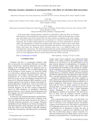
  • 1. Molecular dynamics simulation of nanochannel flows with effects of wall lattice-fluid interactions C. Y. Soong* Department of Aerospace and Systems Engineering, Feng Chia University, Seatwen, Taichung 40724, Taiwan, Republic of China T. H. Yen Graduate School of Defense Science Studies, Chung Cheng Institute of Technology National Defense University, Tahsi, Taoyuan 33509, Taiwan, Republic of China P. Y. Tzeng Department of Aeronautical Engineering, Chung Cheng Institute of Technology, National Defense University, Tahsi, Taoyuan 33509, Taiwan, Republic of China ͑Received 28 March 2007; published 11 September 2007͒ In the present paper, molecular dynamics simulations are performed to explore the effects of wall lattice- fluid interactions on the hydrodynamic characteristics in nanochannels. Couette and Poiseuille flows of liquid argon with channel walls of face-centered cubic ͑fcc͒ lattice structure are employed as the model configura- tions. Truncated and shifted Lennard-Jones ͑LJ͒ 12-6 potentials for evaluations of fluid-fluid and wall-fluid interactions, and a nonlinear spring potential for wall-wall interaction, are used as interatomistic or molecular models. The hydrodynamics at various flow orientation angles with respect to channel walls of lattice planes ͑111͒, ͑100͒, and ͑110͒ are explored. The present work discloses that the effects of key parameters, such as wall density, lattice plane, flow orientation, and LJ interaction energy, have a very significant impact on the nanochannel flow characteristics. The related interfacial phenomena and the underlying physical mechanisms are explored and interpreted. These results are significant in the understanding of nanoscale hydrodynamics, as well as in various applications where an accurate nanoscale flow rate control is necessary. DOI: 10.1103/PhysRevE.76.036303 PACS number͑s͒: 47.61.Fg, 47.27.nd, 47.11.Mn I. INTRODUCTION Compared with flow at conventional conditions, fluid flows at nanoscales have remarkable differences in hydrody- namic characteristics. Interfacial phenomena such as fluid slippage at the wall-fluid interface are significant issues in investigations of nanofluidics. The so-called boundary slip can be classified in various respects, e.g., fluid truly sliding over solid surfaces, apparent slip stemming from surface in- homogeneities, and complex interfacial effects with addi- tional physics, etc. At various wall and fluid conditions, the behaviors of slip, no-slip, and multilayer locking have been observed ͓1͔. Molecular dynamics ͑MD͒ simulation is an ap- propriate approach used widely for dealing with detailed in- terfacial phenomena. Simple flows, such as the Couette and Poiseuille flows in narrow channels with widths of a few molecular diameters, are the most common configurations chosen for MD simulations of nanofluidics. Interesting physical behaviors, such as density layering phenomena and fluid slippage, have been demonstrated in a number of pre- vious MD simulations. At nanoscales, the interfacial phenomena and fluid behav- iors are strongly influenced by the surface conditions of the solid wall. Some previous studies focused on the effects of wall-fluid interaction parameters. For example, Thompson and Robbins ͓2͔ and Thompson and Troian ͓3͔ changed the solid-fluid interaction energy parameter and wall density to study their effects on the slip length. Using MD simulation of thin films of hexadecane, slip characteristics on absorbing surfaces under various conditions were explored ͓4͔. Many studies, such as those of Barrat and Bocquet ͓5,6͔, Cottin- Bizonne et al. ͓7͔, Priezjev et al. ͓8͔, and Cieplak et al. ͓9͔, dealt with the influence of hydrophobicity or wettibility of the wall-fluid interface. For example, Barrat and Bocquet ͓5,6͔ modulated the wettability of the substrate by modulat- ing the magnitude of the attractive force between particles. Soong et al. ͓10͔ performed MD simulations of a nanoscale rotating fluid in a cylindrical container and found nonlinear slip behavior different from that appearing in linear Couette flows, especially around the corner regions of the container. Among the influential factors, the surface roughness is quite significant for interfacial phenomena. A roughened wall can be intentionally fabricated with elements mounted on or grooves indented in solid surfaces. A few previous studies dealt with the effects of surface obstacles or grooves in nanoscale flows, e.g., Couette flow ͓11͔ and electro-osmotic flow ͓12,13͔. In addition, by using a lattice Boltzmann method, Sbragaglia et al. ͓14͔ studied roughness- hydrophobicity coupling in nanochannels with grooved sur- faces. In these cases, the roughness elements considered were of several ␴ ͑molecular length scale͒ in height and width. From a microscopic point of view, even when there is no artificial roughness on the channel walls, the lattice arrange- ment of wall atoms at the wall-fluid interface will produce roughness at the atomistic level. The distance or gap between two neighboring atoms may be of the order of 0.1–1 nm. In a nanochannel tens of nanometers in height, this class of surface roughness is expected to be influential in the fluid flow. The so-called lattice plane or surface orientation of a solid wall characterized by its Miller indices can be a control parameter in nanochannel flows. Considering the flow orien-*Corresponding author. cysoong@fcu.edu.tw PHYSICAL REVIEW E 76, 036303 ͑2007͒ 1539-3755/2007/76͑3͒/036303͑14͒ ©2007 The American Physical Society036303-1
  • 2. tation with respect to the lattice structure, the flow angle becomes another significant parameter. In the literature, one can find only a few studies on the effects of crystal-fluid interaction on material bulk properties and thermodynamics ͓15,16͔. Galea and Attard ͓17͔ studied the effect of solid atomistic roughness on the slip length by changing the wall density of a fixed crystal plane, the face-centered cubic ͑fcc͒ ͑100͒ plane. They found a nonmonotonic trend of slip length variation with changes in wall density. However, the influ- ence of the lattice plane on the fluid flows in nanochannels has not been investigated yet. Furthermore, the flow orienta- tion with respect to the lattice structure has not been taken into account in previous investigations of nanoscale fluid flows. The objective of the present study is to explore the effects of the wall crystal-fluid interactions in nanochannels by us- ing molecular dynamics simulation. Couette and Poiseuille flows with channel walls of fcc lattice structure are employed as the model configurations. Truncated and shifted Lennard- Jones ͑LJ͒ potentials for evaluation of the fluid-fluid and the wall-fluid interactions, and a nonlinear spring potential for wall-wall interaction, are used. With liquid argon of densities ␳f,b␴3 =0.81 and 0.95 as the model fluid, various wall densi- ties ␳w␴3 =1.0–4.0 and wall-fluid interaction parameters ␧wf /␧=0.4–1.0 are considered. The hydrodynamics at vari- ous surface and flow orientation angles with respect to the channel walls of the surfaces fcc ͑111͒, ͑100͒, and ͑110͒ are explored. II. METHODOLOGY The channel-fluid system under consideration is com- posed of fluid molecules confined between two parallel pla- nar walls separated with a height H. Both Couette and Poi- seuille flows are investigated in the present study. Periodic boundary conditions are imposed on the upstream and down- stream boundaries ͑X direction͒ and two sides ͑Y direction͒ of the computational domain of size 16␴ϫ16␴ϫ21.8␴. Couette flow is a planar fluid layer with the upper wall mov- ing at a constant velocity Uw along the streamwise direction ͑X͒, whereas in Poiseuille flow, an external force stemming from the pressure gradient fp in the X direction is applied to the fluid particles. The position of the first layer of molecules in the solid lattice is set as the reference for the Z axis. In this study, with emphasis on the interfacial phenomena and related physical mechanisms, a simple fluid commonly used in MD simulations, liquid argon, is employed as the model fluid. In addition, for convenience, we employ a hy- pothetical solid wall of fcc lattice structure with a nonlinear spring model of interaction between wall atoms. The details of the MD model are as follows. A. Potential models In the present MD simulations, the pair potential between fluid-fluid and fluid-wall atoms is governed by truncated and shifted Lennard-Jones potentials, viz., ␾␣␤͑rij͒ = Ά4␧␣␤ͫͩ␴␣␤ rij ͪ12 − c␣␤ͩ␴␣␤ rij ͪ6 − ͩ␴␣␤ rc ͪ12 + c␣␤ͩ␴␣␤ rc ͪ6 ͬ, rij ഛ rc, 0, rij Ͼ rc, · ͑1͒ where the parameters ␧␣␤ and ␴␣␤ are, respectively, the en- ergy and length scales for the interaction of species ␣ and ␤, and rij is the separation distance between the particles i and j. The Lorentz-Berthelot mixing rule is adopted to evaluate interaction parameters pertaining to two dissimilar species, i.e., ␧␣␤=ͱ␧␣␣␧␤␤ and ␴␣␤=͑␴␣␣+␴␤␤͒/2. The interaction parameters between solid and fluid particles are ␧wf =ͱ␧ff with ␧ww=1.0 and ␴wf =͑␴ww+␴ff͒/2. In the following text, the fluid-fluid parameters ␧ff and ␴ff are employed as the characteristic molecular energy and length scales. The pa- rameter c␣␤ is the coefficient of the attraction term. For com- mon LJ fluids, the coefficient cff =1.0 ͓2,3͔ is defined, while for a more cohesive LJ fluid, cff has a higher value, e.g., cff =1.2 ͓4,5͔. In the present study, these two kinds of inter- actions between fluid atoms are both considered. For com- parison, we consider the special case of cff =0, which corre- sponds to the so-called Weeks-Chandler-Anderson ͑WCA͒ model with attraction ignored ͓18͔. To save computational time, as in the usual MD simulations in previous work, a cutoff distance rc is chosen for each model, beyond which the intermolecular forces are neglected for the small interac- tions between molecules at relatively large distances. The cutoff distance is rc=2.5␴ for the usual LJ flow, and rc =2.8␴ for the more cohesive LJ flow. For comparison, we also perform a few computations using the WCA model, whose cutoff distance is rc=ͱ6 2␴. The mass of wall atoms is assumed to be identical to that of the fluid atoms. The wall- fluid interaction potential ␾wf has a similar form as Eq. ͑1͒ but with the parameters denoted by ␧wf, ␴wf, and cwf, where cwf =1.0. Liquid molecules are initially arranged at the lattice sites, and the walls are composed of four layers of atoms fixed as a face-centered cubic lattice structure. Each wall atom may oscillate about its lattice site; a nonlinear spring potential for a fcc lattice, ␾ww͑S͒ = ͑H1/2͒S2 + ͑H1/4dcr 2 ͒S4 + ͑H1/6dcr 4 ͒S6 , ͑2͒ is employed, in which the parameters H1, H2, and H3 are the spring constants; S stands for the displacement of a wall SOONG, YEN, AND TZENG PHYSICAL REVIEW E 76, 036303 ͑2007͒ 036303-2
  • 3. molecule from its lattice site; and the parameter dcr 2 is the critical mean-square displacement of the wall atom, which is determined according to the Lindemann criterion for melt- ing, dcr 2 Ͻ0.023R0 2 . We use dcr 2 =0.01R0 2 , where R0 is the nearest-neighbor distance. The density of the solid wall can be expressed as ␳w=4/a3 , where a is the unit cell length. The equilibrium nearest-neighbor spacing R0 can be expressed as a/ͱ2. The LJ length scale of wall atoms, ␴ww, can be evalu- ated by the following relation ͓17͔: ␴ww = R0/1.09. ͑3͒ The roughness of the solid surface alters with the unit cell length a, and, therefore, the interaction length scale of the wall molecules, ␴ww, is changed. With the length parameters of the fluid molecules and wall atoms, ␴ff and ␴ww, the wall- fluid interaction length scale ␴wf can be evaluated according to the Lorentz-Berthelot mixing rule ␴wf =͑␴ww+␴ff͒/2. B. Thermostat Khare et al. ͓19͔ compared two approaches for keeping the system temperature constant, one with thermostat applied only to the wall atoms and the fluid particles within the thin layer closest to the walls, and the other with the thermostat applied to the molecules in the entire fluid region. Based on their results, the former thermostat was recommended. In the investigation of Hagen-Poiseuille flow through a cylindrical pore, Heinbuch and Fischer ͓1͔ disclosed that the flow pat- tern depends on the wall-fluid interaction, the driving force, the treatment of the thermostat, and the thermodynamic state. To attain the statistical formalism of the ensemble, the Nosé- Hoover thermostat ͓20͔ is adopted. For the fluid particles adjacent to the walls, since there are only a few fluid par- ticles within the near-wall region of width 0.5␴, the thermo- stat is actually applied to the particle motion in the Y direc- tion within an outer layer of Y =͑0.6–1.1͒␴. For the solid wall, a three-directional Nosé-Hoover thermostat is adopted. C. Governing parameters in simulations In the present study, the fluid-fluid interaction energy ␧ff and length ␴ff, the conventional molecular units, are taken as the molecular energy and length scales, and the notations ␧ and ␴ are used for brevity. The notation m stands for the mass of the molecule, ␴ for the length scale, ␧ for the energy scale, ␶=͑m␴2 /␧͒1/2 for the time scale, and ␧/kB for the tem- perature scale. For liquid argon, the scales are ␴=3.405 Å, ␧=119.8kB, and ␶Ӎ2.2ϫ10−12 s. The dimensions of density, velocity, force, and viscosity are ␴−3 , ␴/␶, ␧/␴, and ␧␶/␴3 , respectively. The Newtonian equation of motion of the mol- ecules is integrated by using a velocity Verlet algorithm with a time step of 3ϫ10−3 ␶. In previous work ͓3͔, it is claimed that, in the case of Uw=1.0␴/␶, the time periods of 100␶ for stabilization and 200␶ for data sampling and averaging are required to reduce thermal fluctuations. In the present study, the time period of 300␶ for each simulation is sufficient to reach this end. In the present flow model, the channel height H=21.8␴, the numbers of fluid atoms Nf =4301 or 5112, the numbers of wall atoms Nw=1120–2896, the wall densities ␳w␴3 =1.0–4.0, the fluid densities ␳f,b␴3 =0.81 and 0.95, the tem- peratures kBT/␧=1.0 and 1.1, and the viscosities ␮␴3 /␧␶ (100) (111) (110) (b) fcc lattice (a) Nanochannel model (c) Surface orientation (d) Flow orientation Flow Direction X Y Z θ θ θ θ= 0 θ= 0 θ= 0 FIG. 1. ͑Color online͒ Flow channel models, surface orientation, and flow orientation. ͑a͒ Nanochannel model; ͑b͒ face-centered cubic crystal lattice; ͑c͒ surface orientation or crystal plane; ͑d͒ flow orientation. MOLECULAR DYNAMICS SIMULATION OF NANOCHANNEL … PHYSICAL REVIEW E 76, 036303 ͑2007͒ 036303-3
  • 4. =2.14 for liquid Ar and about 5 for a more cohesive fluid are considered. The interaction energy ␧wf spans from 0.4 to 1.0, and ␧wf =1.0 is used if not specified. The interaction length scale ␴wf is calculated based on the Lorentz-Berthelot mix- ing rule as mentioned in Sec. II A. Three surface orientations, fcc ͑111͒, fcc ͑100͒, and fcc ͑110͒, are considered. Both surfaces ͑111͒ and ͑100͒ have closely packed atomistic structures and small distances be- tween neighboring atoms; whereas the lattice plane ͑110͒ has a relatively sparse structure with atomistic trenches appear- ing in the first layer of atoms which contact the fluid par- ticles. Among these three surface orientations, the plane fcc ͑111͒ is the smoothest, fcc ͑110͒ is the roughest, and fcc ͑100͒ lies in between. In addition, wall-fluid interactions in the presence of various flow orientations with respect to the crystal plane are explored. Figure 1͑a͒ shows the nanochan- nel model; Fig. 1͑b͒ the fcc lattice structure; Fig. 1͑c͒ the lattice planes or surface orientations; and Fig. 1͑d͒ the defi- nition of the flow orientation angle and the global view of the surface and flow orientations. III. RESULTS AND DISCUSSION Before simulations for systematic study, the validation of the present MD simulation was examined. Figure 2 presents a comparison of the present with the previous results ͓4͔, in which only fcc ͑111͒ was studied. Basically, our simulations agree quite well with the previous ones. This demonstrates the appropriateness of the present MD simulation code. A. Density profiles In Fig. 3͑a͒, a typical example of density layering phe- nomenon associated with nanoscale fluid behavior is pre- sented. The fluid density is oscillatory in the near-wall region and meets the bulk fluid density in the off-wall core region. Figures 3͑b͒–3͑e͒ show closeup views of near-wall density profiles in Couette flows with various surface and flow ori- entations. It is observed from the results at ␪=0° in Fig. 3͑b͒ that the density profiles for the two closely packed lattice planes, ͑111͒ and ͑100͒, are very similar, both qualitatively and quantitatively. The relatively sparse one, ͑110͒, however, has peaks a little lower and locations closer to the wall. In the case of lattice plane ͑110͒, a relatively stronger momen- tum and energy exchange between wall and fluid atoms oc- curs, and the fluid atoms reflect from the wall with less mo- mentum and energy, which causes the locations of the density peaks to move toward the wall. This demonstrates the influence of the wall lattice plane. The data presented in Figs. 3͑c͒–3͑e͒ disclose that the flow orientation has little influence on the density profiles. It can be elucidated that the density layering is a consequence of interactions between wall and fluid particles even when the bulk fluid is stationary. Therefore, the density layering is regarded as a fluid static feature in the sense of bulk flow; it has little relation to the flow direction. To explore the influences of the wall-fluid interaction pa- rameters, the near-wall density profiles at various conditions Z/H U/Uw 0 0.2 0.4 0.6 0.8 1 0 0.2 0.4 0.6 0.8 1 0.6 1.0 1 0.6 0.75 4 wf -1 wf -1 w 3 Thompson & Troian, 1997 f, b 3 =0.81, kBT -1 =1.1f,b 3 = 0.81, cff =1.0, kBT/ = 1.1 wf / wf / w 3 Z/H fcc(111) = 0° w u U FIG. 2. ͑Color online͒ Verification of the simulation by compari- son of the present results with the previous MD results ͓3͔ for Couette flow in a nanochannel of the fcc ͑111͒ wall surface. 0 0.25 0.5 0.75 1 0 1.5 3 4.54.5 3.0 1.5 0.0 0 0.25 0.5 0.75 1.0 f 3 Z / H f,b 3 = 0.81, w 3 = 2.76, cff =1.0 kBT/ =1.1, wf / =1.0, wf / = 0.867 fcc(111) = 0° (a) 0 1.5 3 4.5 0 1.5 3 4.5 0 1.5 3 4.5 0 0.5 1 1.5 2 2.5 0 1.5 3 4.5 Z/ fcc(111) fcc(100) fcc(110) f,b 3 = 0.81, w 3 = 2.76 kBT/ = 1.1 fcc(111) fcc(100) fcc(110) (b) (c) (d) (e) 0º 15º 30º 45º 0º 15º 30º 45º 0º 15º 30º 60º 90º f 3 FIG. 3. Effects of lattice plane and flow orientation on fluid density distributions. ͑a͒ Typical density distribution; ͑b͒ effects of lattice plane; ͑c͒–͑e͒ effects of flow orientation. SOONG, YEN, AND TZENG PHYSICAL REVIEW E 76, 036303 ͑2007͒ 036303-4
  • 5. are shown in Fig. 4, where the results with ␳f,b␴3 =0.81, cff =1.0, kBT/␧=1.1, ␧wf /␧=1.0, and ␳w␴3 =1.3–4.0 are pre- sented in Fig. 4͑a͒ for reference. Generally, the results shown in Fig. 4 reveal that a higher wall density leads to more remarkable density layering phenomenon, with enhancement of the peak values as well as shift of the peak locations toward the wall. Compared with the baseline cases in Fig. 4͑a͒, change in cff results in little change as shown in Fig. 4͑b͒. It can be observed that, in Figs. 4͑b͒ and 4͑c͒, increase in fluid density and reduction in fluid temperature both in- crease the level of the fluid density. The effects of the inter- action parameter ␧wf on the density layering phenomenon at ␳w␴3 =1.3 are presented in Fig. 4͑d͒. Increase in the wall- fluid interaction parameter ␧wf /␧ implies an enhanced energy exchange between wall and fluid, and, in turn, the data show that the density peaks are pronounced and their locations shifted toward the wall. For the most roughened case, fcc ͑110͒, the density layering is weaker. Figure 5 presents quantities for characterizing the density layering phenomenon, i.e., the amplitude Apϵ␳͑Zp͒/␳f,b and the location Zp of the first peak in the density profile. In Fig. 5͑a͒, the rough surface fcc ͑110͒ has monotonically increas- ing amplitude Ap as the wall density increases; while for the two relatively smoother surfaces, fcc ͑111͒ and ͑100͒, Ap presents different behaviors, and, especially, a nonmonotonic trend appears in the range of ␳w␴3 around 3. The reason for this nonmonotonic variation of Ap can be addressed as fol- lows. The density oscillation can be enhanced with an in- crease in wall density but, at the same time, the characteristic length or influence range of the wall-fluid interaction ␴wf decreases with increasing ␳w␴3 . These two counter effects may make the change in Ap nonmonotonic. For the more cohesive fluid with cff =1.2, as shown in Fig. 5͑b͒, the same trend is obtained. For comparison, simulations with the WCA model ͑cff =0͒ are plotted, and the predictions reveal f 3 0 1.5 3 4.5 1.3 2.3 4.0 w fcc100 Z -1 f 3 0 0.5 1 1.5 2 2.5 0 1.5 3 4.5 1.3 2.3 4.0 w fcc110 f 3 0 1.5 3 . 1.3 2.3 4.0 wf bulk = 0.81 cij = 1.0 T=1.1 fcc111 w 3 1.3 2.3 4.0 f,b 3 = 0.81 cff = 1.0 kBT/ = 1.1 fcc(100) fcc(111) = 0° 4.5 3.0 1.5 0.0 fcc(110) 0 0.5 1.0 1.5 2.0 2.5 Z / 4.5 3.0 1.5 0.0 4.5 3.0 1.5 0.0 f 3 f 3 0 1.5 3 1.3 2.3 4.0 w f bulk = 0.81 cij = 1.2 T=1.1 fcc111 f 3 0 1.5 3 4.5 1.3 2.3 4.0 w fcc100 Z -1 f 3 0 0.5 1 1.5 2 2.5 0 1.5 3 4.5 1.3 2.3 4.0 w fcc110 fcc(110) fcc(100) fcc(111) = 0° Z / f,b 3 = 0.81 cff = 1.2 kBT/ = 1.1 w 3 1.3 2.3 4.0 0 0.5 1.0 1.5 2.0 2.5 4.5 3.0 1.5 0.0 4.5 3.0 1.5 0.0 4.5 3.0 1.5 0.0 f 3 f 3 0 1.5 3 4.5 1.3 2.3 4.0 w f bulk = 0.95 cij = 1.2 T=1.0 fcc111 f 3 0 1.5 3 4.5 1.3 2.3 4.0 w fcc100 Z -1 f 3 0 0.5 1 1.5 2 2.50 1.5 3 4.5 1.3 2.3 4.0 w fcc110 Z / fcc(100) fcc(111) 0 0.5 1.0 1.5 2.0 2.5 w 3 1.3 2.3 4.0 f,b 3 = 0.95 cff = 1.2 kBT/ = 1.1 = 0° fcc(110) 4.5 3.0 1.5 0.0 4.5 3.0 1.5 0.0 4.5 3.0 1.5 0.0 f 3 Z / 0 5 3 5 0 5 3 5 0 0.5 1 1.5 2 2.5 0 5 3 5 fcc(111) fcc(100) fcc(110) w / 0.4 0.6 0.8 1.0 f 3 4.5 3.0 1.5 0.0 f,b 3 = 0.95 w 3 = 1.33 cff = 1.2 kBT/ = 1.0 = 0° 4.5 3.0 1.5 0.0 4.5 3.0 1.5 0.0 0 0.5 1.0 1.5 2.0 2.5 Z / (a) (b) (c) (d) FIG. 4. Near-wall density profiles at flow orientation angle ␪=0° under various conditions. MOLECULAR DYNAMICS SIMULATION OF NANOCHANNEL … PHYSICAL REVIEW E 76, 036303 ͑2007͒ 036303-5
  • 6. that, without accounting for the attractive force between mol- ecules, the fluid density oscillation is little influenced by the wall density. The correlation of the location Zp of the first density peak with ␳w␴3 is presented in Fig. 5͑c͒. In general, the location of the density peak is not sensitive to the change in wall density, especially in the intermediate range of ␳w␴3 , where the location of the first fluid density peak remains almost unchanged. The surface fcc ͑110͒ is of a more aniso- tropic nature and is rougher than the other two surface ori- entations. For the lattice plane fcc ͑110͒, the increments in Ap with increasing ␳w␴3 are larger than for the other two sur- faces. This enhancement of the density layer phenomenon at higher Ap is caused by the stronger influences of the second layer of wall atoms that are exposed in the trenches of first- layer structures, and also have the smallest distance from the first layer of wall-fluid particles. As the wall density in- creases, the density layering phenomenon becomes more pronounced with decreasing distance between the first and second layers of wall atoms. B. Velocity profiles Figure 6͑a͒ shows the velocity profiles in the Couette flow with solid walls of various lattice planes but a fixed flow orientation angle ␪=0°. The results reveal that the velocity distributions are basically linear, but distinct from each other in boundary slip. The most notable fluid slippage at the wall- fluid interface is that for the most packed surface ͑111͒, and least for the surface ͑100͒. The lattice plane ͑110͒ with ato- mistic trenches may trap fluid particles via strong wall-fluid interactions. This fact leads to a strong multilayer-sticking phenomenon characterized by a negative slip length. Figure 6͑b͒ shows the MD predictions of the velocity distributions in the Poiseuille flow driven by a constant force fp =0.02␧/␴. The velocity profiles for ͑111͒, ͑100͒, and ͑110͒ are of the same curve type but, similar to the observations on Couette flow, they deviate from each other in different de- grees of fluid slippage appearing at the wall-fluid interface. Each of the three fcc lattice planes considered in the present work has its own symmetric nature. This can be seen w 3 Ap 0 1 2 3 4 5 1 2 3 4 5 6 fcc111 fcc100 fcc110 fcc111 (WCA) f = 0.95 -3 , cij = 1.2 ( = 0 o ) w 3 fcc(111) fcc(100) fcc(110) fcc(111) (WCA model) pA = 0°f,b 3 = 0.95, cff = 1.2, w 3 Ap 0 1 2 3 4 5 1 2 3 4 5 6 fcc111 fcc100 fcc110 f= 0.81 -3 , cij= 1.0 ( = 0 o ) fcc(111) fcc(100) fcc(110) pA w 3 = 0°f,b 3 = 0.81, cff = 1.0, w 3 Zpeak -1 1 2 3 4 0.5 1 1.5 2 fcc111 fcc100 fcc110 f =0.95 -3 , cij = 1.2 f =0.81 -3 , cij = 1.0 ( = 0 o ) fcc(111) fcc(100) fcc(110) = 0° pz w 3 f,b 3 = 0.95, cff = 1.2 f,b 3 = 0.81, cff = 1.0 (a) (b) (c) FIG. 5. First density peak Ap of the fluid density distribution in ͑a͒ usual LJ fluid ͑cff =1.0͒ and ͑b͒ more cohesive LJ fluid ͑cff =1.2͒. ͑c͒ Locations of the peak Ap. fcc(111) fcc(100) fcc(110) w u U f,b 3 =0.81, kBT/ =1.1 w 3 =2.76 Z / H fcc(111) fcc(100) fcc(110) = 0° 0 0.25 0.5 0.75 1.0 1.0 0.8 0.6 0.4 0.2 0.0 fcc(111) fcc(100) fcc(110) f,b 3 =0.81, kBT/ =1.1, w 3 =2.76 Z / H = 0° fcc(110) fcc(111) fcc(100) 0 0.25 0.5 0.75 1.0 1.0 0.8 0.6 0.4 0.2 0.0 u (a) (b) FIG. 6. Effects of lattice plane on flow velocity distributions at ␪=0°, ␳w␴3 =2.76, ␳f,b␴3 =0.81, kBT/␧=1.1. ͑a͒ Couette and ͑b͒ Poiseuille flow. SOONG, YEN, AND TZENG PHYSICAL REVIEW E 76, 036303 ͑2007͒ 036303-6
  • 7. from the surface ͑first-layer͒ atomistic pattern shown in Fig. 1. For the lattice plane ͑111͒, the first layer of atoms has a line of symmetry at ␪=30°, and flow orientations of ␪=0°, 15°, 30°, and 45° are explored. Similarly, the first layer of the ͑100͒ plane has a line of symmetry at ␪=45°, and flow ori- entations of ␪=0°, 15°, 30°, and 45° are studied. As to the plane ͑110͒, it is symmetric with respect to the line ␪=90°. There are parallel trenches of atomistic scale along the direc- tion of ␪=90°; therefore, flow characteristics at the flow angles ͑␪͒ between 0° and 90° are simulated to examine the effects of flow orientation. Since the second and third layers of solid-wall atoms may also give contributions to the inter- facial phenomenon, the distances between atomistic layers are also significant. Taking the wall density ␳w␴3 =2.76 as an illustrative example, the distances between the neighboring layers of surfaces ͑111͒, ͑100͒, and ͑110͒ are, respectively, 1.1314␴, 0.9798␴, and 0.6928␴, which are within the range of the cutoff distance ␴c=2.5␴ in MD simulations. It implies that, in addition to the first layer, the wall atoms of the sec- ond and third layers will also have notable influences on the fluid particles near the interface. However, the wall atoms in the first layer contact the fluid directly and thus dominate the wall-fluid interactions. The present MD predictions of velocity distributions dem- onstrate that this class of nanochannel flows can be signifi- cantly influenced by the flow orientation. Figures 7͑a͒ and 7͑b͒, respectively, show the Couette and Poiseuille flows of the usual LJ fluids with cff =1.0, ␳w␴3 =2.76, ␳f,b␴3 =0.81, and kBT/␧=1.1. For both flows, the MD results reveal that, among the three lattice planes, the flow with a channel wall of surface ͑100͒ is most insensitive to the variation of the flow orientation. The most roughened and anisotropic surface ͑110͒ with flow orientation angles between 0° and 90° gen- erates noticeable and monotonic effects on the flow field. Figure 7͑c͒ presents the velocity profiles in the same condi- tions as above, but with the wall density increased up to ␳w␴3 =3.0–3.3. Comparing Fig. 7͑c͒ with Fig. 7͑b͒, the hy- drodynamic behaviors at ␳w␴3 =3.0–3.3 are quite similar to those in the cases of ␳w␴3 =2.76, but the fluid slippage and the flow orientation effects seem enhanced in the presence of higher wall density. C. Slip length The fluid slippage at the solid-liquid interface is an im- portant hydrodynamic characteristic in dealing with nanos- u 0 O 15 O 30 O 45 O fcc(100) f,b 3 =0.81, kBT/ =1.1 w 3=2.76, cff =1.0 0° 15° 30° 45° 0 15O 30O 45O fcc(111) 0° 15° 30° 45° f,b 3 =0.81, kBT/ =1.1 w 3 =2.76, cff =1.0 0 O 30 O 45 O 75O 90O fcc(110) f,b 3 =0.81, kBT/ =1.1 w 3 =2.76, cff =1.0 0° 30° 45° 75° 90° Z / H 0.0 0.25 0.5 0.75 1.0 1.0 0.8 0.6 0.4 0.2 0.0 1.0 0.8 0.6 0.4 0.2 0.0 1.0 0.8 0.6 0.4 0.2 0.0 u u Z / H fcc(111) 0° 15° 30° 45° cff =1.0 f,b 3=0.81, kBT/ =1.1 w 3=3.0, cff =1.0 fcc(100) f,b 3=0.81, kBT/ =1.1 w 3=3.0, cff =1.0 0° 15° 30° 45° fcc(110) f,b 3 =0.81, kBT/ =1.1, cff =1.0 0° 3.0 45° 3.3 75° 3.2 90° 3.2 w 3 Z / H u 1.0 0.8 0.6 0.4 0.2 0.0 0.0 0.25 0.5 0.75 1.0 1.0 0.8 0.6 0.4 0.2 0.0 1.0 0.8 0.6 0.4 0.2 0.0 u u 0 O 30 O 45O 75O 90 O fcc(110) f,b 3=0.81, kBT/ =1.1 w 3=2.76, cff =1.0 0° 30° 45° 75° 90° 0 15 30 45 fcc(111) f,b 3=0.81, kBT/ =1.1, w 3=2.76 0° 15° 30° 45° cff =1.0 4 0 o 15 O 30 O 45O fcc(100) f,b 3=0.81, kBT/ =1.1, w 3=2.76, cff =1.0 0° 15° 30° 45° u 0.0 0.25 0.5 0.75 1.0 1.0 0.8 0.6 0.4 0.2 0.0 1.0 0.8 0.6 0.4 0.2 0.0 1.0 0.8 0.6 0.4 0.2 0.0 u u (a) (b) (c) FIG. 7. Effects of flow orientation on ͑a͒ Couette and ͑b͒ Poiseuille flow velocity distributions at cff =1.0, kBT/␧=1.1, ␳f,b␴3 =0.81, and ␳w␴3 =2.76; ͑c͒ Poiseuille flow velocity distributions at cff =1.0, kBT/␧=1.1, ␳f,b␴3 =0.81, and ␳w␴3 =3.0–3.3. MOLECULAR DYNAMICS SIMULATION OF NANOCHANNEL … PHYSICAL REVIEW E 76, 036303 ͑2007͒ 036303-7
  • 8. cale flows. The slip length Ls, as a measure of fluid slippage, is defined in Navier’s slip formula US=LS͑dU/dn͒w, where US stands for the slip velocity and ͑dU/dn͒w for the wall velocity gradient in the normal direction ͑n͒. The effects of wall and fluid properties and the wall-fluid interaction pa- rameters on the slip length are considered. In Fig. 8, the effects of wall density variation on the slip length in the Couette flow are presented. The slip length is obtained by linear fit of the velocity data but, to reduce the statistical noise, with the data in near-wall regions of thickness 1.5␴ excluded. The multilayer-sticking phenomenon is character- ized by a negative slip length. In this situation, the fluid particles in a thin region adjacent to the solid wall are im- mobile. Minimum slip length may occur when the wall and fluid densities are low and commensurate. As mentioned in a previous study ͓12͔, the slip length varies with wall density in a nonmonotonic manner. A local minimum appears when the wall density ␳w␴3 lies in a range around 3. Generally speaking, a smooth and/or high-density wall tends to gener- ate a large slip length. This nonmonotonic dependence of wall density is inferred as a consequence of the complicated wall-fluid interaction mechanisms mentioned in the discus- sion of the results shown in Fig. 5. To explore the slip length correlation more extensively, Couette flows of cohesive flu- ids ͑cff =1.2͒ with bulk fluid density ␳f,b␴3 =0.95 are studied, and the MD results with variations in wall density are pre- sented in Fig. 8͑b͒. The data shown in both figures have similar qualitative trends. For the rougher channel wall of fcc ͑110͒ with flow orientation angle ␪=0°, mild changes in slip length are presented; whereas a nonmonotonic nature ap- pears in the cases of smoother walls, i.e., fcc ͑111͒ and ͑100͒. To further examine the slip length variation, simulations for the cases of fcc ͑111͒ using the WCA model ͑cff =0͒ are performed. It is interesting to note that the nonmonotonic behavior appears in the simulations with cff =0, 1.0, and 1.2, which correspond to fluids without interparticle attraction force, normal LJ fluids, and more cohesive LJ fluids, respec- tively. This observation implies that the attraction between fluid particles is irrelevant to the mechanism of this anoma- lous behavior of wall-density dependence. The interaction energy parameter ␧wf is also one of the influential factors on the wall-fluid interaction. A strong in- teraction potential enhances the wall-fluid exchange of mo- mentum and energy and tends to alleviate the discontinuity at the interface. Therefore, the slip length decreases monotoni- cally with increasing ␧wf as the MD predictions show in Fig. 9. There, variations of the slip length with the interaction parameter ␧wf at the wall densities ␳w␴3 =1.33 and ␳w␴3 =4.0 are plotted in Figs. 9͑a͒ and 9͑b͒, respectively. In all cases considered, the lattice plane ͑111͒ always results in the largest fluid slippage among the three surfaces. For the lower wall density considered in Fig. 9͑a͒, since the bulk fluid den- 4 4 fcc111 fcc100 fcc110 ( = 0O ) f = 0.81 -3 , Cij = 1.2, kB T/ = 1.1 f,b 3 = 0.81, cff = 1.0, kBT/ = 1.1 fcc(111) fcc(100) fcc(110) = 0° sL 0 1 2 3 4 5 12 10 8 6 4 2 0 -2 -4 w 3 sL 4 fcc(111) fcc(111)(WCA model) fcc(100) fcc(110) f,b 3 = 0.95, cij= 1.2, kBT/ =1.0 ( =0o ) = 0° f,b 3 = 0.95, cff = 1.2, kBT/ = 1.0 w 3 0 1 2 3 4 5 12 10 8 6 4 2 0 -2 -4 (a) (b) FIG. 8. Variations of slip length in Couette flow at ␪=0°, kBT/␧=1.1, and ␳f,b␴3 =0.95 with the wall density and lattice plane. ͑a͒ Usual LJ fluid ͑cff =1.0͒ and ͑b͒ cohesive LJ fluid ͑cff =1.2͒. Simulations with WCA model are presented for comparison. fcc(111) fcc(100) fcc(110) f,b 3 = 0.95 ,cij= 1.2 w= 1.33 -3 , kBT/ = 1.0 ( =0o ) = 0° wf / sL f,b 3 = 0.95, cff = 1.2 w 3 = 1.33, kBT/ = 1.0 0.2 0.4 0.6 0.8 1.0 1.2 35 30 25 20 15 10 5 0 -5 fcc(111) fcc(100) fcc(110) f,b 3 = 0.95 ,cij = 1.2 w= 4.0 -3 , kBT/ = 1.0 ( = 0 o ) = 0° sL f,b 3 = 0.95, cff = 1.2 w 3 = 4.0, kBT/ = 1.0 35 30 25 20 15 10 5 0 -5 wf / 0.2 0.4 0.6 0.8 1.0 1.2 (a) (b) FIG. 9. Variation of slip length with the interaction parameter ␧wf /␧ for LJ fluid of cff =1.2 and ␳f,b␴3 =0.95 at ␪=0°, kBT/␧ =1.0, and the wall density of ␳w␴3 =͑a͒ 1.3 and ͑b͒ 4.0. SOONG, YEN, AND TZENG PHYSICAL REVIEW E 76, 036303 ͑2007͒ 036303-8
  • 9. sity ␳f,b␴3 =0.95 is close to ␳w␴3 =1.33, the strong wall-fluid interaction results in multilayer sticking phenomenon or a negative slip length. As the wall density increases up to ␳w␴3 =4.0, the slip length is generally increased, as shown in Fig. 9͑b͒. The behavior of the plane fcc ͑110͒ is an excep- tion. Compared with the data shown in Fig. 9͑a͒, the slip length at ␳w␴3 =4.0 does not increase but decreases. This different behavior can be elucidated with the curve for fcc ͑110͒ shown in Fig. 8͑b͒. The orientation of the flow over solid surfaces may have significant impact on interfacial phenomena. The flow orien- tation is characterized by the flow angle defined in Fig. 1. Among the three lattice planes considered, fcc ͑110͒ is the most anisotropic and rough one, and is employed to examine the flow orientation effects in Fig. 10. The three angles 0°, 45°, and 90° designate the situations of flow across the sur- face molecular trenches, the flow over the surface at the angle 45° with the atomistic trenches, and the fluid flow along the trenches, respectively. Figure 10͑a͒ shows the MD results for Ls/␴ versus ␳w␴3 for the usual LJ fluid with ␳f,b␴3 =0.81, cff =1.0, and kBT/␧=1.1. With the above as the baseline cases cff is changed to 1.2 in Fig. 10͑b͒, then kBT/␧ is changed to 1.0 in Fig. 10͑c͒, and finally, in Fig, 10͑d͒, the fluid bulk density ␳f,b␴3 is further changed from 0.81 to 0.95. Generally speaking, for the lattice plane fcc ͑110͒, the results in Fig. 10 demonstrate that the fluid slippage is strongly in- fluenced by the flow orientation as well as the wall density, and the slip length increases monotonically with the flow orientation angle ͑␪͒. The slip length at flow angle ␪=90° is largest; while the slip lengths at the flow angles ␪=0° and 45° are lower, and these two flow configurations have quite similar characteristics. The fluid slippage is more pro- nounced with high wall density, or ␳w␴3 Ͼ2. The results also show that the fluid slippage at the orientation angle ␪=90° can be highly enhanced by raising the fluid bulk density ␳f,b␴3 up to 0.95. D. Similarity of interfacial phenomena and poiseuille flow rates Figure 11 presents variations in slip length under the in- fluence of wall density, lattice plane, and flow orientation. In particular, this section emphasizes the comparison of fluid slippage phenomena in Couette and Poiseuille flows, and ex- plores the possible similarity between the interfacial phe- nomena in nanochannel flows. In general, all the data dem- onstrate similarity in Couette and Poiseuille flows, both qualitatively and quantitatively. For a detailed exploration, Fig. 11͑a͒ shows that this similar trend exists for the more cohesive LJ fluid flow over various lattice planes at the ori- entation angle ␪=0°. In Fig. 11͑b͒, the results for the plane ͑110͒ with flow orientation angles ␪=0°, 45°, and 90° are presented. With respect to the variations of wall density, the results in Figs. 11͑a͒ and 11͑b͒ show quite good agreement of the slip lengths in the two flows at various conditions. With focus on the influence of the flow orientation angle, Fig. 11͑c͒ plots the slip length correlations for both the Cou- ette and Poiseuille flows. At flow orientation angles between 0° and 45°, the slip length over the lattice plane ͑111͒ is the largest among the three surfaces, and varies in a periodic w 3 Ls/ 0 1 2 3 4 5 -6 -4 -2 0 2 4 6 8 10 0o 45 o 90 o f 3 = 0.81, cij =1.0, kB T/ =1.1 Fcc(110) sL 0 1 2 3 4 5 10 8 6 4 2 0 -2 -4 -6 fcc(110) = 0° = 45° = 90° f,b 3 = 0.81, cff = 1.0, kBT/ = 1.1 w 3 w 3 Ls/ 0 1 2 3 4 5 -6 -4 -2 0 2 4 6 8 10 0 o 45 o 90 o f 3 = 0.81, cij =1.2, kB T/ =1.1 Fcc(110) f,b 3 = 0.81, cff = 1.2, kBT/ = 1.1 sL 10 8 6 4 2 0 -2 -4 -6 0 1 2 3 4 5 fcc(110) = 0° = 45° = 90° w 3 w 3 Ls/ 0 1 2 3 4 5 -6 -4 -2 0 2 4 6 8 10 0 o 45o 90o f 3 = 0.81, cij=1.2, kBT/ =1.0 Fcc(110) 0 1 2 3 4 5 sL 10 8 6 4 2 0 -2 -4 -6 fcc(110) = 0° = 45° = 90° f,b 3 = 0.81, cff = 1.2, kBT/ = 1.0 w 3 w 3 Ls/ 0 1 2 3 4 5 -6 -4 -2 0 2 4 6 8 10 0o 45o 90 o f 3 = 0.95, cij =1.2, kB T/ =1.0 Fcc(110) sL 10 8 6 4 2 0 -2 -4 -6 0 1 2 3 4 5 fcc(110) = 0° = 45° = 90° f,b 3 = 0.95, cff = 1.2, kBT/ = 1.0 w 3 (a) (b) (c) (d) FIG. 10. Variations of slip length with wall density and flow orientation in a nanochannel with fcc ͑110͒ wall surface. MOLECULAR DYNAMICS SIMULATION OF NANOCHANNEL … PHYSICAL REVIEW E 76, 036303 ͑2007͒ 036303-9
  • 10. pattern corresponding to the symmetry nature of the first- layer lattice plane. The slip length for the surface ͑100͒ is smaller than that for ͑111͒, and has the smallest sensitivity to the change of flow angle. As to the slip length for the surface ͑110͒, it is the smallest among the three and has a monotonic variation with the flow angle. With the Couette flow data as illustrative examples, it is found that the slip length at the interface of the wall surface ͑110͒ presents an ascending trend with increases in flow orientation angle ͑␪͒. At ␪=0°, the slip length is negative ͑Ls/␴=−1.03͒, which means that the flow over the surface has to cross over the trenches formed by the wall surface atoms. Fluid particles may be trapped in the trenches, and multilayer sticking occurs. As the flow angle changes to ␪=45°, the cross-trench phenom- enon still appears but becomes moderate and the negative 0 2 4 6 8 0 2 4 6 8 fcc111 fcc100 fcc110 3 , 0.95 / 1.0 1.2 f b B ij k T C ρ σ ε = = = fcc(111) fcc(100) fcc(110) (θ =0º) 0 2 4 6 8 0 2 4 6 8 fcc111 fcc100 fcc110 3 , 0.95 / 1.0 1.2 f b B ij k T C ρ σ ε = = = fcc(111) fcc(100) fcc(110) (θ =0º) fcc(111) fcc(100) fcc(110) ρf,bσ3 = 0.95, kBT/ε = 1.0, cij = 1.2 θ = 0° 0 1 2 3 4 5 18 16 14 12 10 8 6 4 2 0 ρf,bσ3= 0.95, cff = 1.2, kBT/ε = 1.0 3 Q σ τ ρwσ 3 (a) Q 0 2 4 6 8 10 12 14 16 18 0º 45 º 90 º θ = 3 , 0.81 / 1.1 1.0 f b B ij k T C ρ σ ε = = = fcc(110) 3 σ τ− Q 0 2 4 6 8 10 12 14 16 18 0º 45 º 90 º θ = 3 , 0.81 / 1.1 1.0 f b B ij k T C ρ σ ε = = = fcc(110) 3 σ τ− fcc(110) θ = 0° θ = 45° θ = 90° 0 1 2 3 4 5 18 16 14 12 10 8 6 4 2 0 3 Q σ τ ρwσ 3 ρf,bσ3= 0.81, cff = 1.0, kBT/ε = 1.1 (b) 3 Q σ τ 14 12 10 8 6 4 2 Poiseuille Flow ρw σ 3=2.76 ρf,bσ 3= 0.81, cff = 1.0, kBT/ε = 1.1 θ (deg) 0 20 40 60 80 100 fcc (111) fcc (100) fcc (110) (c) FIG. 12. ͑a͒ Slip lengths in Couette and Poiseuille flows; ͑b͒ Poiseuille flow rates of usual LJ fluid with various flow orientations at solid-fluid interface of fcc ͑110͒; ͑c͒ comparison of flow rate correlations with flow angles for various lattice planes. 4 4 4 Couette Flow fcc(111) fcc(100) fcc(110) Poiseuille Flow fcc(111) fcc(100) fcc(110) sL σ θ = 0° ρf,bσ3 = 0.95 cff = 1.2 kBT/ε = 1.0 ρwσ 3 0 1 2 3 4 5 14 12 10 8 6 4 2 0 -2 -4 (a) ρfσ 3 = 0.81, cij=1.0, kBT/ε=1.1 Fcc(110) Couette Flow Poiseuille Flow 0º 0 º 45 º 45 º 90 º 90 º θ = θ = 3 , 0.81, 1.0, / 1.1f b ij BC k Tρ σ ε= = = fcc(110) ρfσ 3 = 0.81, cij=1.0, kBT/ε=1.1 Fcc(110) Couette Flow Poiseuille Flow 0º 0 º 45 º 45 º 90 º 90 º θ = θ = 3 , 0.81, 1.0, / 1.1f b ij BC k Tρ σ ε= = = fcc(110) Couette Flow Poiseuille Flow 0º 0 º 45 º 45 º 90 º 90 º θ = θ = 3 , 0.81, 1.0, / 1.1f b ij BC k Tρ σ ε= = = fcc(110)fcc(110) 6 4 2 0 -2 Couette Flow θ = 0° θ = 45° θ = 90° Poiseuille Flow θ = 0° θ = 45° θ = 90° 0 1 2 3 4 5 sL σ ρf,bσ3 = 0.81, cff = 1.0, kBT/ε = 1.1 ρwσ 3 (b) 2 0 2 3 4 5 Couette Poiseuille ρf,bσ3=0.81, kBT/ε=1.1, ρwσ3=2.76 0 20 40 60 80 100 θ (deg) 5 4 3 2 1 0 – 1 – 2 sL σ fcc (111) (100) (110) cff = 1.0 (c) FIG. 11. Slip lengths ͑Ls/␴͒ in Couette and Poiseuille flows versus ␳w␴3 with various wall densities and lattice planes in ͑a͒ more cohesive LJ fluids and ͑b͒ the usual LJ fluids. ͑c͒ Ls/␴ versus flow angle ␪ with various lattice planes. SOONG, YEN, AND TZENG PHYSICAL REVIEW E 76, 036303 ͑2007͒ 036303-10
  • 11. TABLE I. Variations of slip length and flow rate in nanochannel flows with variation in wall density, surface, and flow orientation. LJ fluids ͑cff =1.0͒ at bulk fluid density ␳f,b␴3 =0.81 and temperature kBT/␧ =1.1 are considered. Surface orientation Flow orientation ␪ ͑deg͒ Wall density ␳w␴3 Energy scale ␧wf /␧ Length scale ␴wf /␴ Slip length LS/␴ Flow rate Q␶/␴3 Couette flow fcc ͑111͒ 0 4.0 0.6 0.75 4.8 0 3.0 1.0 0.857 1.25 15 3.0 1.0 0.857 1.76 30 3.0 1.0 0.857 2.13 45 3.0 1.0 0.857 2.25 0 2.76 1.0 0.867 3.1 15 2.76 1.0 0.867 1.726 30 2.76 1.0 0.867 3.241 45 2.76 1.0 0.867 2.045 90 2.76 1.0 0.867 3.45 0 2.6 1.0 0.873 2.588 15 2.6 1.0 0.873 2.474 30 2.6 1.0 0.873 2.275 fcc ͑100͒ 0 4.0 0.6 0.75 2.6 0 3.0 1.0 0.857 −0.446 15 3.0 1.0 0.857 0.138 30 3.0 1.0 0.857 0.157 45 3.0 1.0 0.857 −0.332 0 2.76 1.0 0.867 0.1565 30 2.76 1.0 0.867 −0.0482 45 2.76 1.0 0.867 0.0518 90 2.76 1.0 0.867 0.2622 0 2.6 1.0 0.873 0.466 15 2.6 1.0 0.873 −0.087 30 2.6 1.0 0.873 0.207 45 2.6 1.0 0.873 −0.178 fcc ͑110͒ 0 4.0 0.6 0.75 −0.4 0 3.0 1.0 0.857 −1.037 45 3.3 1.0 0.846 −0.438 70 3.2 1.0 0.85 0.634 90 3.2 1.0 0.85 1.942 0 2.76 1.0 0.867 −1.03 15 2.76 1.0 0.867 −0.954 30 2.76 1.0 0.867 −0.621 45 2.76 1.0 0.867 −0.1667 60 2.76 1.0 0.867 0.2765 75 2.76 1.0 0.867 1.239 90 2.76 1.0 0.867 1.56 0 2.6 1.0 0.873 −1.36 15 2.6 1.0 0.873 −0.986 30 2.6 1.0 0.873 −0.812 45 2.6 1.0 0.873 −0.42 90 2.6 1.0 0.873 −0.339 Poiseuille flow fcc ͑111͒ 0 4.0 0.6 0.75 5.2 13.48 0 3.0 1.0 0.857 1.46 8.14 15 3.0 1.0 0.857 1.6 8.84 MOLECULAR DYNAMICS SIMULATION OF NANOCHANNEL … PHYSICAL REVIEW E 76, 036303 ͑2007͒ 036303-11
  • 12. slip length is reduced ͑Ls/␴=−0.1667͒. The slip length be- comes positive, Ls/␴=0.2765, as ␪ further increases to 60°, and Ls/␴=1.239 at ␪=75°. At the flow angle ␪=90°, the flow direction is parallel to the atomistic trenches, and the fluid particles can migrate over the surface smoothly along the flow direction. At this flow orientation, the slip length reaches a maximum value, Ls/␴=1.58. Corresponding to the fluid slippage disclosed in Fig. 11, the Poiseuille flow rates shown in Fig. 12 manifest the ef- fects of the wall density, the lattice plane, and the flow ori- entation in a similar trend. It seems reasonable, since the velocity profile of the Poiseuille flow in a nanochannel can be described by the continuum hydrodynamics valid in the off-wall region, but with the slip boundary condition, viz., U͑Z͒ = fp␳ 2␮ ͫͩH 2 ͪ2 − ͩZ − H 2 ͪ2 ͬ+ US. ͑4͒ The flow rate evaluated by integrating the above velocity profile definitely increase with slip length. The data presented in Figs. 11͑c͒ and 12͑c͒ reveal that the hydrodynamics in nanochannel flows are quite distinct for TABLE I. ͑Continued.͒ Surface orientation Flow orientation ␪ ͑deg͒ Wall density ␳w␴3 Energy scale ␧wf /␧ Length scale ␴wf /␴ Slip length LS/␴ Flow rate Q␶/␴3 30 3.0 1.0 0.857 1.88 9.1 45 3.0 1.0 0.857 2.24 9.52 0 2.76 1.0 0.867 3.7 11.801 15 2.76 1.0 0.867 2.21 9.669 30 2.76 1.0 0.867 3.52 11.69 45 2.76 1.0 0.867 2.12 9.43 90 2.76 1.0 0.867 3.66 11.77 0 2.6 1.0 0.873 3.057 10.78 15 2.6 1.0 0.873 2.77 10.03 30 2.6 1.0 0.873 3.03 10.77 fcc ͑100͒ 0 4.0 0.6 0.75 2.8 9.42 0 3.0 1.0 0.857 −0.233 5.82 15 3.0 1.0 0.857 0.552 6.6 30 3.0 1.0 0.857 0.5539 6.76 45 3.0 1.0 0.857 −0.128 5.79 0 2.76 1.0 0.867 0.332 6.63 15 2.76 1.0 0.867 0.0598 6.164 30 2.76 1.0 0.867 0.154 6.112 45 2.76 1.0 0.867 0.609 6.799 0 2.6 1.0 0.873 0.3125 5.789 15 2.6 1.0 0.873 0.213 6.606 30 2.6 1.0 0.873 0.353 6.761 45 2.6 1.0 0.873 0.473 5.818 fcc ͑110͒ 0 4.0 0.6 0.75 −0.4 5.12 0 3.0 1.0 0.857 −1.074 4.56 45 3.3 1.0 0.846 −0.562 5.36 70 3.2 1.0 0.85 0.943 7.5 90 3.2 1.0 0.85 2.234 9.4 0 2.76 1.0 0.867 −1.18 4.429 15 2.76 1.0 0.867 −0.888 4.542 30 2.76 1.0 0.867 −0.5936 5.003 45 2.76 1.0 0.867 0.014 6.052 60 2.76 1.0 0.867 0.5789 6.852 90 2.76 1.0 0.867 1.545 8.787 0 2.6 1.0 0.873 −1.035 4.458 15 2.6 1.0 0.873 −0.831 4.569 30 2.6 1.0 0.873 −0.593 5.3 45 2.6 1.0 0.873 −0.272 5.78 90 2.6 1.0 0.873 0.124 6.328 SOONG, YEN, AND TZENG PHYSICAL REVIEW E 76, 036303 ͑2007͒ 036303-12
  • 13. various lattice planes. For the plane ͑111͒, the velocity pro- files at ␪=15° and 45° are very close, as also are those at ␪=0° and 30°. These somewhat periodic variations reflect the symmetry of the influences from the surface atoms. For the channel wall of plane ͑100͒, the hydrodynamics at flow orientation angles of 0° ഛ␪ഛ45° change slightly. It is rea- sonably speculated that, relative to the pattern of the surface atoms, the contributions of the second and third layers may not be in phase, and thus tend to reduce the differences in the wall-fluid interactions at different flow angles. For the most anisotropic and roughened surface, fcc ͑110͒, noticeable and monotonic variations with flow orientation angles between 0° and 90° are observed. Some important digital data of the present MD simulations about the slip lengths and flow rates are listed in Table I. IV. CONCLUDING REMARKS In the present MD study, we demonstrate that interfacial characteristics, including density layering, fluid slippage, and channel flow rate, are significantly influenced by the surface orientation, flow orientation, wall and fluid densities, and molecular interaction parameters. In nanochannel flows, solid walls of the same crystal lattice but with different sur- face orientations will lead to noticeable changes in interfacial characteristics, including density layering and fluid slippage, and thus the flow rate in a nanochannel. For the three surface orientations studied in the present work, the MD results re- veal that the flow orientation with respect to the wall lattice structure has very remarkable influence on the fluid slippage, and in turn the velocity profile and flow rate. The influence of the surface and flow orientations disclosed in the present study is significant in understanding nanofluidics, as well as in future applications to accurate flow rate control at nanos- cales. Based on the present MD simulations, the following significant physical findings can be summarized. ͑1͒ With increasing wall-fluid interaction potential ␧wf and/or wall density ␳w␴3 , the density layering can be en- hanced. The density peak value for fcc ͑110͒ increases with wall density, whereas nonmonotonic variations of the density peak values over the surfaces fcc ͑111͒ and fcc ͑100͒ appear with the wall density parameter ␳w␴3 in a range around 3, due to complicated wall-fluid interaction mechanisms related to wall molecular structure, and the interaction distance of fluid and wall molecules in multilayers. ͑2͒ Among the three surface orientations, the slip length for the smoothest wall, fcc ͑111͒, is largest, especially at a high wall density. The surface fcc ͑110͒ is the most rough- ened and anisotropic, and has lower and usually negative slip length. In addition, nonmonotonic variation of slip length with increasing wall density for the two smoother walls, fcc ͑111͒ and fcc ͑100͒, is similar to the variations of peak values in the density layering phenomenon. ͑3͒ By employing the wall surface fcc ͑110͒ as a model, it is disclosed that flow along the molecular trenches of the surface leads to the largest slip length, and flow across the trenches presents the smallest slippage. The slip flow is more pronounced with high wall density or ␳w␴3 Ͼ2. ͑4͒ With the parameter ranges considered in the present study, the MD predictions of slip length in Couette and Poi- seuille flows have very similar qualitative and quantitative features, which implies the possibility of universality of the interfacial characteristics in nanochannel flows. ͑5͒ The most striking results of the present study are the effects of flow orientations on the nanochannel flows. The present MD simulations disclose that the influences of the flow orientation are quite distinct for various lattice planes, i.e., periodic variation with flow angle for the wall lattice plane ͑111͒, the smallest sensitivity to the flow angle for the plane ͑100͒, and monotonic variation for the plane ͑110͒. ͑6͒ The fluid slippage and the flow rate will be different if the channel walls are of different lattice planes and/or the fluid flows over the wall at a different orientation angle. Therefore, even if the nanochannels are fabricated using the same material ͑fixed wall density͒ of a fixed crystal structure, e.g., fcc, the flow rate may be different. These influences of surface and flow orientations disclosed in this work are of significance to the understanding of nanofluidic characteris- tics, as well as to future applications in various disciplines, where an accurate nanoscale flow rate control is necessary. ACKNOWLEDGMENT Financial support from National Science Council of the Republic of China ͑Taiwan͒ through Grant No. NSC-95- 2221-E-035-052-MY3 is acknowledged. ͓1͔ U. Heinbuch and J. Fischer, Phys. Rev. A 40, 1144 ͑1998͒. ͓2͔ P. A. Thompson and M. O. Robbins, Phys. Rev. A 41, 6830 ͑1990͒. ͓3͔ P. A. Thompson and S. M. Troian, Nature ͑London͒ 389, 360 ͑1997͒. ͓4͔ A. Jabbarzadeh, J. D. Atkinson, and R. I. Tanner, J. Chem. Phys. 110, 2612 ͑1999͒. ͓5͔ J.-L. Barrat and L. Bocquet, Phys. Rev. Lett. 82, 4671 ͑1999͒. ͓6͔ J.-L. Barrat and L. Bocquet, Faraday Discuss. 112, 119 ͑1999͒. ͓7͔ C. Cotton-Bizonne, J. L. Barrat, L. Bocquet, and E. Charlaix, Phys. Rev. Lett. 94, 056102 ͑2005͒. ͓8͔ N. V. Priezjev, A. A. Darhuber, and S. M. Troian, Phys. Rev. E 71, 041608 ͑2005͒. ͓9͔ M. Cieplak, J. Koplik, and J. R. Banavar, Phys. Rev. Lett. 96, 114502 ͑2006͒. ͓10͔ C. Y. Soong, S. H. Wang, and P. Y. Tzeng, Phys. FluidsPhys. Fluids 16, 2814 ͑2004͒. ͓11͔ C. Cotton-Bizonne, J. L. Barrat, L. Bocquet, and E. Charlaix, Nat. Mater. 2, 237 ͑2003͒. ͓12͔ D. Kim and E. Darve, Phys. Rev. E 73, 051203 ͑2006͒. ͓13͔ R. Qiao, Microfluid. Nanofluid. 3, 33 ͑2007͒. ͓14͔ M. Sbragaglia, R. Benzi, L. Biferale, S. Succi, and F. Toschi, Phys. Rev. Lett. 97, 204503 ͑2006͒. ͓15͔ W. D. Kaplan and Y. Kauffmann, Annu. Rev. Mater. Res. 36, MOLECULAR DYNAMICS SIMULATION OF NANOCHANNEL … PHYSICAL REVIEW E 76, 036303 ͑2007͒ 036303-13
  • 14. 1 ͑2006͒. ͓16͔ J. Q. Broughton and G. H. Gilmer, J. Chem. Phys. 79, 5095 ͑1983͒; 84, 5741 ͑1986͒. ͓17͔ T. M. Galea and P. Attard, Langmuir 20, 3477 ͑2004͒. ͓18͔ J. D. Weeks, D. Chandler, and H. C. Andersen, J. Chem. Phys. 54, 5237 ͑1971͒. ͓19͔ R. Khare, J. Pablo, and A. Yethiraj, J. Chem. Phys. 107, 2589 ͑1997͒. ͓20͔ D. J. Evans and B. L. Holian, J. Chem. Phys. 83, 4069 ͑1985͒. SOONG, YEN, AND TZENG PHYSICAL REVIEW E 76, 036303 ͑2007͒ 036303-14