Handwritten Text Recognition for manuscripts and early printed texts
Pharma Mfg BASICS for new learners useful information
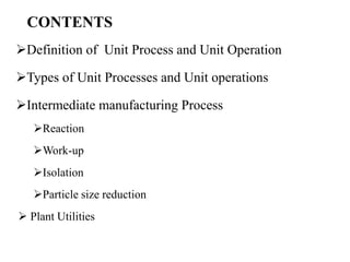
1. CONTENTS
Definition of Unit Process and Unit Operation
Types of Unit Processes and Unit operations
Intermediate manufacturing Process
Reaction
Work-up
Isolation
Particle size reduction
Plant Utilities
2. UNIT PROCESS
• Processes that involve making chemical changes to materials, as a
result of chemical reaction taking place.
• Unit processes are also referred to as chemical conversions.
Eg: Combustion, esterification, hydrogenation (Reduction) etc.
UNIT PROCESS
BATCH PROCESS CONTINOUS PROCESS
5. BATCH VS CONTINOUS PROCESS
Time taken for conversion of
reactants to products in Batch
process
Instantaneous reaction raw material
feeding and the product collection will be
donesimultaneously
6. Batch (vs.) continuous process
Batch process Continuous process
Material usage All types of material can be used in the
process i.e. flow able and non flow able
Easier for use with flowing materials
Installation size Relatively large installations Relatively small installations.
Reactor Changes occur in the concentrations of
materials over time.
Changes occur in the concentrations of
materials instantaneously
Feeding raw materials Before the start of the reaction. Constant feeding during the entire
reaction process.
Control of reactor condition It is easier to control reaction conditions
(pH, pressure, temperature). Manual
control can also be done.
Automatic control must be used.
Control of reactor conditions is more
difficult.
Product(s) Products can be isolation after
completion of reaction
Continuous isolation of products at all
times during the reaction.
Trouble shooting Trouble shooting can be done very
easily ,since we will check the quality at
all stages
Trouble shooting is very difficult ,since
we will not check the quality at all
stages
Production volume Preferable when production of small
quantities
Preferable for large scale production.
Multipurpose products in the plant Preferable when the plant produces a
wide variety of materials
Preferable for a central and permanent
product.
Product development stage It can be used in initial stage of
development
It can be used after optimization of
product
7. Reactor classification based on MOC
Reactor
Hastelloy
(HSTR)
Glass
lined
(GLR)
Stainless
Steel
(SSR)
Used for uniform corrosion attack
Used for both acidic & base pH
Used for pH of the reaction
mass ( < 7 )
is acidic & cannot be used for
Cryogenic operations
Used for reaction mass pH
is basic to neutral ( > 7 ) &
Cryogenic operations
11. Once the purpose of agitation is finalized, then desired
flow pattern and flow regime would decide the type of
impeller.
Types of flow patterns:
• Axial Mixing
• Radial Mixing
• Tangential Mixing
FLOW PATTERN IN REACTOR
Agitator selection – Flow Pattern
12. AGITATOR – TYPES
Flow pattern Types of
Agitators
Usage Photos/image
Tangential Anchor Used to mix high viscous fluids
Gives Tangential flow
Radial Flat blade/
Pitch disc
Turbine
Gas liquid dispersion for small
vessel at low gas rates
its the only logical choice for use
with fast competitive chemical
reactions
Radial Paddle type Ideal for applications where shear is
the primary requirement, or where
agitation close to the bottom of the
tank is desired.
Moderate pumping volume, gas
dispersions, emulsifications, radial
flow.
13. AGITATOR TYPES
Flow
pattern
Types of
Agitators
Usage Photos/image
Radial flow Retreat curve
impeller
General/multiple purpose
mixing, high pumping
volume, low to medium
viscosity, low volume, radial
flow
Axial flow Pitch blade
Turbine
Turbine mixing impeller for
more aggressive blending,
Ideal for viscous mixtures and
for applications requiring a
combination of pumping and
shearing.
Axial flow Marine
propeller Moderate pumping action
Viscosity limit 5000 cP
14. AGITATOR – SPECIAL TYPES
Flow pattern Types of
Agitators
Usage Photos/image
Axial Ekato -Isojet Axial flow impeller with
maximum pumping
efficiency
Axial Chemineer BT-6 Highest gas dispersing
capability
High and low viscous fluids
for better mass transfer
Axial Chemineer HE-3
(Down pumper)
An extremely efficient
turbulent flow impeller for
blending, heat transfer and
solids suspension. Most
effective for Reynolds
numbers over 50.
15. BAFFLES IN REACTOR
• Most batch reactors use baffles.
• These may be fixed to the top dish (mostly in GLR) or mounted on the interior
of the side walls (in SSR)
16. BAFFLES
Baffles are stationary blades which break up flow caused by the rotating agitator
and it will avoid vortex and swirling formation in reactor
17. BAFFLES-ADVANTAGES & LIMITATIONS
Advantages:
• Baffles are typically introduced to prevent vortex formation and convert tangential
(rotational) flow into axial (vertical) flow
• Baffles are always used in turbulent flow systems
Limitations
• A gap between the baffles and the wall is introduced to prevent stagnation behind
the baffles and accumulation of material (e.g., solids) it will take time in cleaning
• Baffles produced efficient mixing it will affect the crystallization property of the
material ( form change happens due to abnormal crystal growth – baffles are not
required )
• The other disadvantage can be increase of power consumption in the larger
volumes.
18. HEATING & COOLING JACKET TYPES
JACKET TYPE USAGE PHOTOS
Single external
jacket
Conventional jacket, with no internal
components, is generally very inefficient for
heat transfer because the flow media has an
extremely low velocity resulting in a low heat
transfer coefficient
Half coil jacket or
limpet coil jacket
In half coil jacket type heating and cooling can
be supplied separately this will not have dead
pockets of condensate and will have better
heat transfer compare to Single external jacket
Internal coil
Controlled flow of cooling Utility is circulated
through internal coils of a reactor. Utility fluid
will absorb the heat from process.
19. HEATING & COOLING JACKET TYPES
JACKET TYPE USAGE PHOTOS
Spiral jacket Spirals welded on outer surface of the
main vessel for uniform circulation of
heating or cooling media like steam, oil,
water etc. And also provides extra
strength to the main vessel
Double Jacket In double jacket system it will be used to
apply heating medium and cooling
medium separately
20. Do’s and Don’t related to Jacket
• Do’s
• Select the correct type of
utility based on process
energy load
• Follow strictly operating
discipline. While changing
over utility in jacket,
ensure that no presence of
earlier utility
• Strictly adhere to achedule
of jacket maintenance.
Periodic de-scaling is must.
• Don’t
• During utility changeover,
do not open supply valve
of a utility unless return
valve of other utility is not
closed.
• Do not ignore process
warnings in the form of
longer heating/cooling
cycles.
21. Jacket maintenance …why?
• Jacket space corrosion : This phenomenon occurs when
glass-lined reactor jackets are neglected until fouling
problems arise. Iron oxide corrosion, the most common
form of jacket fouling, results in prolonged heating and
cooling times, a reduction in product quality, and
equipment deterioration
Iron oxide deposition inside limpet coil jacket
22. Measures to avoid fouling
• Related to Thermal fluids used in jacket:
1. Water should be treated to remove impurities and
should contain a corrosive inhibitor.
2. Brine used for cooling must be kept at a neutral pH (the
recommended brine concentrations should have a
specific gravity of 1.2 and a pH of 8.0 – 8.5). Sodium
dichromate should be added in small quantities.
3. Never use brine alternately with steam or hot water. This
can result in a highly corrosive condition.
4. Some coolants may decompose to acid component
when exposed to heat/steam, leading to corrosion of
both the vessel and jacket steel.
23. Measures to avoid fouling
Preventive maintenance:
The jacket drain should be opened at least once a week
during operation to clean out all accumulated deposits and
periodically “blown down” to remove sludge, to prevent
premature failure due to corrosion.
Cleaning
Never use acid for cleaning the fouled jacket.
Use pH neutral cleaning agent
Cleaned limpet coil jacket
24. UTILITIES FOR HEATING AND COOLING
• Jacketed vessel is a container that is designed for controlling the temperature of
its contents, by using a cooling or heating "jacket" around the vessel through
which a cooling or heating fluid is circulated
• Heating fluid & intended service temperature
1. Low Pressure Saturated Steam < 3.5 kg/cm2 100 to 1350C
2. High Pressure Saturated Steam 3.5 – 5 kg/cm2 135 - 180 0C
2. Hot water 40 to 90 0C
3. Therminol / Dowtherm (Single Fluid utility) 180 to 200 0C
• Cooling fluid & intended service temperature
1. Cooling tower water or RT water up to 35 0C
2. Chilled brine 5 to - 35 0C
3. Chilled Water 35 to 8 0C
4. Liquid nitrogen ( Dedicated Jacket) -50 to -100 0C
5. Therminol / Dowtherm (Single fluid utility) 0 to -160 0C
28. Types of seals
Seal prevents the contents of the reactor from escaping during
operation, which could cause harm to the environment, the
equipment itself, and any personnel in the vicinity.
Wet seals: Use a liquid barrier fluid to provide lubrication and contain
the contents of the reactor under pressure.
Dry seals: Seal faces made from special grades of carbons and have
been machined to extremely tight tolerances. Barrier fluid is replaced
by Nitrogen
High purity seals: Employs a “debris well” that hangs below the seal in
the vapor space of the reactor. and its purpose is to catch a high
percentage of the carbon particles before they fall into the reactor
contents.
29. Magnetic seals
1. This sealing system comprehensively
eliminates all possible leakage risks, by
incorporating non-contact magnetic
seals. The agitator shaft does not
puncture the Reactor Vessel.
2. These systems are suitable for
Reactors of up to 50000 liters capacity,
temperature up to 300° C, and for
pressure up to 100 Bars.
* Used in Hydrogenation Reactors
30. Mechanical Seals - issues
Q1: What are the symptoms of a mechanical seal that is not running
properly?
Ans: There are varying symptoms of failing mechanical seals based on
the seal type.
1. Dry seals:
• higher than normal nitrogen consumption is often an indicator of a
problem as is hissing or puffing sounds from the seal housing.
• Flowmeter is placed in-line and the indicator ball is above allowable
limits (1-2 SCFH per inch of shaft diameter) or if the indicator ball is
bouncing in the meter.
2. Wet seals:
• Any means that are losing liquid at an increased rate or have run
totally dry prove to be problematic.
31. Mechanical seals – operating
mistakes
Q2: What are the most common operating mistakes made
with mechanical seals?
Ans: The three most common operating errors of
mechanical seals (that will eventually cause seal failures)
are:
1. Setting the pressure in the seal housing at too high or too
low a pressure.
2. Drive problems which cause high run-out of the agitator
shaft due to drive problems.
3. Running the agitator with full speed when the liquid level
is at the blade level.
32. Mechanical seals - inspection
Q3: What can you do to avoid seal problems?
Ans: Close and careful monitoring of the seal is the best way
to get an early diagnosis of seal issues. By proactively
inspecting key elements one can take preventative measures
to keep the seal running efficiently for longer. The three
most important components to monitor are:
• The liquid level of the lubricator for a wet seal.
• The agitator shaft (check for presence of run-out).
34. Temperature Indicators
S.No Type of
Contact
Type of
Temperature
sensor
Usage Photos
1 Direct contact Top sensor It is more reliable and practical to use one
location over the other when monitoring
and controlling the temperature in a
chemical process
2 Direct contact Bottom sensor Used for measuring temperature at
minimum level volume .
If it is measure for slurry then temperature
won’t be correct
3 Non contact Infrared sensor Used for measuring temperature at utility
lines and transfer lines
35. • Pressure : A pressure
sensor usually acts as a
transducer; it generates a
signal as a function of the
pressure imposed.
Instruments on reactor
• Data of pressure vs time is essential in processes,
especially those are carried out under vacuum.
• For some reactions, inert gas such as Nitrogen is used to
blanket the system and maintain positive pressure in the
system
36. Instruments on reactor
• Flow: A flow sensor is a device for sensing the rate of fluid
flow. Typically a flow sensor is the sensing element used in
a flow meter, or flow logger, to record the flow of fluids.
• Orifice type
flow meter
• Venturi
meter
• Direct force
37. Flowmeter
• Principle: The Variable Area Flowmeter is an instrument for
measuring the flow of liquids and gases in pipelines. It includes
a vertical tube through which the fluid flows whose diameter
increases from the bottom to the top and a float which can
move vertically in the tube.
• Regular calibration of flowmeter is
necessary for accurate flow-rate
reading
38. pH meters
• Purpose: On completion of reaction, product needs to be isolated
from impurities. This also includes selective transfer of product
from one layer to another. Therefore pH is adjusted before layer
separation.
• Principle: When immersed into the process solution, the measuring
electrode produces an electrical signal proportional to the hydrogen ion
activity. The reference electrode provides a stable basis for comparison and
completes the circuit. These two electrodes constitute an electrolytic cell with
a millivolt output that is proportional to the pH of the solution.
39. LEVEL MEASUREMENT OF
REACTOR
• Level measurement of the reactor is critical and it will
have impact on distillation concentration ,crystallization
and which in turn will affect the quality of the product
Types of Level measurements followed in API
• DIP ROD METHOD
• LEVEL TRANSMITTER
• LOAD CELL
40. LEVEL TRANSMITTER
• There are two basic types of level radar
instruments:
• Guided-wave radar and
• Non-contact wave radar.
42. Advantages of Radar level
transmitter
• Advantages
•Used on difficult ‘hard-to-handle’ applications
•High accuracy
•Non-contact
•Can measure level through plastic tanks
•Used to monitor contents of boxes or other multi-media material
•Detect obstructions in chutes or presses
Disadvantages
•Very sensitive to build-up on sensor surface
•They are very expensive. Price increases with increasing accuracy.
43. LOAD CELL
• A load cell is a sensor or a transducer that converts
a load or force acting on it into an electronic signal.
• This electronic signal can be a voltage change,
current change or frequency change depending on
the type of load cell and circuitry used.
• There are many different kinds of load cells. We
offer resistive load cells and capacitive load cells.
48. Safety measures while working with
Reactor
• Ensure earthling to the reactor and motor.
• Do not operate the reactor more than its capacity. Max. occupancy
of reactor is 80% of its total volume.
• RPM of agitators should not increase more than the manufacturer
recommendations
• In order to prevent frictional sparks between the agitator’s shaft and
coupling bushes the worn out parts must be replaced.
• Temperature and pressure gauges of reactor must be calibrated
periodically.
49. • During the reaction, if manhole cover has to be opened, stop the
agitator and wait for some time and then only the cover of the man
hole should be opened with provision of local exhaust ventilation to
avoid chemical exposure.
• Reactor vent must be kept open and also ensure the same except
during the time when the reactor has to be operated under vacuum
or negative pressure.
• Provision of suitable flame arrestors for the reactor vents.
Safety measures while working with Reactor
51. • Definition – PRV is a general term, which includes safety valves, relief
valves and safety relief valves.
1. Safety valve - A pressure relief valve actuated by inlet static pressure
and characterized by rapid opening or pop action.
2. Relief valve - A pressure relief device actuated by inlet static pressure
having a gradual lift generally proportional to the increase in pressure
over opening pressure.
3. Safety relief valve - A pressure relief valve characterized by rapid
opening or pop action, or by opening in proportion to the increase in
pressure over the opening pressure, depending on the application, and
which may be used either for liquid or compressible fluid.
Pressure Relief Valve (PRV)
52. Pressure Relief Valve (PRV)
There are a number of reasons why the pressure in a vessel or system
can exceed a predetermined limit. The most common are:
• Blocked discharge
• Exposure to external fire, often referred to as “Fire Case”
• Thermal expansion
• Chemical reaction
• Heat exchanger tube rupture
• Cooling system failure
PRV operates only when there is overpressure in the reactor system. The
sole purpose is to prevent the damage associated with high pressure.
54. Variants in PRV based on Back
pressure
The bellows is designed to cover
the same area on the back of the
disc equal to the seat area hence
the back pressure will have no
effect on the set pressure.
PRV with bellows type or
balanced-bellows type is used
when the back pressure up to
50% of set pressure
56. Advantages of Rupture Disks Used
in Combinations with Relief Valves
• Zero process leakage to the atmosphere;
• Longer periods between major
overhauls;
• Valves can be checked in place;
• Less expensive valve trim material can
be used;
• Valve life is extended by isolating
corrosive fluids from internal valve
parts.
57. DIP LEG/DIP PIPE
• Dip pipes provide
contained feeding of
corrosive and hazardous
chemical either above the
surface or below the
surface to prevent static
discharge.
• Also, in case of adding
reagent into a region of
high turbulence, such as tip
of the agitator blade, dip
pipe is useful.
58. Extraction - Basics
Principle:
Liquid extraction is a mass
transfer operation in which a
liquid solution (the feed-F) is
contacted with an immiscible
or nearly immiscible liquid
(solvent-S) that exhibits
preferential affinity or
selectivity towards one or
more of the components in
the feed.
Extract (E): The solvent rich
solution containing the
desired extracted solute
(Mostly it may be organic
layer)
Raffinate (R): The residual
feed solution containing little
solute (Mostly it may be
aqueous layer).
Distribution co-efficient Ratio
of concentrations of a
solute in each solvent. This is
constant at given
temperature
59. Extraction - Steps
Typical liquid-liquid extraction operations utilize the differences
in the solubility's of the components of a liquid mixture.
The basic steps involved include:
1. Contacting the feed with the extraction solvent.
2. Separation of the resulting phases.
3. Removal/recovery of solvent from each phase.
60. Solvent Selection for
extraction
Selectivity : The ability of the solvent to pick up the desired
component in the feed as compared to other components. Good
selectivity towards solute and little or no miscibility with feed
solution.
Recoverability: The solvent should be easily recoverable for recycle.
Density: Must be different so that phases can be separated by
settling
Chemical Reactivity: Solvent should be inert and stable
Safety : Should be non toxic
Cost : Should be low
Environmental : it should be class -2 or 3 solvent
61. Operating Conditions affecting extraction
Temperature: can also be used as a variable to alter
selectivity. Elevated temperatures are sometimes used in order to
keep viscosity low and thereby minimizing mass-transfer resistance
pH :The pH becomes significant in metal and bio-extractions. pH is
maintained to improve distribution coefficient and minimize
degradation of product.
Agitation & Mixing is an important parameter in extraction processes
, where Axial and Radial circulation required (e.g. propeller and
Turbine )
62. Cross-current Extraction
Crosscurrent mode is mostly used in batch operation. Batch extractors
have traditionally been used in low capacity multi-product plants such as
are typical in the pharmaceutical and agrochemical industries.
The extraction equipment is usually an agitated tank that may also be
used for the reaction steps. In these tanks, solvent is first added to
the feed, the contents are mixed, settled and then separated.
63. Negative Impact of ignoring extraction…
Higher Cost of solvent
Lower yields
Higher batch cycle times
Excess energy for distillation of solvent
High volume solvent -> high equipment occupancy -> larger
recovery system -> Complexity
Overload of system
64. When Extraction is better option than distillation?
When large volumes of water must be removed to complete a
separation. The large energy required to distill out water .
When two or more liquids form a close boiling azeotrope, the
desired final concentration may not be possible via distillation.
When one or more of the components are considered thermally
sensitive or unstable, distillation may not be a feasible option.
65. Extraction: General plant problems & Recommendations
If any Emulsions formed during extraction :
a) Slow down filtration through celite/Hyflow bed
b) Increase the concentration of ionic species may
helpful (Addition of sodium chloride, sodium sulphate
or potassium carbonate).
c) providing neutralization or acidification.
d) Emulations may sometimes be broken by addition of
a few drops of alcohol or other suitable solvents.
e) Changing the Impeller type / RPM
f) Changing the temperature
If Aqueous and Organic layers color is same:
Use pH probe or conductivity for identifying both layers
66. If product is soluble in water:
The solubility of many organic substances in water considerably
decreases by the presence of dissolved inorganic salts (Sodium
chloride, calcium chloride, ammonium sulphate, etc) (Salting-out
effect to be used in combination with extraction).
Can be used derivitization method - Amine reacts with aldehyde
to make stable amine and can be extracted with suitable organic
solvent. (Reactive extraction).
Extraction: General plant problems & Recommendations
67. ISOLATION
Concentration
• Rising Film evaporator
• Falling film evaporator
• Agitated thin film evaporator
• Atmospheric Distillation
• Vacuum Distillation
• Vacuum
68. Distillation
Batch Mode
Batch distillation refers to the use of distillation in batches.
The mixture in the reactor is supplied with energy and the
temperature is raised till the Boiling point. The vapour is
then condensed and collected in the collection receiver.
API Manufacturing involves Batch Distillation.
Continuous Mode
Continuous distillation is an ongoing separation process in
which a liquid mixture of two or more miscible
components is continuously fed into the process and
physically separated into two or more products by
preferentially boiling the more volatile (i.e., lower boiling
point) components out of the mixture.
70. Types of Distillation : Batch Mode
Atmospheric Distillation :
Atmospheric distillation is carried out at atmospheric pressure. During the distillation the
vent of the reactor distillation system is open to atmosphere.
Vacuum distillation :
Distillation of a liquid under reduced pressure, enabling it to boil at a lower temperature
than normal. Vacuum distillation is a method of distillation whereby the pressure above
the liquid mixture to be distilled is reduced to less than its atmospheric pressure causing
evaporation of the most volatile liquid(s). This distillation method works on the principle
that boiling occurs when the vapour pressure of a liquid exceeds the ambient pressure.
Vacuum distillation is used with or without heating the mixture. The vent of the reactor
system will be in closed condition.
71. Vacuum system :
• Vacuum distillation is selected over Atmospheric distillation due to
its various advantages. It is applicable for Temperature sensitive
products with high rates of Distillation for reduced Batch Time.
• Boiling point of the solvent reduces with reduced Pressure. Different
types of Vacuum are applied for different application in the process.
• Low Vacuum
• High Vacuum
73. Types of Vacuum pumps :
• Positive Displacement Vacuum Pumps
The positive displacement vacuum pumps are used to create low vacuums. The examples of positive displacement
vacuum pumps are liquid ring vacuum pumps and roots blower which are highly used in various industries to create
vacuum in confined space.
• Momentum Transfer Vacuum Pumps
In the vacuum pump where gas molecules are accelerated from the vacuum side to the exhaust side is known as
momentum transfer pump. Generally called high vacuum which is much more effective than positive displacement.
• Entrapment Pumps
Entrapment pumps work using chemical reactions, are known to perform more effectively because they are usually
placed inside the space or container to be vacuumed. This type of vacuum pump uses cold temperatures to
condense gases to a solid or absorbed state. To create ultra high vacuum chambers, the entrapment pumps are
used along with positive displacement vacuum pumps and momentum transfer vacuum pumps.
All the above types of vacuum pumps are further classified into liquid ring vacuum pumps, single cone vacuum
pumps, close couple vacuum pumps, two stage vacuum pumps, chemical process pumps and twin lobe roots
blower.
74. Commonly used Vacuum pumps :
• Liquid-ring pump
A liquid-ring pump is a rotating positive-displacement pump.
The most common sealant is water, almost any liquid can be used. The
second most common is oil. Since oil has a very low vapour pressure,
oil-sealed liquid-ring vacuum pumps are typically air-cooled.
• Dry Vacuum Pump
Dry running vacuum pumps are used increasingly throughout industry
where there is a growing demand for uncontaminated vacuum, free
from oil or service liquid, a requirement for low operating pressures, a
flexibility required from batch processes, concern about storage and
disposal costs of service liquids and the pressure to minimise life-cycle
costs. Moreover sealed unit meets these demands, whilst maintaining
a simple, cost-effective solution.
75. PUMPS
Pumps are divided into two fundamental types based on the manner in which they
transmit energy to the pumped media, namely, kinetic displacement or positive
displacement.
• In kinetic displacement, a centrifugal force of the rotating element, called an impeller,
imparts kinetic energy to the fluid, moving the fluid from pump suction to the
discharge.
• On the other hand, positive displacement uses the reciprocating action of one or
several pistons, or a squeezing action of meshing gears, lobes, or other moving bodies,
to displace the media from one area into another
76.
77. Commonly used Transfer pumps :
Centrifugal Pumps
• Very high capacity and low head.
• Smooth non pulsating Flow
Reciprocating pump
• which includes the piston pump,
plunger pump and diaphragm pump.
• It is often used where a relatively small quantity
of liquid is to be handled and where delivery
pressure is quite large.
78. AOD Pump :
• Offer the ability to vary flow and discharge pressure with a
simple adjustment of the air supply
• Are able to run dry without damage to pump
• Are capable of pumping as slow as one gallon per minute
Screw pump :
• A screw pump is a positive-displacement (PD) pump that use
one or several screws to move fluids or solids along the screw(s)
axis. A single screw rotates in a cylindrical cavity, thereby moving
the material along the screw's spindle.
Drum Charging pump :
• Used to Transfer the Liquids from Drum
to Drum, Drum to receiver following
required safety measures.
79. Rising film evaporator
• A Rising Film Evaporator (RFE) is a
vertical shell and tube heat
exchanger with a vapor – liquid
separator mounted at the top.
• The liquid to be concentrated is fed
at the bottom of the heated tube
bundle. As the liquid feed receives
the heat, the vapors generated lift
the liquid upwards and push it on
the wall as a film.
• The velocities generated by the
vapor lift are quite high, giving good
thermal performance. The balance
liquid and vapor are separated in the
vapor- liquid separator.
80. RFE is used in cases….
• Where circulation pump not required, due to Thermosiphon
action due to boiling in vertical tubes
• When trace quantities of suspended particles in the feed are
tolerated
• Where reasonable vacuum is available
• When steam economy is critical (thus, multiple effect
arrangement)
81. Falling Film Evaporator
The liquid to be concentrated is fed at the top
of the heated tubes and distributed in such a
way that it flows down on the inside surface of
the tubes as a thin film, under the influence of
gravity.
As the film gets heated, the vapors generated
flow co-currently. The drag of vapors increases
the turbulence and improves heat transfer
performance. The balance liquid and vapor are
separated in the vapor- liquid separator
A: Product
B: Vapor
C: Concentrate
D: Heating Steam
E: Condensate
1: Head
2: Calandria
3: Calandria, Lower part
4: Mixing Channel
5: Vapor Separator
82. Why to use FFE?
Suitable for heat sensitive products
Gentle evaporation with a short residence time in the evaporator
Can operate under reasonable vacuum
Multiple effect arrangement provides steam economy
83. Agitated Thin Film Evaporator
• Mechanically assisted to create
a thin film on inside surface of
evaporator
• Heat transfer from jacket on
evaporator
• Film flows under gravity and
becomes concentrated
• Evaporated fluid leaves
through top
• Variation is to wipe the film if
gravity is not enough – i.e.
fouling is possible or liquid is
viscous
http://www.technica.net/en/water/pollutants.htm
84. Why ATFE is better choice..
• Residence time of a few seconds with a narrow spread, an
important feature for heat sensitive products
• Required evaporation is achieved in a single pass, avoiding
product recirculation and possible degradation
• Scale formation on the heat transfer surface is reduced due to
the intense agitation of the liquid film
• Excellent turn down capability
• Low product holdup, ideal for hazardous applications
• Operating pressure as low as 1 mbar and operating temperature
up to 400 0C
85. Crystallization
• Formation of solid particles within a homogeneous
phase by modifying the solubility of the
component of interest.
• The change in solubility is accomplished by:
1. Decreasing the temperature of the solution
2. Changing the composition of solvent by adding
a solvent in which the compound is insoluble
(anti solvent crystallization).
Cooling crystallization: Concentrated solution gradually cooled below saturation
temperature (50-60°C) to generate a supersaturated state. Yields well defined
micron-sized crystals.
Evaporative crystallization: Solute dissolves in solution when heated to a certain
temperature (75°C). Slowly cooled until crystals precipitate
86. Why crystallization is so important…
• Various conditions in the crystallization process is the main
reason responsible for the development of different
polymorphic forms. These conditions include:
1. Solvent effects (the packing of crystal may be different in
polar and nonpolar solvents)
2. The level of supersaturation from which material is
crystallised (in which generally the higher the
concentration above the solubility, the more likelihood of
metastable formation)
3. Temperature at which crystallisation is carried out
4. Geometry of covalent bonds (differences leading to
conformational polymorphism)
5. Change in stirring conditions
87. Polymorph
• Polymorphs are one type of solid form. Polymorphs are
crystalline materials that have the same chemical
composition but different molecular packing.
• Polymorphism is important in the development of
pharmaceutical ingredients. Many drugs receive
regulatory approval for only a single crystal form or
polymorph.
• Polymorphism in drugs can also have direct medical
implications. Medicine is often administered orally as a
crystalline solid and dissolution rates depend on the
exact crystal form of a polymorph
89. FILTRATION
Seperation of solids from fluids
Terms used in filtration
• Feed
• Filter media
• Filtrate
• Wet cake
Filtration working principle
• Filter due to Pressure difference
• Filter due to Centrifugal force
Driving force of filtration are
Gravity Vaccum
Pressure centrifugal force
99. DRIER
Objective:
Removal of water or any another solvent by evaporation from a solid, semi-solid or liquid from
the solid material ,Final production step before selling or packaging products
Purpose
•Avoid moisture which decrease the product or drug stability.
•Improve the good properties of a material, e.g. flowability, compressibility.
•Reduce the cost of transportation of large volume materials ( liquids)
•Make the material easy or more suitable for handling.
•Driers which are commonly used in API indusrty are
Tray drier Vaccum tray drier
Fluidised bed drier Rotary cone vaccum drier
Freezer drier Spray drier
101. TRAY DRIER
Advantages:
•Handling of material will be easy
•Product changeover can be done effectively by easy cleaning
•Maintenance activity will be done easily
•Cost is cheap compare to other driers
Disadvantages:
•Expensive to operate
•Great heat losses;
•Different qualities of dried products from same batch
103. VACCUM TRAY DRIERS
• ADVANTAGES
• 1. Handling of the materials is easy
• 2. It provides large heat transfer surface area.
• 3. Heat sensitive material can be dried
• DISADVANTAGES
• 1. Dryer is a batch type process .
• 2. Low efficiency.and more expensive.
• 3.Cleaning is very diffucult
• 4.Maintaenance is also difficult
107. FLUIDISED BED DRIER
Advantages:
• Efficient heat and mass transfer give high drying rates
• Temperature of a fluidized bed is uniform and can be controlled precisely
• Handling of material will be easy
• Cleaning for product change over will be easy
• High out put from a small floor space
Disadvantages :
• Many organic powders develops electrostatic charges during drying. To avoid this efficient electrical earthing of the
dryer is essential.
• Turbelence of the fluidsed state of granules may causes attrition of some materials resulting in the production of fines.
109. SPRAY DRIER
Advantages:
• Drying is very fast
• Heat senstitive material can be dried
• Products will have fine size
Disadvantages:
• Occupy more space
• Operating cost is more expensive
110. FREEZE DRYING
• Freeze drying is a process used to dry extremely heat – sensitive materials. It allows the
drying , without excessive damage, of proteins, blood products and even microorganisms,
which retain a small but significant viability.
• In this process the initial liquid solution or suspension is frozen, the pressure above the
frozen state is reduced and the water removed by sublimation.
• Thus a liquid –to-vapour transition takes place, but here three states of matter involved:
liquid to solid, then solid to vapour
112. PARTICLE SIZE REDUCTION
Mechanical operations involves Size reducing equipments like Pulverizer,
Ultra fine miller, Micronizer and size seperation equipments like Sifter
Consider feed input ranges for each Size reducting equipment
Pulverizer :
Pulverizers are used for Grinding different types of materials
Out put from the pulverizer can get up to 50 - 60 Microns
Ultra Fine Miller :
Out put from the UFM can get up to 15 - 10 Microns
Micronizer :
Operated at high Pressure conditions
Out put from the Micronizer can get up to < 10 Microns
Sifter :
Sifter is used to get Homogenity of the final material
116. Heat Echangers
• Condensers are heat exchangers that condense vapours coming out from process
• Most commonly shell and tube heat exchangers (single pass, multipass) are used
for the purpose.
• In case of space constraints. Spiral condensers are used
• Generally shell side vapours, and tube side fluid coolant used
(Colling tower water, Chilled brine, Chilled water)
• Two condensers in series is the typical arrangement for condensation
Why condensation is required in the API manufacturing process?
• To recover organic solvents used in the manufacturing process.
• To prevent emission of vapours to atmosphere
What is the function of Primary & Secondary?
• Primary condensers remove the sensible heat
from vapour and CT water is used for the same
• Secondary condensers tremove the latent heat
from vapour and Chilled brine / Chilled water is
used for the same.
120. Importance aspects related
to cooling tower
• Cooling tower (CT) water is critical utility for any plant.
• Efficiency of cooling tower and quality of CT water impacts time
cycles of cooling operations.
• Blowdown: Evaporation and drift losses increase concentration of
minerals, hence regular blowdown of appropriate quantity is
essential.
• Chemicals: Addition of chemicals such as biocide, anti-foam, scale
inhibitors to water prevents microbe growth.
• Decrease in CT water temperature results in reduced efficiency of
chiller.
127. PROCESS PROBLEMS
1. For controlling the highly exothermic reactions, if we use normal jacketted vessel
we cannot control the reactor temperature by any means. Even though, we maintain
high coolant flow-rates we may not achieve set temperature. How will you control
the temperature?
We use internal coil-type cooling system which increases the heat transfer area
and it will result in maximum decrease of reactor temperature.
2. In the case of Heterogeneous reactions involving two-three phases, for
completing the reaction in the given batch time turbulence is necessary for good
contact between reactants.
As we all know we use agitators to overcome this. But what do you do when the use
of agitators create the problem of Vortex formation?
Vortices leads to the stagnant regions in the vessel. We opt for baffles to avoid this
problem.
128. PROCESS PROBLEMS
3. In a Heat exchanger, why we pass cold fluid to shell side and hot fluid to tube
side?
It need not to be always colder fluid in the shell. Sometimes we put the less-
corrosive fluid in the shell, or the lower-pressure fluid in the shell, or the less-
fouling fluid in the shell. Usually, the tubes are easier to produce for a particular
metallurgy and pressure rating than the shell, so we want the fluid that is harder
to contain in the tubes. Hot fluids are often harder to contain, and have more risk
of depositing scale -- so we often put them in the tubes.
4. What are the differences between unit operation and unit process?
In unit operations the mass and concentration change takes place (between
entrance and exit points) by providing energy from an external source and no
chemical change takes place. Eg: distillation, evaporation, mixing, etc.
While in case of unit process, processing of reactant in the feed takes place i.e
reactants in feed get converted into products (by chemical reaction) with the help
of either energy supplied to the system or generated by the system.
129. PROCESS PROBLEMS
5. Why do crystalline particles have better filtration rate as compared with slimy/fine powder?
Generally the large the particle size, the higher the filtration rate in Kg/m2/h and the lower the cake moisture.
The slimes or extreme fines in a filter feed slurry affect filtration rates to a vastly greater extent A particularly
difficult slurry is one that contains relatively coarse particles and a number of very fine or slimy particles with
little or no intermediate size. Filter aids like diatomaceous earth, perlite, powdered coal, fiy-ash or paper pulp
may be added to the flurry to increase its filtration rate and cake porosity.
6. How will you improve the filtration rate?
By increasing the pressure drop across cake bed – By raising pressure or vacuum. The applied vacuum/pressure
creates the pressure differential which is the driving force for filtration and dewatering. High vacuums give
somewhat higher rates and lower moistures in all cases except for unusually incompressible cakes.
Viscosity of liquor and temperature - Viscosity is closely related to temperature. As temperature is increased,
viscosity is decreased resulting in a higher filter capacity and lower cake moisture. At the same time, increased
vapor pressure will help reduce moisture.
Filter medium – Permeability and porosity are prime qualities in cloth selection
Slurry pH - Since slurry pH and particle dispersion are closely related, changes in pH could be one of the most
effective methods to improve filterability, if the process can tolerate it.
130. PROCESS PROBLEMS
7. Why cannot we handle hydrogenation reaction in conventional batch reactors?
Rate of reaction in conventional batch reactor is slow as compared with gas induction type
vessel. Hydrogenator generates huge amount of Gas-Liquid interfacial area resulting in
fastest possible reaction time with comparatively lower catalyst loadings. Where as in
Conventional Agitated Vessels Interfacial area is very poor as the agitator is designed only
for stirring the mass. Extra catalyst quantity is required to improve sluggish rate of reaction.
8. Exothermic reactions are releasing huge amount of heat during reaction. This heat is
continuously removed by circulating sufficient cooling medium to the jacket. What all are
control measures to be adopted in case of cooling circulation system fails to bring the reaction
mass in safer mode?
• Stop the reactant addition immediately.
• Agitator shall be stopped.
• Quench with suitable pre cooled solvent.
• Start secondary cooling system if provided.
131. PROCESS PROBLEMS
10. How will you detect leakages in the vacuum systems?
The simplest method to find out the leak points in the system is pressure test. Check the
working pressure of the particular equipment and apply the pressure to the equipment.
Prepare some soap solution and spray over all the flange joints. If leak is there, bubbles shall
be observed. Replace the gasket and repeat activity till constant pressure attained in the
system.
11.Entire reaction mass charged in to the ANFD and during filtration material passage
observed WHAT SHOUD BE DONE.
Immediately close the ML collection valve and reduce the pressure inside the ANFD. If still
material passage observed collect the MLS in separate cleaned mobile vessels or anti static
container for reprocess. Unload the material and check the integrity of the mesh/ cloth.
Replace the cloth and proceed further. Hence it is advisable to check the mesh/cloth
integrity and fixing before staring the filtration. It is also preferable to charge the reaction
mass lot wise in ANFD instead of charging entire reaction mass at a time.
132. PROCESS PROBLEMS
12. What all are the precautions to be taken to handle the low MIE/OEL value chemicals?
• Adopt closed material handling systems. (Glove Box, Isolators, powder transferring
system (PTS) and intermediate bulk containers (IBC))
• Ensure proper earthling.
• Maintain minimum time duration during charging the materials
• Ensure continuous inertization during material charging
13. During break down of the existing reactor, what are all the parameters need to be checked
for transferring reaction mass from existing reactor to new reactor?
• Material of construction (MOC)
• Minimum stirring volume
• Minimum sensing volume.
• Occupancy.
• Agitator type
133. PROCESS PROBLEMS
14. Why spray dryer is preferred over conventional dryers for drying heat sensitive materials?
• The surface area produced by atomization of the liquid feed enables a short gas residence
time, ranging from 3-40 seconds depending upon the application, which permits spray
drying without thermal degradation.
15. Why air leakages needs to arrest in distillation setup during vacuum distillation and how
will improve the solvent recovery %?
• Leakage in the system during vacuum distillation will affect the dew point temperature of
the solvent .If dew point temperature of the solvent is low we need to provide utility less
than the dew point temperature to collect the distilled solvents
16. Why dip pipe is required in the reactor for charging the solvents?
• To avoid and minimize the static dissipation
134. PROCESS PROBLEMS
17. How the performance of the Scrubber can be measured?
• Draft in the scrubber should be maintained as per design and it can be measured with
Manometer mm/wc.
18. What are all the steps to be followed before starting vacuum drying?
• 1. Vacuum trap to be emptied.
• 2. Vacuum pump should be started and check whether designed vacuum is achieved in
shut off condition
• 3. Ensure that ΔP across the inlet and outlet of the condenser is NMT 0.3 kg/cm2.
• 4. Ensure that the utility circulation to the condenser and the vacuum trap is continuous
and if required release air lock.
• 5. Leakage test to be carried out in drier is NMT 10 mm/wc.
135. PROCESS PROBLEMS
19. In ANFD operations, prior to drying operation, why is it important to ensure that cake has no cracks? What
are the control measures?
Ans: in ANFD, when majority of the filtrate passes through the filter, it indicates the completion of the
filtration operation. Prolonged squeezing of the wet cake to expel the filtrate causes development of cracks.
The next operation in the sequence is drying of wet cake. If cracks are not sealed before start of drying, then
Nitrogen or vacuum used for drying would by-pass through cracks. This will result in trapping of residual
solvent and consequent high loss on drying (LOD).
To avoid the above situation, before start of drying it is important to ensure that wet cake has no cracks. If
cracks are observed, then those should be sealed by systematic smoothing of cake by lowering agitator blades.
This can be easier to do BEFORE drying than during drying operation.
20. What is the need of Blowdown from cooling tower? How it can affect cooling time in process?
Ans: Evaporation of water from cooling tower results in the concentration of minerals present in the water.
The minerals content above a certain level will form hard scales and deposition throughout the system. Thus,
flushing a portion of high mineral concentration down the drain is required. This process is called Blow down.
There is a need to make up for drained quantity by using fresh water.
Scale deposition, in the absence of blow down, can restrict the flow of cooling water to the reactor jacket. In
addition, scale formation can take place in the supply header as well as reactor jacket itself. All these
probabilities will result in lesser supply of water than required to handle process heat load. This can result in
longer time to for cooling during the process.
136. PROCESS PROBLEMS
21. What is the purpose of having 2 condensers in series for most of the reactors in which distillation operation is carried
out?
• Ans: As the products & solvent handled in the reactors change, the heat transfer requirements for condensation
also change. It is not possible to provide the exact area based on respective solvent. Hence instead of one giant
condenser, practice of using two condensers is common to have flexibility.
• In general vapours from reactor contain non-condensable component which has tendency to carry condensable
solvent vapours along with it. Therefore, primary condenser having higher heat transfer area is used to condense
majority of vapour, using cooling tower water. The vapours escaping from vent of primary condenser are condensed
in secondary, using chilled brine or chilled water as utility.
22. In Which case the use of tray dryer is restricted?
• Ans: In API manufacturing, the use of try dryer is most common for drying the material. However, in case where
material has tendency to form lumps, use of tray dryer is restricted. In tray dryer, the air gets heated using
steam/hot water and is circulated in direct contact with the material. In cases where the material is sensitive to
direct contact with air, Roto cone vacuum dryer instead of tray dryer is used. In case of RCVD, direct contact
between heating media and material is avoided.
23. Sticking of mass to the walls of the reactor during Distillation?
• Ans: During Distillation it is commonly observed that the mass is thrown to the walls of the reactor due to the
action of agitator. The mass remains sticked to the walls of reactor due to poor heat transfer in the jacket of reactor.