SlideShare a Scribd company logo
1 of 118
Download to read offline
11-1
Section 11
Heat-Transfer Equipment
Richard L. Shilling, P.E., B.S.M., B.E.M.E., Manager of Engineering Development,
Brown Fintube Company—a Koch Engineering Company; Member, American Society of
Mechanical Engineers. (Shell-and-Tube Heat Exchangers, Hairpin/Double Pipe Heat Exchang-
ers, Air Cooled Heat Exchangers, Heating and Cooling of Tanks, Fouling and Scaling, Heat
Exchangers for Solids—significant contribution by Arthur D. Holt, Thermal Insulation—signif-
icant contribution by Herbert A. Moak) (Section Editor)
Kenneth J. Bell, Ph.D., P.E., Regents Professor Emeritus, School of Chemical Engineer-
ing, Oklahoma State University; Member, American Institute of Chemical Engineers. (Thermal
Design of Heat Exchangers, Condenser, Reboilers)
Patrick M. Bernhagen, P.E., B.S.M.E., Senior Mechanical Engineer, Foster Wheeler
USA Corporation, American Society of Mechanical Engineers. (Compact and Non-Tubular Heat
Exchangers)
Thomas M. Flynn, Ph.D., P.E., Cryogenic Engineer, President CRYOCO, Louisville,
Colorado; Member, American Institute of Chemical Engineers. (Cryogenic Processes)
Victor M. Goldschmidt, Ph.D., P.E., Professor of Mechanical Engineering, Purdue Uni-
versity, West Lafayette, Indiana. (Air Conditioning)
Predrag S. Hrnjak, Ph.D., V.Res., Assistant Professor, University of Illinois at Ubana
Champaign and Principal Investigator—U of I Air Conditioning and Refrigeration Center,
Assistant Professor, University of Belgrade; Member, International Institute of Refrigeration,
American Society of Heating, Refrigeration and Air Conditioning. (Refrigeration)
F. C. Standiford, M.S., P.E., Member, American Institute of Chemical Engineers, Ameri-
can Chemical Society. (Thermal Design of Evaporators, Evaporators)
Klaus D. Timmerhaus, Ph.D., P.E., Professor and President’s Teaching Scholar, Uni-
versity of Colorado, Boulder, Colorado; Fellow, American Institute of Chemical Engineers,
American Society for Engineering Education, American Association for the Advancement of Sci-
ence, Member, American Astronautical Society, National Academy of Engineering, Austrian
Academy of Science, International Institute of Refrigeration, American Society of Heating,
Refrigerating and Air Conditioning Engineers, American Society of Environmental Engineers,
Engineering Society for Advancing Mobility on Land, Sea, Air, and Space, Sigma Xi, The
Research Society. (Cryogenic Processes)
Copyright © 1999 by The McGraw-Hill Companies, Inc. All rights reserved. Use of
this product is subject to the terms of its license agreement. Click here to view.
THERMAL DESIGN OF HEAT-TRANSFER EQUIPMENT
Introduction to Thermal Design . . . . . . . . . . . . . . . . . . . . . . . . . . . . . . . 11-4
Approach to Heat-Exchanger Design . . . . . . . . . . . . . . . . . . . . . . . . . 11-4
Overall Heat-Transfer Coefficient . . . . . . . . . . . . . . . . . . . . . . . . . . . . 11-4
Mean Temperature Difference . . . . . . . . . . . . . . . . . . . . . . . . . . . . . . 11-4
Countercurrent or Cocurrent Flow . . . . . . . . . . . . . . . . . . . . . . . . . . . 11-4
Reversed, Mixed, or Cross-Flow . . . . . . . . . . . . . . . . . . . . . . . . . . . . . 11-5
Thermal Design for Single-Phase Heat Transfer . . . . . . . . . . . . . . . . . . 11-5
Double-Pipe Heat Exchangers . . . . . . . . . . . . . . . . . . . . . . . . . . . . . . 11-5
Baffled Shell-and-Tube Exchangers . . . . . . . . . . . . . . . . . . . . . . . . . . 11-7
Thermal Design of Condensers . . . . . . . . . . . . . . . . . . . . . . . . . . . . . . . . 11-11
Single-Component Condenser. . . . . . . . . . . . . . . . . . . . . . . . . . . . . . . 11-11
Multicomponent Condensers. . . . . . . . . . . . . . . . . . . . . . . . . . . . . . . . 11-12
Thermal Design of Reboilers . . . . . . . . . . . . . . . . . . . . . . . . . . . . . . . . . . 11-13
Kettle Reboilers . . . . . . . . . . . . . . . . . . . . . . . . . . . . . . . . . . . . . . . . . . 11-13
Vertical Thermosiphon Reboilers . . . . . . . . . . . . . . . . . . . . . . . . . . . . 11-13
Forced-Recirculation Reboilers. . . . . . . . . . . . . . . . . . . . . . . . . . . . . . 11-13
Thermal Design of Evaporators. . . . . . . . . . . . . . . . . . . . . . . . . . . . . . . . 11-13
Forced-Circulation Evaporators . . . . . . . . . . . . . . . . . . . . . . . . . . . . . 11-13
Long-Tube Vertical Evaporators . . . . . . . . . . . . . . . . . . . . . . . . . . . . . 11-14
Short-Tube Vertical Evaporators . . . . . . . . . . . . . . . . . . . . . . . . . . . . . 11-15
Miscellaneous Evaporator Types . . . . . . . . . . . . . . . . . . . . . . . . . . . . . 11-15
Heat Transfer from Various Metal Surfaces . . . . . . . . . . . . . . . . . . . . 11-16
Effect of Fluid Properties on Heat Transfer . . . . . . . . . . . . . . . . . . . . 11-17
Effect of Noncondensables on Heat Transfer . . . . . . . . . . . . . . . . . . . 11-18
Batch Operations: Heating and Cooling of Vessels. . . . . . . . . . . . . . . . . 11-18
Nomenclature . . . . . . . . . . . . . . . . . . . . . . . . . . . . . . . . . . . . . . . . . . . . 11-18
Applications. . . . . . . . . . . . . . . . . . . . . . . . . . . . . . . . . . . . . . . . . . . . . . 11-18
Effect of External Heat Loss or Gain . . . . . . . . . . . . . . . . . . . . . . . . . 11-19
Internal Coil or Jacket Plus External Heat Exchange. . . . . . . . . . . . . 11-19
Equivalent-Area Concept. . . . . . . . . . . . . . . . . . . . . . . . . . . . . . . . . . . 11-19
Nonagitated Batches. . . . . . . . . . . . . . . . . . . . . . . . . . . . . . . . . . . . . . . 11-19
Storage Tanks . . . . . . . . . . . . . . . . . . . . . . . . . . . . . . . . . . . . . . . . . . . . 11-19
Thermal Design of Tank Coils . . . . . . . . . . . . . . . . . . . . . . . . . . . . . . . . . 11-20
Nomenclature . . . . . . . . . . . . . . . . . . . . . . . . . . . . . . . . . . . . . . . . . . . . 11-20
Maintenance of Temperature. . . . . . . . . . . . . . . . . . . . . . . . . . . . . . . . 11-20
Heating . . . . . . . . . . . . . . . . . . . . . . . . . . . . . . . . . . . . . . . . . . . . . . . . . 11-20
Heating and Cooling of Tanks . . . . . . . . . . . . . . . . . . . . . . . . . . . . . . . . . 11-20
Tank Coils . . . . . . . . . . . . . . . . . . . . . . . . . . . . . . . . . . . . . . . . . . . . . . . 11-20
Teflon Immersion Coils . . . . . . . . . . . . . . . . . . . . . . . . . . . . . . . . . . . . 11-21
Bayonet Heaters . . . . . . . . . . . . . . . . . . . . . . . . . . . . . . . . . . . . . . . . . . 11-22
External Coils and Tracers . . . . . . . . . . . . . . . . . . . . . . . . . . . . . . . . . . 11-22
Jacketed Vessels . . . . . . . . . . . . . . . . . . . . . . . . . . . . . . . . . . . . . . . . . . 11-22
Extended or Finned Surfaces. . . . . . . . . . . . . . . . . . . . . . . . . . . . . . . . . . 11-22
Finned-Surface Application . . . . . . . . . . . . . . . . . . . . . . . . . . . . . . . . . 11-22
High Fins . . . . . . . . . . . . . . . . . . . . . . . . . . . . . . . . . . . . . . . . . . . . . . . 11-22
Low Fins . . . . . . . . . . . . . . . . . . . . . . . . . . . . . . . . . . . . . . . . . . . . . . . . 11-23
Fouling and Scaling . . . . . . . . . . . . . . . . . . . . . . . . . . . . . . . . . . . . . . . . . 11-23
Control of Fouling . . . . . . . . . . . . . . . . . . . . . . . . . . . . . . . . . . . . . . . . 11-23
Fouling Transients and Operating Periods . . . . . . . . . . . . . . . . . . . . . 11-23
Removal of Fouling Deposits. . . . . . . . . . . . . . . . . . . . . . . . . . . . . . . . 11-24
Fouling Resistances . . . . . . . . . . . . . . . . . . . . . . . . . . . . . . . . . . . . . . . 11-24
Typical Heat-Transfer Coefficients . . . . . . . . . . . . . . . . . . . . . . . . . . . . . 11-24
Thermal Design for Solids Processing. . . . . . . . . . . . . . . . . . . . . . . . . . . 11-24
Conductive Heat Transfer . . . . . . . . . . . . . . . . . . . . . . . . . . . . . . . . . . 11-24
Contactive (Direct) Heat Transfer. . . . . . . . . . . . . . . . . . . . . . . . . . . . 11-28
Convective Heat Transfer. . . . . . . . . . . . . . . . . . . . . . . . . . . . . . . . . . . 11-30
Radiative Heat Transfer . . . . . . . . . . . . . . . . . . . . . . . . . . . . . . . . . . . . 11-30
Scraped-Surface Exchangers . . . . . . . . . . . . . . . . . . . . . . . . . . . . . . . . . . 11-33
TEMA-STYLE SHELL-AND-TUBE HEAT EXCHANGERS
Types and Definitions. . . . . . . . . . . . . . . . . . . . . . . . . . . . . . . . . . . . . . . . 11-33
TEMA Numbering and Type Designations. . . . . . . . . . . . . . . . . . . . . 11-33
Functional Definitions . . . . . . . . . . . . . . . . . . . . . . . . . . . . . . . . . . . . . 11-33
General Design Considerations . . . . . . . . . . . . . . . . . . . . . . . . . . . . . . . . 11-35
Selection of Flow Path . . . . . . . . . . . . . . . . . . . . . . . . . . . . . . . . . . . . . 11-35
Construction Codes . . . . . . . . . . . . . . . . . . . . . . . . . . . . . . . . . . . . . . . 11-35
Tube Bundle Vibration . . . . . . . . . . . . . . . . . . . . . . . . . . . . . . . . . . . . . 11-35
Testing. . . . . . . . . . . . . . . . . . . . . . . . . . . . . . . . . . . . . . . . . . . . . . . . . . 11-35
Principal Types of Construction. . . . . . . . . . . . . . . . . . . . . . . . . . . . . . . . 11-36
Fixed-Tube-Sheet Heat Exchangers . . . . . . . . . . . . . . . . . . . . . . . . . . 11-36
U-Tube Heat Exchanger . . . . . . . . . . . . . . . . . . . . . . . . . . . . . . . . . . . 11-39
Packed-Lantern-Ring Exchanger. . . . . . . . . . . . . . . . . . . . . . . . . . . . . 11-39
Outside-Packed Floating-Head Exchanger. . . . . . . . . . . . . . . . . . . . . 11-39
Internal Floating-Head Exchanger . . . . . . . . . . . . . . . . . . . . . . . . . . . 11-40
Pull-Through Floating-Head Exchanger. . . . . . . . . . . . . . . . . . . . . . . 11-40
Falling-Film Exchangers . . . . . . . . . . . . . . . . . . . . . . . . . . . . . . . . . . . 11-40
Tube-Side Construction . . . . . . . . . . . . . . . . . . . . . . . . . . . . . . . . . . . . . . 11-40
Tube-Side Header. . . . . . . . . . . . . . . . . . . . . . . . . . . . . . . . . . . . . . . . . 11-40
Special High-Pressure Closures. . . . . . . . . . . . . . . . . . . . . . . . . . . . . . 11-40
Tube-Side Passes. . . . . . . . . . . . . . . . . . . . . . . . . . . . . . . . . . . . . . . . . . 11-40
Tubes . . . . . . . . . . . . . . . . . . . . . . . . . . . . . . . . . . . . . . . . . . . . . . . . . . . 11-40
Rolled Tube Joints . . . . . . . . . . . . . . . . . . . . . . . . . . . . . . . . . . . . . . . . 11-41
Welded Tube Joints . . . . . . . . . . . . . . . . . . . . . . . . . . . . . . . . . . . . . . . 11-41
Double-Tube-Sheet Joints . . . . . . . . . . . . . . . . . . . . . . . . . . . . . . . . . . 11-41
Shell-Side Construction . . . . . . . . . . . . . . . . . . . . . . . . . . . . . . . . . . . . . . 11-41
Shell Sizes . . . . . . . . . . . . . . . . . . . . . . . . . . . . . . . . . . . . . . . . . . . . . . . 11-41
Shell-Side Arrangements . . . . . . . . . . . . . . . . . . . . . . . . . . . . . . . . . . . 11-41
Baffles and Tube Bundles. . . . . . . . . . . . . . . . . . . . . . . . . . . . . . . . . . . . . 11-42
Segmental Baffles . . . . . . . . . . . . . . . . . . . . . . . . . . . . . . . . . . . . . . . . . 11-42
Rod Baffles . . . . . . . . . . . . . . . . . . . . . . . . . . . . . . . . . . . . . . . . . . . . . . 11-42
Tie Rods and Spacers . . . . . . . . . . . . . . . . . . . . . . . . . . . . . . . . . . . . . . 11-43
Impingement Baffle . . . . . . . . . . . . . . . . . . . . . . . . . . . . . . . . . . . . . . . 11-43
Vapor Distribution . . . . . . . . . . . . . . . . . . . . . . . . . . . . . . . . . . . . . . . . 11-43
Tube-Bundle Bypassing . . . . . . . . . . . . . . . . . . . . . . . . . . . . . . . . . . . . 11-43
Longitudinal Flow Baffles . . . . . . . . . . . . . . . . . . . . . . . . . . . . . . . . . . 11-43
Corrosion in Heat Exchangers . . . . . . . . . . . . . . . . . . . . . . . . . . . . . . . . . 11-43
Materials of Construction. . . . . . . . . . . . . . . . . . . . . . . . . . . . . . . . . . . 11-43
Bimetallic Tubes . . . . . . . . . . . . . . . . . . . . . . . . . . . . . . . . . . . . . . . . . . 11-43
Clad Tube Sheets . . . . . . . . . . . . . . . . . . . . . . . . . . . . . . . . . . . . . . . . . 11-44
Nonmetallic Construction . . . . . . . . . . . . . . . . . . . . . . . . . . . . . . . . . . 11-44
Fabrication . . . . . . . . . . . . . . . . . . . . . . . . . . . . . . . . . . . . . . . . . . . . . . 11-44
Shell-and-Tube Exchanger Costs. . . . . . . . . . . . . . . . . . . . . . . . . . . . . . . 11-44
HAIRPIN/DOUBLE-PIPE HEAT EXCHANGERS
Principles of Construction . . . . . . . . . . . . . . . . . . . . . . . . . . . . . . . . . . . . 11-46
Finned Double Pipes . . . . . . . . . . . . . . . . . . . . . . . . . . . . . . . . . . . . . . . . 11-46
Multitube Hairpins. . . . . . . . . . . . . . . . . . . . . . . . . . . . . . . . . . . . . . . . . . 11-46
Design Applications . . . . . . . . . . . . . . . . . . . . . . . . . . . . . . . . . . . . . . . . . 11-47
AIR-COOLED HEAT EXCHANGERS
Air Cooled Heat Exchangers . . . . . . . . . . . . . . . . . . . . . . . . . . . . . . . . . . 11-47
Forced and Induced Draft . . . . . . . . . . . . . . . . . . . . . . . . . . . . . . . . . . 11-47
Tube Bundle . . . . . . . . . . . . . . . . . . . . . . . . . . . . . . . . . . . . . . . . . . . . . 11-48
Tubing . . . . . . . . . . . . . . . . . . . . . . . . . . . . . . . . . . . . . . . . . . . . . . . . . . 11-48
Finned-Tube Construction. . . . . . . . . . . . . . . . . . . . . . . . . . . . . . . . . . 11-49
Fans. . . . . . . . . . . . . . . . . . . . . . . . . . . . . . . . . . . . . . . . . . . . . . . . . . . . 11-49
Fan Drivers . . . . . . . . . . . . . . . . . . . . . . . . . . . . . . . . . . . . . . . . . . . . . . 11-49
Fan Ring and Plenum Chambers. . . . . . . . . . . . . . . . . . . . . . . . . . . . . 11-50
Air-Flow Control. . . . . . . . . . . . . . . . . . . . . . . . . . . . . . . . . . . . . . . . . . 11-50
Air Recirculation. . . . . . . . . . . . . . . . . . . . . . . . . . . . . . . . . . . . . . . . . . 11-50
Trim Coolers . . . . . . . . . . . . . . . . . . . . . . . . . . . . . . . . . . . . . . . . . . . . . 11-50
Humidification Chambers . . . . . . . . . . . . . . . . . . . . . . . . . . . . . . . . . . 11-50
Evaporative Cooling . . . . . . . . . . . . . . . . . . . . . . . . . . . . . . . . . . . . . . . 11-50
Steam Condensers . . . . . . . . . . . . . . . . . . . . . . . . . . . . . . . . . . . . . . . . 11-51
Air-Cooled Overhead Condensers . . . . . . . . . . . . . . . . . . . . . . . . . . . . 11-51
Air-Cooled Heat-Exchanger Costs. . . . . . . . . . . . . . . . . . . . . . . . . . . . 11-51
Design Considerations . . . . . . . . . . . . . . . . . . . . . . . . . . . . . . . . . . . . . 11-51
COMPACT AND NONTUBULAR HEAT EXCHANGERS
Compact Heat Exchangers. . . . . . . . . . . . . . . . . . . . . . . . . . . . . . . . . . . . 11-52
Plate-and-Frame Exchangers. . . . . . . . . . . . . . . . . . . . . . . . . . . . . . . . . . 11-52
Gasketed-Plate Exchangers . . . . . . . . . . . . . . . . . . . . . . . . . . . . . . . . . . . 11-52
Description . . . . . . . . . . . . . . . . . . . . . . . . . . . . . . . . . . . . . . . . . . . . . . 11-52
Applications. . . . . . . . . . . . . . . . . . . . . . . . . . . . . . . . . . . . . . . . . . . . . . 11-52
Design . . . . . . . . . . . . . . . . . . . . . . . . . . . . . . . . . . . . . . . . . . . . . . . . . . 11-53
Welded- and Brazed-Plate Exchangers . . . . . . . . . . . . . . . . . . . . . . . . . . 11-55
Spiral-Plate Exchangers . . . . . . . . . . . . . . . . . . . . . . . . . . . . . . . . . . . . . . 11-55
Description . . . . . . . . . . . . . . . . . . . . . . . . . . . . . . . . . . . . . . . . . . . . . . 11-55
Applications. . . . . . . . . . . . . . . . . . . . . . . . . . . . . . . . . . . . . . . . . . . . . . 11-55
Design . . . . . . . . . . . . . . . . . . . . . . . . . . . . . . . . . . . . . . . . . . . . . . . . . . 11-55
Brazed-Plate-Fin Exchangers . . . . . . . . . . . . . . . . . . . . . . . . . . . . . . . . . 11-56
Plate-Fin Tubular Exchangers (PFE) . . . . . . . . . . . . . . . . . . . . . . . . . . . 11-56
Description . . . . . . . . . . . . . . . . . . . . . . . . . . . . . . . . . . . . . . . . . . . . . . 11-56
Applications. . . . . . . . . . . . . . . . . . . . . . . . . . . . . . . . . . . . . . . . . . . . . . 11-56
Design . . . . . . . . . . . . . . . . . . . . . . . . . . . . . . . . . . . . . . . . . . . . . . . . . . 11-56
Spiral-Tube Exchangers (STE) . . . . . . . . . . . . . . . . . . . . . . . . . . . . . . . . 11-56
Description . . . . . . . . . . . . . . . . . . . . . . . . . . . . . . . . . . . . . . . . . . . . . . 11-56
Applications. . . . . . . . . . . . . . . . . . . . . . . . . . . . . . . . . . . . . . . . . . . . . . 11-56
Design . . . . . . . . . . . . . . . . . . . . . . . . . . . . . . . . . . . . . . . . . . . . . . . . . . 11-56
Graphite Heat Exchangers. . . . . . . . . . . . . . . . . . . . . . . . . . . . . . . . . . . . 11-57
Description . . . . . . . . . . . . . . . . . . . . . . . . . . . . . . . . . . . . . . . . . . . . . . 11-57
Applications and Design. . . . . . . . . . . . . . . . . . . . . . . . . . . . . . . . . . . . 11-57
Cascade Coolers . . . . . . . . . . . . . . . . . . . . . . . . . . . . . . . . . . . . . . . . . . . . 11-57
Bayonet-Tube Exchangers . . . . . . . . . . . . . . . . . . . . . . . . . . . . . . . . . . . . 11-57
Atmospheric Sections . . . . . . . . . . . . . . . . . . . . . . . . . . . . . . . . . . . . . . . . 11-57
Nonmetallic Heat Exchangers . . . . . . . . . . . . . . . . . . . . . . . . . . . . . . . . . 11-57
PVDF Heat Exchangers. . . . . . . . . . . . . . . . . . . . . . . . . . . . . . . . . . . . . . 11-57
Ceramic Heat Exchangers . . . . . . . . . . . . . . . . . . . . . . . . . . . . . . . . . . . . 11-58
Teflon Heat Exchangers . . . . . . . . . . . . . . . . . . . . . . . . . . . . . . . . . . . . . . 11-58
11-2 HEAT-TRANSFER EQUIPMENT
Copyright © 1999 by The McGraw-Hill Companies, Inc. All rights reserved. Use of
this product is subject to the terms of its license agreement. Click here to view.
HEAT EXCHANGERS FOR SOLIDS
Equipment for Solidification . . . . . . . . . . . . . . . . . . . . . . . . . . . . . . . . . . 11-58
Table Type. . . . . . . . . . . . . . . . . . . . . . . . . . . . . . . . . . . . . . . . . . . . . . . 11-58
Agitated-Pan Type . . . . . . . . . . . . . . . . . . . . . . . . . . . . . . . . . . . . . . . . 11-58
Vibratory Type. . . . . . . . . . . . . . . . . . . . . . . . . . . . . . . . . . . . . . . . . . . . 11-59
Belt Types . . . . . . . . . . . . . . . . . . . . . . . . . . . . . . . . . . . . . . . . . . . . . . . 11-59
Rotating-Drum Type . . . . . . . . . . . . . . . . . . . . . . . . . . . . . . . . . . . . . . 11-60
Rotating-Shelf Type . . . . . . . . . . . . . . . . . . . . . . . . . . . . . . . . . . . . . . . 11-61
Equipment for Fusion of Solids. . . . . . . . . . . . . . . . . . . . . . . . . . . . . . . . 11-61
Horizontal-Tank Type. . . . . . . . . . . . . . . . . . . . . . . . . . . . . . . . . . . . . . 11-61
Vertical Agitated-Kettle Type. . . . . . . . . . . . . . . . . . . . . . . . . . . . . . . . 11-61
Mill Type . . . . . . . . . . . . . . . . . . . . . . . . . . . . . . . . . . . . . . . . . . . . . . . . 11-61
Heat-Transfer Equipment for Sheeted Solids. . . . . . . . . . . . . . . . . . . . . 11-62
Cylinder Heat-Transfer Units . . . . . . . . . . . . . . . . . . . . . . . . . . . . . . . 11-62
Heat-Transfer Equipment for Divided Solids. . . . . . . . . . . . . . . . . . . . . 11-62
Fluidized-Bed Type . . . . . . . . . . . . . . . . . . . . . . . . . . . . . . . . . . . . . . . 11-62
Moving-Bed Type . . . . . . . . . . . . . . . . . . . . . . . . . . . . . . . . . . . . . . . . . 11-63
Agitated-Pan Type . . . . . . . . . . . . . . . . . . . . . . . . . . . . . . . . . . . . . . . . 11-63
Kneading Devices. . . . . . . . . . . . . . . . . . . . . . . . . . . . . . . . . . . . . . . . . 11-63
Shelf Devices . . . . . . . . . . . . . . . . . . . . . . . . . . . . . . . . . . . . . . . . . . . . 11-63
Rotating-Shell Devices . . . . . . . . . . . . . . . . . . . . . . . . . . . . . . . . . . . . . 11-63
Conveyor-Belt Devices. . . . . . . . . . . . . . . . . . . . . . . . . . . . . . . . . . . . . 11-64
Spiral-Conveyor Devices . . . . . . . . . . . . . . . . . . . . . . . . . . . . . . . . . . . 11-64
Double-Cone Blending Devices . . . . . . . . . . . . . . . . . . . . . . . . . . . . . 11-65
Vibratory-Conveyor Devices . . . . . . . . . . . . . . . . . . . . . . . . . . . . . . . . 11-65
Elevator Devices. . . . . . . . . . . . . . . . . . . . . . . . . . . . . . . . . . . . . . . . . . 11-67
Pneumatic-Conveying Devices . . . . . . . . . . . . . . . . . . . . . . . . . . . . . . 11-67
Vacuum-Shelf Types . . . . . . . . . . . . . . . . . . . . . . . . . . . . . . . . . . . . . . . 11-67
THERMAL INSULATION
Insulation Materials . . . . . . . . . . . . . . . . . . . . . . . . . . . . . . . . . . . . . . . . . 11-68
Materials . . . . . . . . . . . . . . . . . . . . . . . . . . . . . . . . . . . . . . . . . . . . . . . . 11-68
Thermal Conductivity (K Factor). . . . . . . . . . . . . . . . . . . . . . . . . . . . . 11-68
Finishes . . . . . . . . . . . . . . . . . . . . . . . . . . . . . . . . . . . . . . . . . . . . . . . . . 11-68
System Selection. . . . . . . . . . . . . . . . . . . . . . . . . . . . . . . . . . . . . . . . . . . . 11-69
Cryogenic High Vacuum . . . . . . . . . . . . . . . . . . . . . . . . . . . . . . . . . . . 11-69
Low Temperature . . . . . . . . . . . . . . . . . . . . . . . . . . . . . . . . . . . . . . . . . 11-69
Moderate and High Temperature . . . . . . . . . . . . . . . . . . . . . . . . . . . . 11-69
Economic Thickness of Insulation. . . . . . . . . . . . . . . . . . . . . . . . . . . . . . 11-70
Recommended Thickness of Insulation. . . . . . . . . . . . . . . . . . . . . . . . 11-70
Example 1 . . . . . . . . . . . . . . . . . . . . . . . . . . . . . . . . . . . . . . . . . . . . . . . 11-73
Example 2 . . . . . . . . . . . . . . . . . . . . . . . . . . . . . . . . . . . . . . . . . . . . . . . 11-73
Example 3 . . . . . . . . . . . . . . . . . . . . . . . . . . . . . . . . . . . . . . . . . . . . . . . 11-73
Installation Practice . . . . . . . . . . . . . . . . . . . . . . . . . . . . . . . . . . . . . . . . . 11-73
Pipe . . . . . . . . . . . . . . . . . . . . . . . . . . . . . . . . . . . . . . . . . . . . . . . . . . . . 11-73
Method of Securing . . . . . . . . . . . . . . . . . . . . . . . . . . . . . . . . . . . . . . . 11-73
Double Layer . . . . . . . . . . . . . . . . . . . . . . . . . . . . . . . . . . . . . . . . . . . . 11-73
Finish. . . . . . . . . . . . . . . . . . . . . . . . . . . . . . . . . . . . . . . . . . . . . . . . . . . 11-73
Tanks, Vessels, and Equipment . . . . . . . . . . . . . . . . . . . . . . . . . . . . . . 11-73
Method of Securing . . . . . . . . . . . . . . . . . . . . . . . . . . . . . . . . . . . . . . . 11-73
Finish. . . . . . . . . . . . . . . . . . . . . . . . . . . . . . . . . . . . . . . . . . . . . . . . . . . 11-74
AIR CONDITIONING
Introduction . . . . . . . . . . . . . . . . . . . . . . . . . . . . . . . . . . . . . . . . . . . . . . . 11-74
Comfort Air Conditioning . . . . . . . . . . . . . . . . . . . . . . . . . . . . . . . . . . . . 11-74
Industrial Air Conditioning . . . . . . . . . . . . . . . . . . . . . . . . . . . . . . . . . . . 11-74
Ventilation . . . . . . . . . . . . . . . . . . . . . . . . . . . . . . . . . . . . . . . . . . . . . . . . . 11-74
Air-Conditioning Equipment . . . . . . . . . . . . . . . . . . . . . . . . . . . . . . . . . . 11-74
Central Systems . . . . . . . . . . . . . . . . . . . . . . . . . . . . . . . . . . . . . . . . . . . . 11-75
Unitary Refrigerant-Based Air-Conditioning Systems . . . . . . . . . . . . . . 11-75
Load Calculation. . . . . . . . . . . . . . . . . . . . . . . . . . . . . . . . . . . . . . . . . . . . 11-76
REFRIGERATION
Introduction . . . . . . . . . . . . . . . . . . . . . . . . . . . . . . . . . . . . . . . . . . . . . . . 11-76
Basic Principles. . . . . . . . . . . . . . . . . . . . . . . . . . . . . . . . . . . . . . . . . . . 11-76
Basic Refrigeration Methods . . . . . . . . . . . . . . . . . . . . . . . . . . . . . . . . 11-76
Mechanical Refrigeration (Vapor-Compression Systems) . . . . . . . . . . . 11-77
Vapor-Compression Cycles. . . . . . . . . . . . . . . . . . . . . . . . . . . . . . . . . . 11-77
Multistage Systems . . . . . . . . . . . . . . . . . . . . . . . . . . . . . . . . . . . . . . . . 11-78
Cascade System. . . . . . . . . . . . . . . . . . . . . . . . . . . . . . . . . . . . . . . . . . . 11-79
Equipment . . . . . . . . . . . . . . . . . . . . . . . . . . . . . . . . . . . . . . . . . . . . . . . . 11-79
Compressors . . . . . . . . . . . . . . . . . . . . . . . . . . . . . . . . . . . . . . . . . . . . . 11-79
Positive-Displacement Compressors . . . . . . . . . . . . . . . . . . . . . . . . . . 11-80
Centrifugal Compressors . . . . . . . . . . . . . . . . . . . . . . . . . . . . . . . . . . . 11-83
Condensers . . . . . . . . . . . . . . . . . . . . . . . . . . . . . . . . . . . . . . . . . . . . . . 11-83
Evaporators. . . . . . . . . . . . . . . . . . . . . . . . . . . . . . . . . . . . . . . . . . . . . . 11-84
System Analysis. . . . . . . . . . . . . . . . . . . . . . . . . . . . . . . . . . . . . . . . . . . 11-85
System, Equipment, and Refrigerant Selection . . . . . . . . . . . . . . . . . 11-87
Other Refrigerant Systems Applied in the Industry . . . . . . . . . . . . . . . . 11-88
Absorption Refrigeration Systems . . . . . . . . . . . . . . . . . . . . . . . . . . . . 11-88
Steam-Jet (Ejector) Systems . . . . . . . . . . . . . . . . . . . . . . . . . . . . . . . . 11-89
Multistage Systems . . . . . . . . . . . . . . . . . . . . . . . . . . . . . . . . . . . . . . . . 11-93
Capacity Control. . . . . . . . . . . . . . . . . . . . . . . . . . . . . . . . . . . . . . . . . . 11-93
Refrigerants. . . . . . . . . . . . . . . . . . . . . . . . . . . . . . . . . . . . . . . . . . . . . . 11-93
Secondary Refrigerants (Antifreezes or Brines) . . . . . . . . . . . . . . . . . 11-94
Organic Compounds (Inhibited Glycols). . . . . . . . . . . . . . . . . . . . . . . 11-95
Safety in Refrigeration Systems . . . . . . . . . . . . . . . . . . . . . . . . . . . . . . 11-96
CRYOGENIC PROCESSES
Introduction . . . . . . . . . . . . . . . . . . . . . . . . . . . . . . . . . . . . . . . . . . . . . . . 11-96
Properties of Cryogenic Fluids . . . . . . . . . . . . . . . . . . . . . . . . . . . . . . . . 11-96
Properties of Solids. . . . . . . . . . . . . . . . . . . . . . . . . . . . . . . . . . . . . . . . . . 11-96
Structural Properties at Low Temperatures . . . . . . . . . . . . . . . . . . . . 11-97
Thermal Properties at Low Temperatures . . . . . . . . . . . . . . . . . . . . . 11-97
Electrical Properties at Low Temperatures. . . . . . . . . . . . . . . . . . . . . 11-97
Superconductivity. . . . . . . . . . . . . . . . . . . . . . . . . . . . . . . . . . . . . . . . . 11-97
Refrigeration and Liquifaction. . . . . . . . . . . . . . . . . . . . . . . . . . . . . . . . . 11-98
Principles. . . . . . . . . . . . . . . . . . . . . . . . . . . . . . . . . . . . . . . . . . . . . . . . 11-98
Expansion Types of Refrigerators . . . . . . . . . . . . . . . . . . . . . . . . . . . . 11-98
Miniature Refrigerators . . . . . . . . . . . . . . . . . . . . . . . . . . . . . . . . . . . . 11-100
Thermodynamic Analyses of Cycles. . . . . . . . . . . . . . . . . . . . . . . . . . . 11-100
Process Equipment. . . . . . . . . . . . . . . . . . . . . . . . . . . . . . . . . . . . . . . . . . 11-100
Heat Exchangers. . . . . . . . . . . . . . . . . . . . . . . . . . . . . . . . . . . . . . . . . . 11-101
Expanders . . . . . . . . . . . . . . . . . . . . . . . . . . . . . . . . . . . . . . . . . . . . . . . 11-101
Separation and Purification Systems . . . . . . . . . . . . . . . . . . . . . . . . . . . . 11-102
Air-Separation Systems. . . . . . . . . . . . . . . . . . . . . . . . . . . . . . . . . . . . . 11-102
Helium and Natural-Gas Systems Separation . . . . . . . . . . . . . . . . . . . 11-103
Gas Purification . . . . . . . . . . . . . . . . . . . . . . . . . . . . . . . . . . . . . . . . . . 11-103
Storage and Transfer Systems . . . . . . . . . . . . . . . . . . . . . . . . . . . . . . . . . 11-104
Insulation Principles. . . . . . . . . . . . . . . . . . . . . . . . . . . . . . . . . . . . . . . 11-104
Types of Insulation . . . . . . . . . . . . . . . . . . . . . . . . . . . . . . . . . . . . . . . . 11-104
Storage and Transfer Systems . . . . . . . . . . . . . . . . . . . . . . . . . . . . . . . 11-105
Cryogenic Instrumentation . . . . . . . . . . . . . . . . . . . . . . . . . . . . . . . . . . . 11-106
Pressure. . . . . . . . . . . . . . . . . . . . . . . . . . . . . . . . . . . . . . . . . . . . . . . . . 11-106
Liquid Level . . . . . . . . . . . . . . . . . . . . . . . . . . . . . . . . . . . . . . . . . . . . . 11-106
Flow. . . . . . . . . . . . . . . . . . . . . . . . . . . . . . . . . . . . . . . . . . . . . . . . . . . . 11-106
Temperature . . . . . . . . . . . . . . . . . . . . . . . . . . . . . . . . . . . . . . . . . . . . . 11-106
Safety. . . . . . . . . . . . . . . . . . . . . . . . . . . . . . . . . . . . . . . . . . . . . . . . . . . . . 11-106
Physiological Hazards. . . . . . . . . . . . . . . . . . . . . . . . . . . . . . . . . . . . . . 11-107
Materials and Construction Hazards . . . . . . . . . . . . . . . . . . . . . . . . . . 11-107
Flammability and Explosion Hazards . . . . . . . . . . . . . . . . . . . . . . . . . 11-107
High-Pressure Gas Hazards . . . . . . . . . . . . . . . . . . . . . . . . . . . . . . . . . 11-107
Summary . . . . . . . . . . . . . . . . . . . . . . . . . . . . . . . . . . . . . . . . . . . . . . . . . . 11-107
EVAPORATORS
Primary Design Problems . . . . . . . . . . . . . . . . . . . . . . . . . . . . . . . . . . . . 11-107
Heat Transfer . . . . . . . . . . . . . . . . . . . . . . . . . . . . . . . . . . . . . . . . . . . . 11-107
Vapor-Liquid Separation . . . . . . . . . . . . . . . . . . . . . . . . . . . . . . . . . . . 11-107
Selection Problems . . . . . . . . . . . . . . . . . . . . . . . . . . . . . . . . . . . . . . . . 11-107
Product Quality. . . . . . . . . . . . . . . . . . . . . . . . . . . . . . . . . . . . . . . . . . . 11-108
Evaporator Types and Applications . . . . . . . . . . . . . . . . . . . . . . . . . . . . . 11-108
Forced-Circulation Evaporators . . . . . . . . . . . . . . . . . . . . . . . . . . . . . 11-108
Short-Tube Vertical Evaporators . . . . . . . . . . . . . . . . . . . . . . . . . . . . . 11-109
Long-Tube Vertical Evaporators . . . . . . . . . . . . . . . . . . . . . . . . . . . . . 11-109
Horizontal-Tube Evaporators. . . . . . . . . . . . . . . . . . . . . . . . . . . . . . . . 11-110
Miscellaneous Forms of Heating Surface . . . . . . . . . . . . . . . . . . . . . . 11-111
Evaporators without Heating Surfaces . . . . . . . . . . . . . . . . . . . . . . . . 11-111
Utilization of Temperature Difference . . . . . . . . . . . . . . . . . . . . . . . . . . 11-111
Vapor-Liquid Separation . . . . . . . . . . . . . . . . . . . . . . . . . . . . . . . . . . . . . 11-111
Evaporator Arrangement . . . . . . . . . . . . . . . . . . . . . . . . . . . . . . . . . . . . . 11-113
Single-Effect Evaporators . . . . . . . . . . . . . . . . . . . . . . . . . . . . . . . . . . 11-113
Thermocompression. . . . . . . . . . . . . . . . . . . . . . . . . . . . . . . . . . . . . . . 11-113
Multiple-Effect Evaporation . . . . . . . . . . . . . . . . . . . . . . . . . . . . . . . . 11-113
Seawater Evaporators. . . . . . . . . . . . . . . . . . . . . . . . . . . . . . . . . . . . . . 11-114
Evaporator Calculations . . . . . . . . . . . . . . . . . . . . . . . . . . . . . . . . . . . . . . 11-115
Single-Effect Evaporators . . . . . . . . . . . . . . . . . . . . . . . . . . . . . . . . . . 11-115
Thermocompression Evaporators . . . . . . . . . . . . . . . . . . . . . . . . . . . . 11-115
Flash Evaporators. . . . . . . . . . . . . . . . . . . . . . . . . . . . . . . . . . . . . . . . . 11-115
Multiple-Effect Evaporators . . . . . . . . . . . . . . . . . . . . . . . . . . . . . . . . 11-117
Optimization . . . . . . . . . . . . . . . . . . . . . . . . . . . . . . . . . . . . . . . . . . . . . 11-117
Evaporator Accessories. . . . . . . . . . . . . . . . . . . . . . . . . . . . . . . . . . . . . . . 11-117
Condensers . . . . . . . . . . . . . . . . . . . . . . . . . . . . . . . . . . . . . . . . . . . . . . 11-117
Vent Systems . . . . . . . . . . . . . . . . . . . . . . . . . . . . . . . . . . . . . . . . . . . . . 11-117
Salt Removal . . . . . . . . . . . . . . . . . . . . . . . . . . . . . . . . . . . . . . . . . . . . . 11-117
Evaporator Operation. . . . . . . . . . . . . . . . . . . . . . . . . . . . . . . . . . . . . . . . 11-118
HEAT-TRANSFER EQUIPMENT 11-3
Copyright © 1999 by The McGraw-Hill Companies, Inc. All rights reserved. Use of
this product is subject to the terms of its license agreement. Click here to view.
THERMAL DESIGN OF HEAT-TRANSFER EQUIPMENT
INTRODUCTION TO THERMAL DESIGN
Design methods for several important classes of process heat-transfer
equipment are presented in the following portions of Sec. 11.
Mechanical descriptions and specifications of equipment are given in
this section and should be read in conjunction with the use of this
material. It is impossible to present here a comprehensive treatment
of heat-exchanger selection, design, and application. The best general
references in this field are Hewitt, Shires, and Bott, Process Heat
Transfer, CRC Press, Boca Raton, FL, 1994; and Schlünder (ed.),
Heat Exchanger Design Handbook, Begell House, New York, 1983.
Approach to Heat-Exchanger Design The proper use of basic
heat-transfer knowledge in the design of practical heat-transfer equip-
ment is an art. Designers must be constantly aware of the differences
between the idealized conditions for and under which the basic
knowledge was obtained and the real conditions of the mechanical
expression of their design and its environment. The result must satisfy
process and operational requirements (such as availability, flexibility,
and maintainability) and do so economically. An important part of any
design process is to consider and offset the consequences of error in
the basic knowledge, in its subsequent incorporation into a design
method, in the translation of design into equipment, or in the opera-
tion of the equipment and the process. Heat-exchanger design is not a
highly accurate art under the best of conditions.
The design of a process heat exchanger usually proceeds through
the following steps:
1. Process conditions (stream compositions, flow rates, tempera-
tures, pressures) must be specified.
2. Required physical properties over the temperature and pres-
sure ranges of interest must be obtained.
3. The type of heat exchanger to be employed is chosen.
4. A preliminary estimate of the size of the exchanger is made,
using a heat-transfer coefficient appropriate to the fluids, the process,
and the equipment.
5. A first design is chosen, complete in all details necessary to
carry out the design calculations.
6. The design chosen in step 5 is evaluated, or rated, as to its abil-
ity to meet the process specifications with respect to both heat trans-
fer and pressure drop.
7. On the basis of the result of step 6, a new configuration is cho-
sen if necessary and step 6 is repeated. If the first design was inade-
quate to meet the required heat load, it is usually necessary to increase
the size of the exchanger while still remaining within specified or fea-
sible limits of pressure drop, tube length, shell diameter, etc. This will
sometimes mean going to multiple-exchanger configurations. If the
first design more than meets heat-load requirements or does not use
all the allowable pressure drop, a less expensive exchanger can usually
be designed to fulfill process requirements.
8. The final design should meet process requirements (within rea-
sonable expectations of error) at lowest cost. The lowest cost should
include operation and maintenance costs and credit for ability to meet
long-term process changes, as well as installed (capital) cost.
Exchangers should not be selected entirely on a lowest-first-cost basis,
which frequently results in future penalties.
Overall Heat-Transfer Coefficient The basic design equation
for a heat exchanger is
dA = dQ/U ∆T (11-1)
where dA is the element of surface area required to transfer an
amount of heat dQ at a point in the exchanger where the overall heat-
transfer coefficient is U and where the overall bulk temperature dif-
ference between the two streams is ∆T. The overall heat-transfer
coefficient is related to the individual film heat-transfer coefficients
and fouling and wall resistances by Eq. (11-2). Basing Uo on the out-
side surface area Ao results in
Uo = (11-2)
Equation (11-1) can be formally integrated to give the outside area
required to transfer the total heat load QT:
Ao = E
QT
0
(11-3)
To integrate Eq. (11-3), Uo and ∆T must be known as functions of Q.
For some problems, Uo varies strongly and nonlinearly throughout the
exchanger. In these cases, it is necessary to evaluate Uo and ∆T at sev-
eral intermediate values and numerically or graphically integrate. For
many practical cases, it is possible to calculate a constant mean overall
coefficient Uom from Eq. (11-2) and define a corresponding mean
value of ∆Tm, such that
Ao = QT /Uom ∆Tm (11-4)
Care must be taken that Uo does not vary too strongly, that the
proper equations and conditions are chosen for calculating the indi-
vidual coefficients, and that the mean temperature difference is the
correct one for the specified exchanger configuration.
Mean Temperature Difference The temperature difference
between the two fluids in the heat exchanger will, in general, vary
from point to point. The mean temperature difference (∆Tm or MTD)
can be calculated from the terminal temperatures of the two streams
if the following assumptions are valid:
1. All elements of a given fluid stream have the same thermal his-
tory in passing through the exchanger.*
2. The exchanger operates at steady state.
3. The specific heat is constant for each stream (or if either stream
undergoes an isothermal phase transition).
4. The overall heat-transfer coefficient is constant.
5. Heat losses are negligible.
Countercurrent or Cocurrent Flow If the flow of the streams
is either completely countercurrent or completely cocurrent or if one
or both streams are isothermal (condensing or vaporizing a pure com-
ponent with negligible pressure change), the correct MTD is the log-
arithmic-mean temperature difference (LMTD), defined as
LMTD = ∆Tlm = (11-5a)
for countercurrent flow (Fig. 11-1a) and
LMTD = ∆Tlm = (11-5b)
for cocurrent flow (Fig. 11-1b)
If U is not constant but a linear function of ∆T, the correct value of
(t′
1 − t″
1) − (t′
2 − t″
2 )
}}}
ln 1}
t
t
′
′
1
2
−
−
t
t
″
″
1
2
}2
(t′
1 − t″
2 ) − (t′
2 − t1
″)
}}}
ln 1}
t
t
′
′
1
2
−
−
t
t
″
″
2
1
}2
dQ
}
Uo ∆T
1
}}}}}
1/ho + Rdo + xAo/kw Awm + (1/hi + Rdi)Ao/Ai
11-4
* This assumption is vital but is usually omitted or less satisfactorily stated as “each stream is well mixed at each point.” In a heat exchanger with substantial bypass-
ing of the heat-transfer surface, e.g., a typical baffled shell-and-tube exchanger, this condition is not satisfied. However, the error is in some degree offset if the same
MTD formulation used in reducing experimental heat-transfer data to obtain the basic correlation is used in applying the correlation to design a heat exchanger. The
compensation is not in general exact, and insight and judgment are required in the use of the MTD formulations. Particularly, in the design of an exchanger with a very
close temperature approach, bypassing may result in an exchanger that is inefficient and even thermodynamically incapable of meeting specified outlet temperatures.
Copyright © 1999 by The McGraw-Hill Companies, Inc. All rights reserved. Use of
this product is subject to the terms of its license agreement. Click here to view.
Uom ∆Tm to use in Eq. (11-4) is [Colburn, Ind. Eng. Chem., 25, 873
(1933)]
Uom ∆Tm = (11-6a)
for countercurrent flow, where U″
o is the overall coefficient evaluated
when the stream temperatures are t′
1 and t″
2 and U′
o is evaluated at t′
2
and t″
1. The corresponding equation for cocurrent flow is
Uom ∆Tm = (11-6b)
where U′
o is evaluated at t′
2 and t″
2 and U″
o is evaluated at t′
1 and t″
1. To
use these equations, it is necessary to calculate two values of Uo.*
The use of Eq. (11-6) will frequently give satisfactory results even if
Uo is not strictly linear with temperature difference.
Reversed, Mixed, or Cross-Flow If the flow pattern in the
exchanger is not completely countercurrent or cocurrent, it is neces-
sary to apply a correction factor FT by which the LMTD is multiplied
to obtain the appropriate MTD. These corrections have been mathe-
matically derived for flow patterns of interest, still by making assump-
tions 1 to 5 [see Bowman, Mueller, and Nagle, Trans. Am. Soc. Mech.
Eng., 62, 283 (1940) or Hewitt, et al. op. cit.]. For a common flow pat-
tern, the 1-2 exchanger (Fig. 11-2), the correction factor FT is given in
Fig. 11-4a, which is also valid for finding FT for a 1-2 exchanger in
which the shell-side flow direction is reversed from that shown in Fig.
11-2. Figure 11-4a is also applicable with negligible error to exchang-
ers with one shell pass and any number of tube passes. Values of FT less
than 0.8 (0.75 at the very lowest) are generally unacceptable because
the exchanger configuration chosen is inefficient; the chart is difficult
to read accurately; and even a small violation of the first assumption
underlying the MTD will invalidate the mathematical derivation and
lead to a thermodynamically inoperable exchanger.
Correction-factor charts are also available for exchangers with more
Uo
″(t′
1 − t″
1) − U′
o(t′
2 − t″
2 )
}}}
ln 1}
U
U
o
″
′
o
(
(
t
t
′
1
′
2
−
−
t
t
1
″
2
″
)
)
}2
Uo
″(t′
1 − t″
2) − U′
o(t′
2 − t″
1)
}}}
ln 1}
U
U
o
′
o
″
(
(
t
t
′2
′
1
−
−
t
t
1
″
2
″
)
)
}2
than one shell pass provided by a longitudinal shell-side baffle. How-
ever, these exchangers are seldom used in practice because of
mechanical complications in their construction. Also thermal and
physical leakages across the longitudinal baffle further reduce the
mean temperature difference and are not properly incorporated into
the correction-factor charts. Such charts are useful, however, when it
is necessary to construct a multiple-shell exchanger train such as that
shown in Fig. 11-3 and are included here for two, three, four, and six
separate identical shells and two or more tube passes per shell in Fig.
11-4b, c, d, and e. If only one tube pass per shell is required, the pip-
ing can and should be arranged to provide pure countercurrent flow,
in which case the LMTD is used with no correction.
Cross-flow exchangers of various kinds are also important and
require correction to be applied to the LMTD calculated by assuming
countercurrent flow. Several cases are given in Fig. 11-4f, g, h, i, and j.
Many other MTD correction-factor charts have been prepared for
various configurations. The FT charts are often employed to make
approximate corrections for configurations even in cases for which
they are not completely valid.
THERMAL DESIGN FOR SINGLE-PHASE HEAT
TRANSFER
Double-Pipe Heat Exchangers The design of double-pipe
heat exchangers is straightforward. It is generally conservative to
neglect natural-convection and entrance effects in turbulent flow. In
laminar flow, natural convection effects can increase the theoretical
Graetz prediction by a factor of 3 or 4 for fully developed flows. Pres-
sure drop is calculated by using the correlations given in Sec. 6.
If the inner tube is longitudinally finned on the outside surface, the
equivalent diameter is used as the characteristic length in both the
Reynolds-number and the heat-transfer correlations. The fin effi-
THERMAL DESIGN OF HEAT-TRANSFER EQUIPMENT 11-5
FIG. 11-1 Temperature profiles in heat exchangers. (a) Countercurrent. (b)
Cocurrent.
(b)
(a)
FIG. 11-2 Diagram of a 1-2 exchanger (one well-baffled shell pass and two
tube passes with an equal number of tubes in each pass).
FIG. 11-3 Diagram of a 2-4 exchanger (two separate identical well-baffled
shells and four or more tube passes).
* This task can be avoided if a hydrocarbon stream is the limiting resistance by the use of the caloric temperature charts developed by Colburn [Ind. Eng. Chem.,
25, 873 (1933)].
Copyright © 1999 by The McGraw-Hill Companies, Inc. All rights reserved. Use of
this product is subject to the terms of its license agreement. Click here to view.
11-6 HEAT-TRANSFER EQUIPMENT
FIG. 11-4 LMTD correction factors for heat exchangers. In all charts, R = (T1 − T2)/(t2 − t1) and S = (t2 − t1)/(T1 − t1). (a) One shell pass, two or more tube passes.
(b) Two shell passes, four or more tube passes. (c) Three shell passes, six or more tube passes. (d) Four shell passes, eight or more tube passes. (e) Six shell passes,
twelve or more tube passes. (f) Cross-flow, one shell pass, one or more parallel rows of tubes. (g) Cross-flow, two passes, two rows of tubes; for more than two
passes, use FT = 1.0. (h) Cross-flow, one shell pass, one tube pass, both fluids unmixed
(g)
(e)
(c)
(a)
(h)
(f)
(d)
(b)
Copyright © 1999 by The McGraw-Hill Companies, Inc. All rights reserved. Use of
this product is subject to the terms of its license agreement. Click here to view.
ciency must also be known to calculate an effective outside area to use
in Eq. (11-2).
Fittings contribute strongly to the pressure drop on the annulus
side. General methods for predicting this are not reliable, and manu-
facturer’s data should be used when available.
Double-pipe exchangers are often piped in complex series-parallel
arrangements on both sides. The MTD to be used has been derived
for some of these arrangements and is reported in Kern (Process Heat
Transfer, McGraw-Hill, New York, 1950). More complex cases may
require trial-and-error balancing of the heat loads and rate equations
for subsections or even for individual exchangers in the bank.
Baffled Shell-and-Tube Exchangers The method given here is
based on the research summarized in Final Report, Cooperative
Research Program on Shell and Tube Heat Exchangers, Univ. Del.
Eng. Exp. Sta. Bull. 5 (June 1963). The method assumes that the
shell-side heat transfer and pressure-drop characteristics are equal to
those of the ideal tube bank corresponding to the cross-flow sections
of the exchanger, modified for the distortion of flow pattern intro-
duced by the baffles and the presence of leakage and bypass flow
through the various clearances required by mechanical construction.
It is assumed that process conditions and physical properties are
known and the following are known or specified: tube outside diame-
ter Do, tube geometrical arrangement (unit cell), shell inside diameter
Ds, shell outer tube limit Dotl, baffle cut lc, baffle spacing ls, and num-
ber of sealing strips Nss. The effective tube length between tube sheets
L may be either specified or calculated after the heat-transfer coeffi-
cient has been determined. If additional specific information (e.g.,
tube-baffle clearance) is available, the exact values (instead of esti-
mates) of certain parameters may be used in the calculation with some
improvement in accuracy. To complete the rating, it is necessary to
know also the tube material and wall thickness or inside diameter.
This rating method, though apparently generally the best in the
open literature, is not extremely accurate. An exhaustive study by
Palen and Taborek [Chem. Eng. Prog. Symp. Ser. 92, 65, 53 (1969)]
showed that this method predicted shell-side coefficients from about
50 percent low to 100 percent high, while the pressure-drop range
was from about 50 percent low to 200 percent high. The mean error
for heat transfer was about 15 percent low (safe) for all Reynolds
numbers, while the mean error for pressure drop was from about 5
percent low (unsafe) at Reynolds numbers above 1000 to about 100
percent high at Reynolds numbers below 10.
Calculation of Shell-Side Geometrical Parameters
1. Total number of tubes in exchanger Nt. If not known by direct
count, estimate using Eq. (11-84) or (11-85).
2. Tube pitch parallel to flow pp and normal to flow pn. These
quantities are needed only for estimating other parameters. If a
detailed drawing of the exchanger is available, it is better to obtain
these other parameters by direct count or calculation. The pitches are
described by Fig. 11-5 and read therefrom for common tube layouts.
3. Number of tube rows crossed in one cross-flow section Nc.
Count from exchanger drawing or estimate from
THERMAL DESIGN OF HEAT-TRANSFER EQUIPMENT 11-7
FIG. 11-5 Values of tube pitch for common tube layouts. To convert inches to
meters, multiply by 0.0254. Not that Do, p′, pp, and pn have units of inches.
FIG. 11-4 (Continued) LMTD correction factors for heat exchangers. In all charts, R = (T1 − T2)/(t2 − t1) and S = (t2 − t1)/(T1 − t1). (i) Cross-flow (drip type), two hor-
izontal passes with U-bend connections (trombone type). (j) Cross-flow (drip type), helical coils with two turns.
(i) (j)
Nc = (11-7)
4. Fraction of total tubes in cross-flow Fc
Fc = 3π + 2 sin 1cos−1
2− 2 cos−1
4 (11-8)
Fc is plotted in Fig. 11-6. This figure is strictly applicable only to split-
ring, floating-head construction but may be used for other situations
with minor error.
5. Number of effective cross-flow rows in each window Ncw
Ncw = (11-9)
0.8lc
}
pp
Ds − 2lc
}
Dotl
Ds − 2lc
}
Dotl
Ds − 2lc
}
Dotl
1
}
π
Ds[1 − 2(lc /Ds)]
}}
pp
Copyright © 1999 by The McGraw-Hill Companies, Inc. All rights reserved. Use of
this product is subject to the terms of its license agreement. Click here to view.
6. Cross-flow area at or near centerline for one cross-flow sec-
tion Sm
a. For rotated and in-line square layouts:
Sm = ls 3Ds − Dotl + (p′ − Do) 4m2
(ft2
) (11-10a)
b. For triangular layouts:
Sm = ls 3Ds − Dotl + (p′ − Do) 4m2
(ft2
) (11-10b)
7. Fraction of cross-flow area available for bypass flow Fbp
Fbp = (11-11)
8. Tube-to-baffle leakage area for one baffle Stb. Estimate from
Stb = bDo NT(1 + Fc ) m2
(ft2
) (11-12)
where b = (6.223)(10−4
) (SI) or (1.701)(10−4
) (U.S. customary). These
values are based on Tubular Exchanger Manufacturers Association
(TEMA) Class R construction which specifies h-in diametral clear-
ance between tube and baffle. Values should be modified if extra
tight or loose construction is specified or if clogging by dirt is antici-
pated.
9. Shell-to-baffle leakage area for one baffle Ssb. If diametral shell-
baffle clearance δsb is known, Ssb can be calculated from
Ssb = 3π − cos−1
11 − 24 m2
(ft2
) (11-13)
where the value of the term cos−1
(1 − 2lc /Ds) is in radians and is
between 0 and π/2. Ssb is plotted in Fig. 11-7, based on TEMA Class
R standards. Since pipe shells are generally limited to diameters
below 24 in, the larger sizes are shown by using the rolled-shell spec-
ification. Allowance should be made for especially tight or loose con-
struction.
10. Area for flow through window Sw. This area is obtained as the
difference between the gross window area Swg and the window area
occupied by tubes Swt:
2lc
}
Ds
Ds δsb
}
2
(Ds − Dotl)ls
}}
Sm
Dotl − Do
}
p′
Dotl − Do
}
pn
Sw = Swg − Swt (11-14)
Swg = 3cos−1
11 − 2 2
− 11 − 2 2!1
§−
§1
§1
§−
§2
§§§2
2
§4 m2
(ft2
) (11-15)
Swg is plotted in Fig. 11-8. Swt can be calculated from
Swt = (NT/8)(1 − Fc)π Do
2
m2
(ft2
) (11-16)
11. Equivalent diameter of window Dw [required only if laminar
flow, defined as (NRe)s ≤ 100, exists]
Dw = m (ft) (11-17)
where θb is the baffle-cut angle given by
θb = 2 cos−1
11 − 2 rad (11-18)
12. Number of baffles Nb
Nb = + 1 (11-19)
where le is the entrance/exit baffle spacing, often different from the
central baffle spacing. The effective tube length L must be known to
calculate Nb, which is needed to calculate shell-side pressure drop. In
designing an exchanger, the shell-side coefficient may be calculated
and the required exchanger length for heat transfer obtained before
Nb is calculated.
Shell-Side Heat-Transfer Coefficient Calculation
1. Calculate the shell-side Reynolds number (NRe)s.
(NRe)s = DoW/µbSm (11-20)
where W = mass flow rate and µb = viscosity at bulk temperature. The
arithmetic mean bulk shell-side fluid temperature is usually adequate
L − 2le
}
ls
2lc
}
Ds
4Sw
}}}
(π/2)NT(1 − Fc) Do + Dsθb
lc
}
Ds
lc
}
Ds
lc
}
Ds
Ds
2
}
4
11-8 HEAT-TRANSFER EQUIPMENT
FIG. 11-7 Estimation of shell-to-baffle leakage area [Eq. (11-13)]. To convert
inches to meters, multiply by 0.0254; to convert square inches to square meters,
multiply by (6.45)(10−4
). Note that lc and Ds have units of inches.
FIG. 11-6 Estimation of fraction of tubes in cross-flow Fc [Eq. (11-8)]. To con-
vert inches to meters, multiply by 0.0254. Note that lc and Ds have units of
inches.
Copyright © 1999 by The McGraw-Hill Companies, Inc. All rights reserved. Use of
this product is subject to the terms of its license agreement. Click here to view.
to evaluate all bulk properties of the shell-side fluid. For large tem-
perature ranges or for viscosity that is very sensitive to temperature
change, special care must be taken, such as using Eq. (11-6).
2. Find jk from the ideal-tube bank curve for a given tube layout at
the calculated value of (NRe)s, using Fig. 11-9, which is adapted from
ideal-tube-bank data obtained at Delaware by Bergelin et al. [Trans.
Am. Soc. Mech. Eng., 74, 953 (1952) and the Grimison correlation
[Trans. Am. Soc. Mech. Eng., 59, 583 (1937)].
3. Calculate the shell-side heat-transfer coefficient for an ideal
tube bank hk.
hk = jkc 1 2
2/3
1 2
0.14
(11-21)
where c is the specific heat, k is the thermal conductivity, and µw is the
viscosity evaluated at the mean surface temperature.
4. Find the correction factor for baffle-configuration effects Jc
from Fig. 11-10.
5. Find the correction factor for baffle-leakage effects Jl from
Fig. 11-11.
6. Find the correction factor for bundle-bypassing effects Jb from
Fig. 11-12
7. Find the correction factor for adverse temperature-gradient
buildup at low Reynolds number Jr:
a. If (NRe)s < 100, find J*
r from Fig. 11-13, knowing Nb and (Nc +
Ncw).
b. If (NRe)s ≤ 20, Jr = J*
r .
c. If 20 < (NRe)s < 100, find Jr from Fig. 11-14, knowing J*
r and
(NRe)s.
8. Calculate the shell-side heat-transfer coefficient for the
exchanger hs from
hs = hk Jc Jl Jb Jr (11-22)
µb
}
µw
k
}
cµ
W
}
Sm
THERMAL DESIGN OF HEAT-TRANSFER EQUIPMENT 11-9
FIG. 11-8 Estimation of window cross-flow area [Eq. (11-15)]. To convert
inches to meters, multiply by 0.0254. Note that lc and Ds have units of inches.
FIG. 11-9 Correlation of j factor for ideal tube bank. To convert inches to
meters, multiply by 0.0254. Note that p′ and Do have units of inches.
FIG. 11-10 Correction factor for baffle-configuration effects.
FIG. 11-11 Correction factor for baffle-leakage effects.
Copyright © 1999 by The McGraw-Hill Companies, Inc. All rights reserved. Use of
this product is subject to the terms of its license agreement. Click here to view.
Shell-Side Pressure-Drop Calculation
1. Find fk from the ideal-tube-bank friction-factor curve for the
given tube layout at the calculated value of (NRe)s, using Fig. 11-15a
for triangular and rotated square arrays and Fig. 11-15b for in-line
square arrays. These curves are adapted from Bergelin et al. and
Grimison (loc. cit.).
2. Calculate the pressure drop for an ideal cross-flow section.
∆Pbk = b 1 2
0.14
(11-23)
where b = (2.0)(10−3
) (SI) or (9.9)(10−5
) (U.S. customary).
3. Calculate the pressure drop for an ideal window section. If
(NRe)s ≥ 100,
∆Pwk = b (11-24a)
where b = (5)(10−4
) (SI) or (2.49)(10−5
) (U.S. customary).
If (NRe)s < 100,
∆Pwk = b1 1 + 2+ b2 (11-24b)
where b1 = (1.681)(10−5
) (SI) or (1.08)(10−4
) (U.S. customary), and b2 =
(9.99)(10−4
) (SI) or (4.97)(10−5
) (U.S. customary).
4. Find the correction factor for the effect of baffle leakage on
pressure drop Rl from Fig. 11-16. Curves shown are not to be extrap-
olated beyond the points shown.
5. Find the correction factor for bundle bypass Rb from Fig. 11-17.
6. Calculate the pressure drop across the shell side (excluding
nozzles). Units for pressure drop are lbf/ft2
.
∆Ps = [(Nb − 1)(∆Pbk)Rb + Nb ∆Pwk]Rl + 2 ∆PbkRb 11 + 2 (11-25)
The values of hs and ∆Ps calculated by this procedure are for clean
exchangers and are intended to be as accurate as possible, not conser-
vative. A fouled exchanger will generally give lower heat-transfer
rates, as reflected by the dirt resistances incorporated into Eq. (11-2),
and higher pressure drops. Some estimate of fouling effects on pres-
Ncw
}
Nc
W2
}
SmSwρ
ls
}
Dw
2
Ncw
}
p′ − Do
µbW
}
SmSwρ
W2
(2 + 0.6Ncw)
}}
SmSwρ
µw
}
µb
fkW2
Nc
}
ρSm
2
11-10 HEAT-TRANSFER EQUIPMENT
FIG. 11-14 Correction factor for adverse temperature gradient at intermedi-
ate Reynolds numbers.
FIG. 11-15 Correction of friction factors for ideal tube banks. (a) Triangular
and rotated square arrays. (b) In-line square arrays.
(b)
(a)
FIG. 11-12 Correction factor for bypass flow.
FIG. 11-13 Basic correction factor for adverse temperature gradient at low
Reynolds numbers.
Copyright © 1999 by The McGraw-Hill Companies, Inc. All rights reserved. Use of
this product is subject to the terms of its license agreement. Click here to view.
sure drop may be made by using the methods just given by assuming
that the fouling deposit blocks the leakage and possibly the bypass
areas. The fouling may also decrease the clearance between tubes and
significantly increase the pressure drop in cross-flow.
THERMAL DESIGN OF CONDENSERS
Single-Component Condensers
Mean Temperature Difference In condensing a single compo-
nent at its saturation temperature, the entire resistance to heat trans-
fer on the condensing side is generally assumed to be in the layer of
condensate. A mean condensing coefficient is calculated from the
appropriate correlation and combined with the other resistances in
Eq. (11-2). The overall coefficient is then used with the LMTD (no FT
correction is necessary for isothermal condensation) to give the
required area, even though the condensing coefficient and hence U
are not constant throughout the condenser.
If the vapor is superheated at the inlet, the vapor may first be
desuperheated by sensible heat transfer from the vapor. This occurs if
the surface temperature is above the saturation temperature, and a
single-phase heat-transfer correlation is used. If the surface is below
the saturation temperature, condensation will occur directly from the
superheated vapor, and the effective coefficient is determined from
the appropriate condensation correlation, using the saturation tem-
perature in the LMTD. To determine whether or not condensation
will occur directly from the superheated vapor, calculate the surface
temperature by assuming single-phase heat transfer.
Tsurface = Tvapor − (Tvapor − Tcoolant) (11-26)
where h is the sensible heat-transfer coefficient for the vapor, U is
calculated by using h, and both are on the same area basis. If Tsurface >
Tsaturation, no condensation occurs at that point and the heat flux is actu-
ally higher than if Tsurface ≤ Tsaturation and condensation did occur. It is
generally conservative to design a pure-component desuperheater-
condenser as if the entire heat load were transferred by condensation,
using the saturation temperature in the LMTD.
The design of an integral condensate subcooling section is more
difficult, especially if close temperature approach is required. The
condensate layer on the surface is on the average subcooled by one-
third to one-half of the temperature drop across the film, and this is
often sufficient if the condensate is not reheated by raining through
the vapor. If the condensing-subcooling process is carried out inside
tubes or in the shell of a vertical condenser, the single-phase subcool-
ing section can be treated separately, giving an area that is added onto
that needed for condensation. If the subcooling is achieved on the
shell side of a horizontal condenser by flooding some of the bottom
tubes with a weir or level controller, the rate and heat-balance equa-
tions must be solved for each section to obtain the area required.
Pressure drop on the condensing side reduces the final condens-
ing temperature and the MTD and should always be checked. In
designs requiring close approach between inlet coolant and exit con-
densate (subcooled or not), underestimation of pressure drop on the
condensing side can lead to an exchanger that cannot meet specified
terminal temperatures. Since pressure-drop calculations in two-phase
flows such as condensation are relatively inaccurate, designers must
consider carefully the consequences of a larger-than-calculated pres-
sure drop.
Horizontal In-Shell Condensers The mean condensing co-
efficient for the outside of a bank of horizontal tubes is calculated
from Eq. (5-93) for a single tube, corrected for the number of tubes
in a vertical row. For undisturbed laminar flow over all the tubes, Eq.
(5-97) is, for realistic condenser sizes, overly conservative because
of rippling, splashing, and turbulent flow (Process Heat Transfer,
McGraw-Hill, New York, 1950). Kern proposed an exponent of −j on
the basis of experience, while Freon-11 data of Short and Brown
(General Discussion on Heat Transfer, Institute of Mechanical Engi-
neers, London, 1951) indicate independence of the number of tube
rows. It seems reasonable to use no correction for inviscid liquids and
Kern’s correction for viscous condensates. For a cylindrical tube bun-
dle, where N varies, it is customary to take N equal to two-thirds of the
maximum or centerline value.
U
}
h
THERMAL DESIGN OF HEAT-TRANSFER EQUIPMENT 11-11
FIG. 11-16 Correction factor for baffle-leakage effect on pressure drop.
FIG. 11-17 Correction factor on pressure drop for bypass flow.
Copyright © 1999 by The McGraw-Hill Companies, Inc. All rights reserved. Use of
this product is subject to the terms of its license agreement. Click here to view.
Baffles in a horizontal in-shell condenser are oriented with the cuts
vertical to facilitate drainage and eliminate the possibility of flooding
in the upward cross-flow sections. Pressure drop on the vapor side
can be estimated by the data and method of Diehl and Unruh [Pet.
Refiner, 36(10), 147 (1957); 37(10), 124 (1958)].
High vapor velocities across the tubes enhance the condensing coef-
ficient. There is no correlation in the open literature to permit design-
ers to take advantage of this. Since the vapor flow rate varies along the
length, an incremental calculation procedure would be required in any
case. In general, the pressure drops required to gain significant benefit
are above those allowed in most process applications.
Vertical In-Shell Condensers Condensers are often designed so
that condensation occurs on the outside of vertical tubes. Equation
(5-88) is valid as long as the condensate film is laminar. When it
becomes turbulent, Fig. 5-10 or Colburn’s equation [Trans. Am. Inst.
Chem. Eng., 30, 187 (1933–1934) may be used.
Some judgment is required in the use of these correlations because
of construction features of the condenser. The tubes must be sup-
ported by baffles, usually with maximum cut (45 percent of the shell
diameter) and maximum spacing to minimize pressure drop. The flow
of the condensate is interrupted by the baffles, which may draw off or
redistribute the liquid and which will also cause some splashing of
free-falling drops onto the tubes.
For subcooling, a liquid inventory may be maintained in the bot-
tom end of the shell by means of a weir or a liquid-level-controller.
The subcooling heat-transfer coefficient is given by the correlations
for natural convection on a vertical surface [Eqs. (5-33a), (5-33b)],
with the pool assumed to be well mixed (isothermal) at the subcooled
condensate exit temperature. Pressure drop may be estimated by the
shell-side procedure.
Horizontal In-Tube Condensers Condensation of a vapor
inside horizontal tubes occurs in kettle and horizontal thermosiphon
reboilers and in air-cooled condensers. In-tube condensation also
offers certain advantages for condensation of multicomponent mix-
tures, discussed in the subsection “Multicomponent Condensers.”
The various in-tube correlations are closely connected to the two-
phase flow pattern in the tube [Chem. Eng. Prog. Symp. Ser.,
66(102), 150 (1970)]. At low flow rates, when gravity dominates the
flow pattern, Eq. (5-101) may be used. At high flow rates, the flow and
heat transfer are governed by vapor shear on the condensate film, and
Eq. (5-100a) is valid. A simple and generally conservative procedure is
to calculate the coefficient for a given case by both correlations and
use the larger one.
Pressure drop during condensation inside horizontal tubes can be
computed by using the correlations for two-phase flow given in Sec. 6
and neglecting the pressure recovery due to deceleration of the flow.
Vertical In-Tube Condensation Vertical-tube condensers are
generally designed so that vapor and liquid flow cocurrently down-
ward; if pressure drop is not a limiting consideration, this configura-
tion can result in higher heat-transfer coefficients than shell-side
condensation and has particular advantages for multicomponent con-
densation. If gravity controls, the mean heat-transfer coefficient for
condensation is given by Figs. 5-9 and 5-10. If vapor shear controls,
Eq. (5-99a) is applicable. It is generally conservative to calculate the
coefficients by both methods and choose the higher value. The pres-
sure drop can be calculated by using the Lockhart-Martinelli method
[Chem. Eng. Prog., 45, 39 (1945)] for friction loss, neglecting momen-
tum and hydrostatic effects.
Vertical in-tube condensers are often designed for reflux or
knock-back application in reactors or distillation columns. In this
case, vapor flow is upward, countercurrent to the liquid flow on the
tube wall; the vapor shear acts to thicken and retard the drainage of
the condensate film, reducing the coefficient. Neither the fluid
dynamics nor the heat transfer is well understood in this case, but
Soliman, Schuster, and Berenson [J. Heat Transfer, 90, 267–276
(1968)] discuss the problem and suggest a computational method.
The Diehl-Koppany correlation [Chem. Eng. Prog. Symp. Ser. 92, 65
(1969)] may be used to estimate the maximum allowable vapor veloc-
ity at the tube inlet. If the vapor velocity is great enough, the liquid
film will be carried upward; this design has been employed in a few
cases in which only part of the stream is to be condensed. This veloc-
ity cannot be accurately computed, and a very conservative (high) out-
let velocity must be used if unstable flow and flooding are to be
avoided; 3 times the vapor velocity given by the Diehl-Koppany cor-
relation for incipient flooding has been suggested as the design value
for completely stable operation.
Multicomponent Condensers
Thermodynamic and Mass-Transfer Considerations Multi-
component vapor mixture includes several different cases: all the com-
ponents may be liquids at the lowest temperature reached in the
condensing side, or there may be components which dissolve substan-
tially in the condensate even though their boiling points are below the
exit temperature, or one or more components may be both noncon-
densable and nearly insoluble.
Multicomponent condensation always involves sensible-heat changes
in the vapor and liquid along with the latent-heat load. Compositions of
both phases in general change through the condenser, and concentra-
tion gradients exist in both phases. Temperature and concentration
profiles and transport rates at a point in the condenser usually cannot be
calculated, but the binary cases have been treated: condensation of one
component in the presence of a completely insoluble gas [Colburn and
Hougen, Ind. Eng. Chem., 26, 1178–1182 (1934); and Colburn and
Edison, Ind. Eng. Chem., 33, 457–458 (1941)] and condensation of a
binary vapor [Colburn and Drew, Trans. Am. Inst. Chem. Eng., 33,
196–215 (1937)]. It is necessary to know or calculate diffusion coeffi-
cients for the system, and a reasonable approximate method to avoid
this difficulty and the reiterative calculations is desirable. To integrate
the point conditions over the total condensation requires the tempera-
ture, composition enthalpy, and flow-rate profiles as functions of the
heat removed. These are calculated from component thermodynamic
data if the vapor and liquid are assumed to be in equilibrium at the local
vapor temperature. This assumption is not exactly true, since the con-
densate and the liquid-vapor interface (where equilibrium does exist)
are intermediate in temperature between the coolant and the vapor.
In calculating the condensing curve, it is generally assumed that the
vapor and liquid flow collinearly and in intimate contact so that com-
position equilibrium is maintained between the total streams at all
points. If, however, the condensate drops out of the vapor (as can hap-
pen in horizontal shell-side condensation) and flows to the exit with-
out further interaction, the remaining vapor becomes excessively
enriched in light components with a decrease in condensing tempera-
ture and in the temperature difference between vapor and coolant.
The result may be not only a small reduction in the amount of heat
transferred in the condenser but also an inability to condense totally
the light ends even at reduced throughput or with the addition of
more surface. To prevent the liquid from segregating, in-tube con-
densation is preferred in critical cases.
Thermal Design If the controlling resistance for heat and mass
transfer in the vapor is sensible-heat removal from the cooling vapor,
the following design equation is obtained:
A = E
QT
0
dQ (11-27)
U′ is the overall heat-transfer coefficient between the vapor-liquid
interface and the coolant, including condensate film, dirt and wall
resistances, and coolant. The condensate film coefficient is calculated
from the appropriate equation or correlation for pure vapor conden-
sation for the geometry and flow regime involved, using mean liquid
properties. ZH is the ratio of the sensible heat removed from the
vapor-gas stream to the total heat transferred; this quantity is obtained
from thermodynamic calculations and may vary substantially from one
end of the condenser to the other, especially when removing vapor
from a noncondensable gas. The sensible-heat-transfer coefficient for
the vapor-gas stream hsv is calculated by using the appropriate correla-
tion or design method for the geometry involved, neglecting the pres-
ence of the liquid. As the vapor condenses, this coefficient decreases
and must be calculated at several points in the process. Tv and Tc are
temperatures of the vapor and of the coolant respectively. This proce-
dure is similar in principle to that of Ward [Petro/Chem. Eng., 32(11),
42–48 (1960)]. It may be nonconservative for condensing steam and
1 + U′ZH /hsv
}}
U′(Tv − Tc)
11-12 HEAT-TRANSFER EQUIPMENT
Copyright © 1999 by The McGraw-Hill Companies, Inc. All rights reserved. Use of
this product is subject to the terms of its license agreement. Click here to view.
other high-latent-heat substances, in which case it may be necessary
to increase the calculated area by 25 to 50 percent.
Pressure drop on the condensing side may be estimated by judi-
cious application of the methods suggested for pure-component con-
densation, taking into account the generally nonlinear decrease of
vapor-gas flow rate with heat removal.
THERMAL DESIGN OF REBOILERS
For a single-component reboiler design, attention is focused upon
the mechanism of heat and momentum transfer at the hot surface. In
multicomponent systems, the light components are preferentially
vaporized at the surface, and the process becomes limited by their
rate of diffusion. The net effect is to decrease the effective tempera-
ture difference between the hot surface and the bulk of the boiling
liquid. If one attempts to vaporize too high a fraction of the feed liq-
uid to the reboiler, the temperature difference between surface and
liquid is reduced to the point that nucleation and vapor generation on
the surface are suppressed and heat transfer to the liquid proceeds at
the lower rate associated with single-phase natural convection. The
only safe procedure in design for wide-boiling-range mixtures is to
vaporize such a limited fraction of the feed that the boiling point of
the remaining liquid mixture is still at least 5.5°C (10°F) below the
surface temperature. Positive flow of the unvaporized liquid through
and out of the reboiler should be provided.
Kettle Reboilers It has been generally assumed that kettle
reboilers operate in the pool boiling mode, but with a lower peak heat
flux because of vapor binding and blanketing of the upper tubes in the
bundle. There is some evidence that vapor generation in the bundle
causes a high circulation rate through the bundle. The result is that, at
the lower heat fluxes, the kettle reboiler actually gives higher heat-
transfer coefficients than a single tube. Present understanding of the
recirculation phenomenon is insufficient to take advantage of this
in design. Available nucleate pool boiling correlations are only very
approximate, failing to account for differences in the nucleation char-
acteristics of different surfaces. The Mostinski correlation [Eq.
(5-102)] and the McNelly correlation [Eq. (5-103)] are generally the
best for single components or narrow-boiling-range mixtures at low
fluxes, though they may give errors of 40 to 50 percent. Experimental
heat-transfer coefficients for pool boiling of a given liquid on a given
surface should be used if available. The bundle peak heat flux is a
function of tube-bundle geometry, especially of tube-packing density;
in the absence of better information, the Palen-Small modification
[Eq. (5-108)] of the Zuber maximum-heat-flux correlation is recom-
mended.
A general method for analyzing kettle reboiler performance is by
Fair and Klip, Chem. Eng. Prog. 79(3), 86 (1983). It is effectively lim-
ited to computer application.
Kettle reboilers are generally assumed to require negligible pres-
sure drop. It is important to provide good longitudinal liquid flow
paths within the shell so that the liquid is uniformly distributed along
the entire length of the tubes and excessive local vaporization and
vapor binding are avoided.
This method may also be used for the thermal design of horizontal
thermosiphon reboilers. The recirculation rate and pressure profile
of the thermosiphon loop can be calculated by the methods of Fair
[Pet. Refiner, 39(2), 105–123 (1960)].
Vertical Thermosiphon Reboilers Vertical thermosiphon
reboilers operate by natural circulation of the liquid from the still
through the downcomer to the reboiler and of the two-phase mixture
from the reboiler through the return piping. The flow is induced by
the hydrostatic pressure imbalance between the liquid in the down-
comer and the two-phase mixture in the reboiler tubes. Thermo-
siphons do not require any pump for recirculation and are generally
regarded as less likely to foul in service because of the relatively high
two-phase velocities obtained in the tubes. Heavy components are not
likely to accumulate in the thermosiphon, but they are more difficult
to design satisfactorily than kettle reboilers, especially in vacuum
operation. Several shortcut methods have been suggested for ther-
mosiphon design, but they must generally be used with caution. The
method due to Fair (loc. cit.), based upon two-phase flow correlations,
is the most complete in the open literature but requires a computer
for practical use. Fair also suggests a shortcut method that is satisfac-
tory for preliminary design and can be reasonably done by hand.
Forced-Recirculation Reboilers In forced-recirculation re-
boilers, a pump is used to ensure circulation of the liquid past the
heattransfer surface. Force-recirculation reboilers may be designed so
that boiling occurs inside vertical tubes, inside horizontal tubes, or on
the shell side. For forced boiling inside vertical tubes, Fair’s method
(loc. cit.) may be employed, making only the minor modification that
the recirculation rate is fixed and does not need to be balanced against
the pressure available in the downcomer. Excess pressure required to
circulate the two-phase fluid through the tubes and back into the col-
umn is supplied by the pump, which must develop a positive pressure
increase in the liquid.
Fair’s method may also be modified to design forced-recirculation
reboilers with horizontal tubes. In this case the hydrostatic-head-
pressure effect through the tubes is zero but must be considered in
the two-phase return lines to the column.
The same procedure may be applied in principle to design of
forced-recirculation reboilers with shell-side vapor generation. Little
is known about two-phase flow on the shell side, but a reasonable esti-
mate of the friction pressure drop can be made from the data of Diehl
and Unruh [Pet. Refiner, 36(10), 147 (1957); 37(10), 124 (1958)]. No
void-fraction data are available to permit accurate estimation of the
hydrostatic or acceleration terms. These may be roughly estimated by
assuming homogeneous flow.
THERMAL DESIGN OF EVAPORATORS
Heat duties of evaporator heating surfaces are usually determined by
conventional heat and material balance calculations. Heating surface
areas are normally, but not always taken as those in contact with the
material being evaporated. It is the heat transfer ∆T that presents the
most difficulty in deriving or applying heat-transfer coefficients. The
total ∆T between heat source and heat sink is never all available for
heat transfer. Since energy usually is carried to and from an evaporator
body or effect by condensible vapors, loss in pressure represents a loss
in ∆T. Such losses include pressure drop through entrainment separa-
tors, friction in vapor piping, and acceleration losses into and out of the
piping. The latter loss has often been overlooked, even though it can be
many times greater than the friction loss. Similarly, friction and accel-
eration losses past the heating surface, such as in a falling film evapo-
rator, cause a loss of ∆T that may or may not have been included in the
heat transfer ∆T when reporting experimental results. Boiling-point
rise, the difference between the boiling point of the solution and the
condensing point of the solvent at the same pressure, is another loss.
Experimental data are almost always corrected for boiling-point rise,
but plant data are suspect when based on temperature measurements
because vapor at the point of measurement may still contain some
superheat, which represents but a very small fraction of the heat given
up when the vapor condenses but may represent a substantial fraction
of the actual net ∆T available for heat transfer. A ∆T loss that must be
considered in forced-circulation evaporators is that due to temperature
rise through the heater, a consequence of the heat being absorbed
there as sensible heat. A further loss may occur when the heater efflu-
ent flashes as it enters the vapor-liquid separator. Some of the liquid
may not reach the surface and flash to equilibrium with the vapor pres-
sure in the separator, instead of recirculating to the heater, raising the
average temperature at which heat is absorbed and further reducing
the net ∆T. Whether or not these ∆T losses are allowed for in the heat-
transfer coefficients reported depends on the method of measure-
ment. Simply basing the liquid temperature on the measured vapor
head pressure may ignore both—or only the latter if temperature rise
through the heater is estimated separately from known heat input and
circulation rate. In general, when calculating overall heat-transfer coef-
ficients from individual-film coefficients, all of these losses must be
allowed for, while when using reported overall coefficients care must
be exercised to determine which losses may already have been
included in the heat transfer ∆T.
Forced-Circulation Evaporators In evaporators of this type in
which hydrostatic head prevents boiling at the heating surface, heat-
THERMAL DESIGN OF HEAT-TRANSFER EQUIPMENT 11-13
Copyright © 1999 by The McGraw-Hill Companies, Inc. All rights reserved. Use of
this product is subject to the terms of its license agreement. Click here to view.
transfer coefficients can be predicted from the usual correlations
for condensing steam (Fig. 5-10) and forced-convection sensible heat-
ing [Eq. (5-50)]. The liquid film coefficient is improved if boiling is
not completely suppressed. When only the film next to the wall is
above the boiling point, Boarts, Badger, and Meisenberg [Ind. Eng.
Chem., 29, 912 (1937)] found that results could be correlated by Eq.
(5-50) by using a constant of 0.0278 instead of 0.023. In such cases, the
course of the liquid temperature can still be calculated from known
circulation rate and heat input.
When the bulk of the liquid is boiling in part of the tube length, the
film coefficient is even higher. However, the liquid temperature starts
dropping as soon as full boiling develops, and it is difficult to estimate
the course of the temperature curve. It is certainly safe to estimate
heat transfer on the basis that no bulk boiling occurs. Fragen and Bad-
ger [Ind. Eng. Chem., 28, 534 (1936)] obtained an empirical corre-
lation of overall heat-transfer coefficients in this type of evaporator,
based on the ∆T at the heater inlet:
In U.S. customary units
U = 2020D0.57
(Vs)3.6/L
/µ0.25
∆T0.1
(11-28)
where D = mean tube diameter, Vs = inlet velocity, L = tube length,
and µ = liquid viscosity. This equation is based primarily on experi-
ments with copper tubes of 0.022 m (8/8 in) outside diameter, 0.00165
m (16 gauge), 2.44 m (8 ft) long, but it includes some work with
0.0127-m (a-in) tubes 2.44 m (8 ft) long and 0.0254-m (1-in) tubes
3.66 m (12 ft) long.
Long-Tube Vertical Evaporators In the rising-film version of
this type of evaporator, there is usually a nonboiling zone in the bot-
tom section and a boiling zone in the top section. The length of the
nonboiling zone depends on heat-transfer characteristics in the two
zones and on pressure drop during two-phase flow in the boiling zone.
The work of Martinelli and coworkers [Lockhart and Martinelli,
Chem. Eng. Prog., 45, 39–48 (January 1949); and Martinelli and
Nelson, Trans. Am. Soc. Mech. Eng., 70, 695–702 (August 1948)] per-
mits a prediction of pressure drop, and a number of correlations are
available for estimating film coefficients of heat transfer in the two
zones. In estimating pressure drop, integrated curves similar to those
presented by Martinelli and Nelson are the easiest to use. The curves
for pure water are shown in Figs. 11-18 and 11-19, based on the
assumption that the flow of both vapor and liquid would be turbulent
if each were flowing alone in the tube. Similar curves can be prepared
if one or both flows are laminar or if the properties of the liquid differ
appreciably from the properties of pure water. The acceleration
pressure drop ∆Pa is calculated from the equation
∆Pa = br2G2
/32.2 (11-29)
where b = (2.6)(107
)(SI) and 1.0 (U.S. customary) and using r2 from
Fig. 11-18. The frictional pressure drop is derived from Fig. 11-19,
which shows the ratio of two-phase pressure drop to that of the enter-
ing liquid flowing alone.
Pressure drop due to hydrostatic head can be calculated from liquid
holdup R1. For nonfoaming dilute aqueous solutions, R1 can be esti-
mated from R1 = 1/[1 + 2.5(V/L)(ρ1 /ρv)1/2
]. Liquid holdup, which rep-
resents the ratio of liquid-only velocity to actual liquid velocity, also
appears to be the principal determinant of the convective coefficient
in the boiling zone (Dengler, Sc.D. thesis, MIT, 1952). In other words,
the convective coefficient is that calculated from Eq. (5-50) by using
the liquid-only velocity divided by R1 in the Reynolds number. Nucle-
ate boiling augments convective heat transfer, primarily when ∆T’s
are high and the convective coefficient is low [Chen, Ind. Eng. Chem.
Process Des. Dev., 5, 322 (1966)].
Film coefficients for the boiling of liquids other than water
have been investigated. Coulson and McNelly [Trans. Inst. Chem.
Eng., 34, 247 (1956)] derived the following relation, which also corre-
lated the data of Badger and coworkers [Chem. Metall. Eng., 46, 640
(1939); Chem. Eng., 61(2), 183 (1954); and Trans. Am. Inst. Chem.
Eng., 33, 392 (1937); 35, 17 (1939); 36, 759 (1940)] on water:
NNu = (1.3 + b D)(NPr)l
0.9
(NRe)l
0.23
(NRe)g
0.34
1 2
0.25
1 2 (11-30)
where b = 128 (SI) or 39 (U.S. customary), NNu = Nusselt number
based on liquid thermal conductivity, D = tube diameter, and the
remaining terms are dimensionless groupings of liquid Prandtl num-
ber, liquid Reynolds number, vapor Reynolds number, and ratios of
densities and viscosities. The Reynolds numbers are calculated on the
basis of each fluid flowing by itself in the tube.
Additional corrections must be applied when the fraction of vapor
is so high that the remaining liquid does not wet the tube wall or when
the velocity of the mixture at the tube exits approaches sonic velocity.
McAdams, Woods, and Bryan (Trans. Am. Soc. Mech. Eng., 1940),
Dengler and Addoms (loc. cit.), and Stroebe, Baker, and Badger [Ind.
Eng. Chem., 31, 200 (1939)] encountered dry-wall conditions and
reduced coefficients when the weight fraction of vapor exceeded
about 80 percent. Schweppe and Foust [Chem. Eng. Prog., 49, Symp.
Ser. 5, 77 (1953)] and Harvey and Foust (ibid., p. 91) found that “sonic
choking” occurred at surprisingly low flow rates.
The simplified method of calculation outlined includes no
allowance for the effect of surface tension. Stroebe, Baker, and
Badger (loc. cit.) found that by adding a small amount of surface-
µg
}
µl
ρl
}
ρg
11-14 HEAT-TRANSFER EQUIPMENT
FIG. 11-19 Friction pressure drop in boiling flow. °C = (°F − 32)/1.8.
FIG. 11-18 Acceleration losses in boiling flow. °C = (°F − 32)/1.8.
Copyright © 1999 by The McGraw-Hill Companies, Inc. All rights reserved. Use of
this product is subject to the terms of its license agreement. Click here to view.
active agent the boiling-film coefficient varied inversely as the square
of the surface tension. Coulson and Mehta [Trans. Inst. Chem. Eng.,
31, 208 (1953)] found the exponent to be −1.4. The higher coeffi-
cients at low surface tension are offset to some extent by a higher pres-
sure drop, probably because the more intimate mixture existing at low
surface tension causes the liquid fraction to be accelerated to a veloc-
ity closer to that of the vapor. The pressure drop due to acceleration
∆Pa derived from Fig. 11-18 allows for some slippage. In the limiting
case, such as might be approached at low surface tension, the acceler-
ation pressure drop in which “fog” flow is assumed (no slippage) can
be determined from the equation
∆P′
a = (11-31)
where y = fraction vapor by weight
Vg, Vl = specific volume gas, liquid
G = mass velocity
While the foregoing methods are valuable for detailed evaporator
design or for evaluating the effect of changes in conditions on perfor-
mance, they are cumbersome to use when making preliminary designs
or cost estimates. Figure 11-20 gives the general range of overall
long-tube vertical- (LTV) evaporator heat-transfer coefficients
usually encountered in commercial practice. The higher coefficients
are encountered when evaporating dilute solutions and the lower
range when evaporating viscous liquids. The dashed curve represents
the approximate lower limit, for liquids with viscosities of about
0.1 Pa⋅s (100 cP). The LTV evaporator does not work well at low tem-
perature differences, as indicated by the results shown in Fig. 11-21
for seawater in 0.051-m (2-in), 0.0028-m (12-gauge) brass tubes
7.32 m (24 ft) long (W. L. Badger Associates, Inc., U.S. Department of
the Interior, Office of Saline Water Rep. 26, December 1959, OTS
Publ. PB 161290). The feed was at its boiling point at the vapor-head
pressure, and feed rates varied from 0.025 to 0.050 kg/(s⋅tube) [200 to
400 lb/(h⋅tube)] at the higher temperature to 0.038 to 0.125 kg/
(s⋅tube) [300 to 1000 lb/(h⋅tube)] at the lowest temperature.
Falling film evaporators find their widest use at low temperature
differences—also at low temperatures. Under most operating con-
ditions encountered, heat transfer is almost all by pure convection,
with a negligible contribution from nucleate boiling. Film coef-
ficients on the condensing side may be estimated from Dukler’s
correlation, [Chem. Eng. Prog. 55, 62 1950]. The same Dukler cor-
relation presents curves covering falling film heat transfer to non-
boiling liquids that are equally applicable to the falling film
evaporator [Sinek and Young, Chem. Eng. Prog. 58, No. 12, 74
(1962)]. Kunz and Yerazunis [ J. Heat Transfer 8, 413 (1969)] have
y(Vg − Vl )G2
}}
gc
since extended the range of physical properties covered, as shown in
Fig. 11-22. The boiling point in the tubes of such an evaporator is
higher than in the vapor head because of both frictional-pressure
drop and the head needed to accelerate the vapor to the tube-exit
velocity. These factors, which can easily be predicted, make the over-
all apparent coefficients somewhat lower than those for nonboiling
conditions. Figure 11-21 shows overall apparent heat-transfer coeffi-
cients determined in a falling-film seawater evaporator using the
same tubes and flow rates as for the rising-film tests (W. L. Badger
Associates, Inc., loc. cit.).
Short-Tube Vertical Evaporators Coefficients can be estimated
by the same detailed method described for recirculating LTV evapora-
tors. Performance is primarily a function of temperature level, temper-
ature difference, and viscosity. While liquid level can also have an
important influence, this is usually encountered only at levels lower
than considered safe in commercial operation. Overall heat-transfer
coefficients are shown in Fig. 11-23 for a basket-type evaporator (one
with an annular downtake) when boiling water with 0.051-m (2-in)
outside-diameter 0.0028-m-wall (12-gauge), 1.22-m-(4-ft-) long steel
tubes [Badger and Shepard, Chem. Metall. Eng., 23, 281 (1920)]. Liq-
uid level was maintained at the top tube sheet. Foust, Baker, and
Badger [Ind. Eng. Chem., 31, 206 (1939)] measured recirculating
velocities and heat-transfer coefficients in the same evaporator except
with 0.064-m (2.5-in) 0.0034-m-wall (10-gauge), 1.22-m- (4-ft-) long
tubes and temperature differences from 7 to 26°C (12 to 46°F). In the
normal range of liquid levels, their results can be expressed as
Uc = (11-32)
where b = 153 (SI) or 375 (U.S. customary) and the subscript c refers
to true liquid temperature, which under these conditions was about
0.56°C (1°F) above the vapor-head temperature. This work was done
with water.
No detailed tests have been reported for the performance of pro-
peller calandrias. Not enough is known regarding the performance of
the propellers themselves under the cavitating conditions usually
encountered to permit predicting circulation rates. In many cases, it
appears that the propeller does no good in accelerating heat transfer
over the transfer for natural circulation (Fig. 11-23).
Miscellaneous Evaporator Types Horizontal-tube evapora-
tors operating with partially or fully submerged heating surfaces
behave in much the same way as short-tube verticals, and heat-
transfer coefficients are of the same order of magnitude. Some test
results for water were published by Badger [Trans. Am. Inst. Chem.
Eng., 13, 139 (1921)]. When operating unsubmerged, their heat
transfer performance is roughly comparable to the falling-film vertical
tube evaporator. Condensing coefficients inside the tubes can be
derived from Nusselt’s theory which, based on a constant-heat flux
rather than a constant film ∆T, gives:
b(∆Tc)0.22
NPr
0.4
}}
(Vg − Vl)0.37
THERMAL DESIGN OF HEAT-TRANSFER EQUIPMENT 11-15
FIG. 11-21 Heat-transfer coefficients in LTV seawater evaporators. °C =
(°F − 32)/1.8; to convert British thermal units per hour-square foot-degrees
Fahrenheit to joules per square meter-second-kelvins, multiply by 5.6783.
FIG. 11-20 General range of long-tube vertical- (LTV) evaporator coefficients.
°C = (°F − 32)/1.8; to convert British thermal units per hour-square foot-degrees
Fahrenheit to joules per square meter-second-kelvins, multiply by 5.6783.
Copyright © 1999 by The McGraw-Hill Companies, Inc. All rights reserved. Use of
this product is subject to the terms of its license agreement. Click here to view.
= 1.59(4Γ/µ)−1/3
(11-33a)
For the boiling side, a correlation based on seawater tests gave:
= 0.0147(4Γ/µ)1/3
(D)−1/3
(11-33b)
where Γ is based on feed-rate per unit length of the top tube in each
vertical row of tubes and D is in meters.
Heat-transfer coefficients in clean coiled-tube evaporators for sea-
water are shown in Fig. 11-24 [Hillier, Proc. Inst. Mech. Eng. (Lon-
don), 1B(7), 295 (1953)]. The tubes were of copper.
Heat-transfer coefficients in agitated-film evaporators depend
primarily on liquid viscosity. This type is usually justifiable only for
very viscous materials. Figure 11-25 shows general ranges of overall
coefficients [Hauschild, Chem. Ing. Tech., 25, 573 (1953); Lindsey,
Chem. Eng., 60(4), 227 (1953); and Leniger and Veldstra, Chem. Ing.
Tech., 31, 493 (1959)]. When used with nonviscous fluids, a wiped-
film evaporator having fluted external surfaces can exhibit very high
coefficients (Lustenader et al., Trans. Am. Soc. Mech. Eng., Paper 59-
SA-30, 1959), although at a probably unwarranted first cost.
Heat Transfer from Various Metal Surfaces In an early work,
Pridgeon and Badger [Ind. Eng. Chem., 16, 474 (1924)] published
test results on copper and iron tubes in a horizontal-tube evaporator
that indicated an extreme effect of surface cleanliness on heat-
transfer coefficients. However, the high degree of cleanliness needed
for high coefficients was difficult to achieve, and the tube layout and
h
}}
(k3
ρ2
g/µ2
)1/3
h
}}
(k3
ρ2
g/µ2
)1/3
liquid level were changed during the course of the tests so as to make
direct comparison of results difficult. Other workers have found little
or no effect of conditions of surface or tube material on boiling-film
coefficients in the range of commercial operating conditions [Averin,
Izv. Akad. Nauk SSSR Otd. Tekh. Nauk, no. 3, p. 116, 1954; and Coul-
son and McNelly, Trans. Inst. Chem. Eng., 34, 247 (1956)].
Work in connection with desalination of seawater has shown that
specially modified surfaces can have a profound effect on heat-
transfer coefficients in evaporators. Figure 11-26 (Alexander and
Hoffman, Oak Ridge National Laboratory TM-2203) compares over-
all coefficients for some of these surfaces when boiling fresh water in
0.051-m (2-in) tubes 2.44-m (8-ft) long at atmospheric pressure in
both upflow and downflow. The area basis used was the nominal out-
side area. Tube 20 was a smooth 0.0016-m- (0.062-in-) wall aluminum
brass tube that had accumulated about 6 years of fouling in seawater
service and exhibited a fouling resistance of about (2.6)(10−5
) (m2
⋅s⋅K)/
J [0.00015 (ft2
⋅h⋅°F)/Btu]. Tube 23 was a clean aluminum tube with 20
spiral corrugations of 0.0032-m (f-in) radius on a 0.254-m (10-in)
pitch indented into the tube. Tube 48 was a clean copper tube that
had 50 longitudinal flutes pressed into the wall (General Electric dou-
ble-flute profile, Diedrich, U.S. Patent 3,244,601, Apr. 5, 1966).
Tubes 47 and 39 had a specially patterned porous sintered-metal
deposit on the boiling side to promote nucleate boiling (Minton, U.S.
11-16 HEAT-TRANSFER EQUIPMENT
FIG. 11-23 Heat-transfer coefficients for water in short-tube evaporators.
°C = (°F − 32)/1.8; to convert British thermal units per hour-square foot-degrees
Fahrenheit to joules per square meter-second-kelvins, multiply by 5.6783.
10 20 50 100 200 500 1000
NRe = 4Γ/µ
2000 5000 10,000 20,000 50,000 100,000
1000
Nusselt
1
2
10
6
4
100
60
40
20
400
NPr
N
Pr
0.2
1.0
0.6
0.4
5
4
3
2
h/(
K
3
ρ
2
g/µ
2
)
200
1/3
FIG. 11-22 Kunz and Yerazunis Correlation for falling-film heat transfer.
FIG. 11-24 Heat-transfer coefficients for seawater in coil-tube evaporators.
°C = (°F − 32)/1.8; to convert British thermal units per hour-square foot-degrees
Fahrenheit to joules per square meter-second-kelvins, multiply by 5.6783.
Copyright © 1999 by The McGraw-Hill Companies, Inc. All rights reserved. Use of
this product is subject to the terms of its license agreement. Click here to view.
Thermal Design of Heat Transfer Equipment

More Related Content

What's hot

Design of packed columns
Design of packed columnsDesign of packed columns
Design of packed columnsalsyourih
 
Selection and Design of Condensers
Selection and Design of CondensersSelection and Design of Condensers
Selection and Design of CondensersGerard B. Hawkins
 
Perry’s Chemical Engineers’ Handbook 7ma Ed Chap 18
Perry’s Chemical Engineers’ Handbook  7ma Ed Chap 18Perry’s Chemical Engineers’ Handbook  7ma Ed Chap 18
Perry’s Chemical Engineers’ Handbook 7ma Ed Chap 18Grey Enterprise Holdings, Inc.
 
Shell and tube heat exchanger design
Shell and tube heat exchanger designShell and tube heat exchanger design
Shell and tube heat exchanger designhossie
 
Gas Absorption Laboratory Experiment
Gas Absorption Laboratory ExperimentGas Absorption Laboratory Experiment
Gas Absorption Laboratory Experimentdp93
 
Perry’s Chemical Engineers’ Handbook 7ma Ed Chap 13
Perry’s Chemical Engineers’ Handbook  7ma Ed Chap 13Perry’s Chemical Engineers’ Handbook  7ma Ed Chap 13
Perry’s Chemical Engineers’ Handbook 7ma Ed Chap 13Grey Enterprise Holdings, Inc.
 
Rules of thumb for process engineer
Rules of thumb for process engineerRules of thumb for process engineer
Rules of thumb for process engineerKarnav Rana
 
Agitator types, application & function, No. of agitator calculation
Agitator types, application & function,  No. of agitator calculationAgitator types, application & function,  No. of agitator calculation
Agitator types, application & function, No. of agitator calculationharish pandey
 
Plate heat exchangers
Plate heat exchangersPlate heat exchangers
Plate heat exchangerstst34
 
Difference between batch,mixed flow &amp; plug-flow reactor
Difference between  batch,mixed flow &amp; plug-flow reactorDifference between  batch,mixed flow &amp; plug-flow reactor
Difference between batch,mixed flow &amp; plug-flow reactorUsman Shah
 
Mihir's handbook of chemical process engineering (Excerpts)
Mihir's handbook of chemical process engineering (Excerpts)Mihir's handbook of chemical process engineering (Excerpts)
Mihir's handbook of chemical process engineering (Excerpts)MIHIR PATEL, PMP(R)
 
Slurry reactor Presentation Chemical Engineering CL311
Slurry reactor Presentation Chemical Engineering CL311Slurry reactor Presentation Chemical Engineering CL311
Slurry reactor Presentation Chemical Engineering CL311gptshubham
 

What's hot (20)

Design of packed columns
Design of packed columnsDesign of packed columns
Design of packed columns
 
Selection and Design of Condensers
Selection and Design of CondensersSelection and Design of Condensers
Selection and Design of Condensers
 
Perry’s Chemical Engineers’ Handbook 7ma Ed Chap 18
Perry’s Chemical Engineers’ Handbook  7ma Ed Chap 18Perry’s Chemical Engineers’ Handbook  7ma Ed Chap 18
Perry’s Chemical Engineers’ Handbook 7ma Ed Chap 18
 
Shell and tube heat exchanger design
Shell and tube heat exchanger designShell and tube heat exchanger design
Shell and tube heat exchanger design
 
Distilling whisky with heat pumps
Distilling whisky with heat pumpsDistilling whisky with heat pumps
Distilling whisky with heat pumps
 
Gas Absorption Laboratory Experiment
Gas Absorption Laboratory ExperimentGas Absorption Laboratory Experiment
Gas Absorption Laboratory Experiment
 
Interpretation of batch rate equations
 Interpretation of batch  rate equations  Interpretation of batch  rate equations
Interpretation of batch rate equations
 
Perry’s Chemical Engineers’ Handbook 7ma Ed Chap 13
Perry’s Chemical Engineers’ Handbook  7ma Ed Chap 13Perry’s Chemical Engineers’ Handbook  7ma Ed Chap 13
Perry’s Chemical Engineers’ Handbook 7ma Ed Chap 13
 
01 kern's method.
01 kern's method.01 kern's method.
01 kern's method.
 
Rules of thumb for process engineer
Rules of thumb for process engineerRules of thumb for process engineer
Rules of thumb for process engineer
 
Slurry reactor
Slurry reactorSlurry reactor
Slurry reactor
 
Agitator types, application & function, No. of agitator calculation
Agitator types, application & function,  No. of agitator calculationAgitator types, application & function,  No. of agitator calculation
Agitator types, application & function, No. of agitator calculation
 
Plate heat exchangers
Plate heat exchangersPlate heat exchangers
Plate heat exchangers
 
Ammonia converter
Ammonia converterAmmonia converter
Ammonia converter
 
Rtd
RtdRtd
Rtd
 
Design of condenser
Design of condenserDesign of condenser
Design of condenser
 
Difference between batch,mixed flow &amp; plug-flow reactor
Difference between  batch,mixed flow &amp; plug-flow reactorDifference between  batch,mixed flow &amp; plug-flow reactor
Difference between batch,mixed flow &amp; plug-flow reactor
 
Agitated vessel Design
Agitated vessel Design Agitated vessel Design
Agitated vessel Design
 
Mihir's handbook of chemical process engineering (Excerpts)
Mihir's handbook of chemical process engineering (Excerpts)Mihir's handbook of chemical process engineering (Excerpts)
Mihir's handbook of chemical process engineering (Excerpts)
 
Slurry reactor Presentation Chemical Engineering CL311
Slurry reactor Presentation Chemical Engineering CL311Slurry reactor Presentation Chemical Engineering CL311
Slurry reactor Presentation Chemical Engineering CL311
 

Similar to Thermal Design of Heat Transfer Equipment

11kVby400v, 20kVA three phase core type distribution transformer.
11kVby400v, 20kVA three phase core type distribution transformer.11kVby400v, 20kVA three phase core type distribution transformer.
11kVby400v, 20kVA three phase core type distribution transformer.Anamul Hasan
 
lecture notes heat transfer.pdf
lecture notes heat transfer.pdflecture notes heat transfer.pdf
lecture notes heat transfer.pdfLaggo Anelka
 
lecture notes heat transfer.pdf
lecture notes heat transfer.pdflecture notes heat transfer.pdf
lecture notes heat transfer.pdfTsegaye Getachew
 
Basics of Air cooler design and inspection
Basics of Air cooler design and inspectionBasics of Air cooler design and inspection
Basics of Air cooler design and inspectionAekachai Ngernsomthong
 
Solar Energy Equipment: Design of a solar plant for a building
Solar Energy Equipment: Design of a solar plant for a buildingSolar Energy Equipment: Design of a solar plant for a building
Solar Energy Equipment: Design of a solar plant for a buildingPietro Galli
 
steam - its generation and use - 41st edition
steam - its generation and use - 41st editionsteam - its generation and use - 41st edition
steam - its generation and use - 41st editionCuong Dao
 
Steam: It's Generation and Use, 41st Ed
Steam: It's Generation and Use, 41st EdSteam: It's Generation and Use, 41st Ed
Steam: It's Generation and Use, 41st EdMichael Lee
 
Perry’s Chemical Engineers’ Handbook 7ma Ed Chap 17
Perry’s Chemical Engineers’ Handbook  7ma Ed Chap 17Perry’s Chemical Engineers’ Handbook  7ma Ed Chap 17
Perry’s Chemical Engineers’ Handbook 7ma Ed Chap 17Grey Enterprise Holdings, Inc.
 
Hussman Rack Installation Manual
Hussman Rack Installation ManualHussman Rack Installation Manual
Hussman Rack Installation ManualRay Johnson
 
Structural Concetps and system
Structural Concetps and systemStructural Concetps and system
Structural Concetps and systemRishii2i
 
Heat exchanger - Training course material
Heat exchanger - Training course materialHeat exchanger - Training course material
Heat exchanger - Training course materialBassem Eleaba, MEng
 
Torre de iluminação light source - série d92-98 (partes)
Torre de iluminação   light source - série d92-98 (partes)Torre de iluminação   light source - série d92-98 (partes)
Torre de iluminação light source - série d92-98 (partes)Romulo Frabrizio Petta Theodoro
 
AERODYNAMIC DEVELOPMENT OF THE SEGURACING F1-R01 PROTOTYPE USING CFD
AERODYNAMIC DEVELOPMENT OF THE SEGURACING F1-R01 PROTOTYPE USING CFDAERODYNAMIC DEVELOPMENT OF THE SEGURACING F1-R01 PROTOTYPE USING CFD
AERODYNAMIC DEVELOPMENT OF THE SEGURACING F1-R01 PROTOTYPE USING CFDmouhamedakremmouffouk
 
Martin_Ness_Bachelor_Thesis
Martin_Ness_Bachelor_ThesisMartin_Ness_Bachelor_Thesis
Martin_Ness_Bachelor_ThesisMartín Ness
 
2006_spiral_catalog
2006_spiral_catalog2006_spiral_catalog
2006_spiral_catalogTom Menth
 

Similar to Thermal Design of Heat Transfer Equipment (20)

11kVby400v, 20kVA three phase core type distribution transformer.
11kVby400v, 20kVA three phase core type distribution transformer.11kVby400v, 20kVA three phase core type distribution transformer.
11kVby400v, 20kVA three phase core type distribution transformer.
 
lecture notes heat transfer.pdf
lecture notes heat transfer.pdflecture notes heat transfer.pdf
lecture notes heat transfer.pdf
 
lecture notes heat transfer.pdf
lecture notes heat transfer.pdflecture notes heat transfer.pdf
lecture notes heat transfer.pdf
 
Basics of Air cooler design and inspection
Basics of Air cooler design and inspectionBasics of Air cooler design and inspection
Basics of Air cooler design and inspection
 
Solar Energy Equipment: Design of a solar plant for a building
Solar Energy Equipment: Design of a solar plant for a buildingSolar Energy Equipment: Design of a solar plant for a building
Solar Energy Equipment: Design of a solar plant for a building
 
Solvay pocket manual
Solvay pocket manualSolvay pocket manual
Solvay pocket manual
 
steam - its generation and use - 41st edition
steam - its generation and use - 41st editionsteam - its generation and use - 41st edition
steam - its generation and use - 41st edition
 
Steam: It's Generation and Use, 41st Ed
Steam: It's Generation and Use, 41st EdSteam: It's Generation and Use, 41st Ed
Steam: It's Generation and Use, 41st Ed
 
Perry’s Chemical Engineers’ Handbook 7ma Ed Chap 17
Perry’s Chemical Engineers’ Handbook  7ma Ed Chap 17Perry’s Chemical Engineers’ Handbook  7ma Ed Chap 17
Perry’s Chemical Engineers’ Handbook 7ma Ed Chap 17
 
Hussman Rack Installation Manual
Hussman Rack Installation ManualHussman Rack Installation Manual
Hussman Rack Installation Manual
 
Structural Concetps and system
Structural Concetps and systemStructural Concetps and system
Structural Concetps and system
 
Heat exchanger - Training course material
Heat exchanger - Training course materialHeat exchanger - Training course material
Heat exchanger - Training course material
 
Torre de iluminação light source - série d92-98 (partes)
Torre de iluminação   light source - série d92-98 (partes)Torre de iluminação   light source - série d92-98 (partes)
Torre de iluminação light source - série d92-98 (partes)
 
AERODYNAMIC DEVELOPMENT OF THE SEGURACING F1-R01 PROTOTYPE USING CFD
AERODYNAMIC DEVELOPMENT OF THE SEGURACING F1-R01 PROTOTYPE USING CFDAERODYNAMIC DEVELOPMENT OF THE SEGURACING F1-R01 PROTOTYPE USING CFD
AERODYNAMIC DEVELOPMENT OF THE SEGURACING F1-R01 PROTOTYPE USING CFD
 
Cookbook
CookbookCookbook
Cookbook
 
Martin_Ness_Bachelor_Thesis
Martin_Ness_Bachelor_ThesisMartin_Ness_Bachelor_Thesis
Martin_Ness_Bachelor_Thesis
 
2006_spiral_catalog
2006_spiral_catalog2006_spiral_catalog
2006_spiral_catalog
 
Flth
FlthFlth
Flth
 
j.rser.2015.12.042.pdf
j.rser.2015.12.042.pdfj.rser.2015.12.042.pdf
j.rser.2015.12.042.pdf
 
Hydrostatic Level Measurement-Deltapilot S DB50/50L/51/52/53
Hydrostatic Level Measurement-Deltapilot S DB50/50L/51/52/53Hydrostatic Level Measurement-Deltapilot S DB50/50L/51/52/53
Hydrostatic Level Measurement-Deltapilot S DB50/50L/51/52/53
 

More from Grey Enterprise Holdings, Inc.

Perry’s Chemical Engineers’ Handbook 7ma Ed Chap 19
Perry’s Chemical Engineers’ Handbook  7ma Ed Chap 19Perry’s Chemical Engineers’ Handbook  7ma Ed Chap 19
Perry’s Chemical Engineers’ Handbook 7ma Ed Chap 19Grey Enterprise Holdings, Inc.
 
Perry’s Chemical Engineers’ Handbook 7ma Ed Chap 16
Perry’s Chemical Engineers’ Handbook  7ma Ed Chap 16Perry’s Chemical Engineers’ Handbook  7ma Ed Chap 16
Perry’s Chemical Engineers’ Handbook 7ma Ed Chap 16Grey Enterprise Holdings, Inc.
 
Perry’s Chemical Engineers’ Handbook 7ma Ed Chap 15
Perry’s Chemical Engineers’ Handbook  7ma Ed Chap 15Perry’s Chemical Engineers’ Handbook  7ma Ed Chap 15
Perry’s Chemical Engineers’ Handbook 7ma Ed Chap 15Grey Enterprise Holdings, Inc.
 
Perry’s Chemical Engineers’ Handbook 7ma Ed Chap 14
Perry’s Chemical Engineers’ Handbook  7ma Ed Chap 14Perry’s Chemical Engineers’ Handbook  7ma Ed Chap 14
Perry’s Chemical Engineers’ Handbook 7ma Ed Chap 14Grey Enterprise Holdings, Inc.
 
Perry’s Chemical Engineers’ Handbook 7ma Ed Chap 09
Perry’s Chemical Engineers’ Handbook  7ma Ed Chap 09Perry’s Chemical Engineers’ Handbook  7ma Ed Chap 09
Perry’s Chemical Engineers’ Handbook 7ma Ed Chap 09Grey Enterprise Holdings, Inc.
 
Perry’s Chemical Engineers’ Handbook 7ma Ed Chap 08
Perry’s Chemical Engineers’ Handbook  7ma Ed Chap 08Perry’s Chemical Engineers’ Handbook  7ma Ed Chap 08
Perry’s Chemical Engineers’ Handbook 7ma Ed Chap 08Grey Enterprise Holdings, Inc.
 
Perry’s Chemical Engineers’ Handbook 7ma Ed Chap 07
Perry’s Chemical Engineers’ Handbook  7ma Ed Chap 07Perry’s Chemical Engineers’ Handbook  7ma Ed Chap 07
Perry’s Chemical Engineers’ Handbook 7ma Ed Chap 07Grey Enterprise Holdings, Inc.
 
Perry’s Chemical Engineers’ Handbook 7ma Ed Chap 04
Perry’s Chemical Engineers’ Handbook  7ma Ed Chap 04Perry’s Chemical Engineers’ Handbook  7ma Ed Chap 04
Perry’s Chemical Engineers’ Handbook 7ma Ed Chap 04Grey Enterprise Holdings, Inc.
 
Perry’s Chemical Engineers’ Handbook 7ma Ed Chap 03
Perry’s Chemical Engineers’ Handbook  7ma Ed Chap 03Perry’s Chemical Engineers’ Handbook  7ma Ed Chap 03
Perry’s Chemical Engineers’ Handbook 7ma Ed Chap 03Grey Enterprise Holdings, Inc.
 
Perry’s Chemical Engineers’ Handbook 7ma Ed Chap 01
Perry’s Chemical Engineers’ Handbook  7ma Ed Chap 01Perry’s Chemical Engineers’ Handbook  7ma Ed Chap 01
Perry’s Chemical Engineers’ Handbook 7ma Ed Chap 01Grey Enterprise Holdings, Inc.
 

More from Grey Enterprise Holdings, Inc. (13)

Perry’s Chemical Engineers’ Handbook 7ma Ed Chap 19
Perry’s Chemical Engineers’ Handbook  7ma Ed Chap 19Perry’s Chemical Engineers’ Handbook  7ma Ed Chap 19
Perry’s Chemical Engineers’ Handbook 7ma Ed Chap 19
 
Perry’s Chemical Engineers’ Handbook 7ma Ed Chap 16
Perry’s Chemical Engineers’ Handbook  7ma Ed Chap 16Perry’s Chemical Engineers’ Handbook  7ma Ed Chap 16
Perry’s Chemical Engineers’ Handbook 7ma Ed Chap 16
 
Perry’s Chemical Engineers’ Handbook 7ma Ed Chap 15
Perry’s Chemical Engineers’ Handbook  7ma Ed Chap 15Perry’s Chemical Engineers’ Handbook  7ma Ed Chap 15
Perry’s Chemical Engineers’ Handbook 7ma Ed Chap 15
 
Perry’s Chemical Engineers’ Handbook 7ma Ed Chap 14
Perry’s Chemical Engineers’ Handbook  7ma Ed Chap 14Perry’s Chemical Engineers’ Handbook  7ma Ed Chap 14
Perry’s Chemical Engineers’ Handbook 7ma Ed Chap 14
 
Perry’s Chemical Engineers’ Handbook 7ma Ed Chap 09
Perry’s Chemical Engineers’ Handbook  7ma Ed Chap 09Perry’s Chemical Engineers’ Handbook  7ma Ed Chap 09
Perry’s Chemical Engineers’ Handbook 7ma Ed Chap 09
 
Perry’s Chemical Engineers’ Handbook 7ma Ed Chap 08
Perry’s Chemical Engineers’ Handbook  7ma Ed Chap 08Perry’s Chemical Engineers’ Handbook  7ma Ed Chap 08
Perry’s Chemical Engineers’ Handbook 7ma Ed Chap 08
 
Perry’s Chemical Engineers’ Handbook 7ma Ed Chap 07
Perry’s Chemical Engineers’ Handbook  7ma Ed Chap 07Perry’s Chemical Engineers’ Handbook  7ma Ed Chap 07
Perry’s Chemical Engineers’ Handbook 7ma Ed Chap 07
 
Perry’s Chemical Engineers’ Handbook 7ma Ed Chap 04
Perry’s Chemical Engineers’ Handbook  7ma Ed Chap 04Perry’s Chemical Engineers’ Handbook  7ma Ed Chap 04
Perry’s Chemical Engineers’ Handbook 7ma Ed Chap 04
 
Perry’s Chemical Engineers’ Handbook 7ma Ed Chap 03
Perry’s Chemical Engineers’ Handbook  7ma Ed Chap 03Perry’s Chemical Engineers’ Handbook  7ma Ed Chap 03
Perry’s Chemical Engineers’ Handbook 7ma Ed Chap 03
 
Perry’s Chemical Engineers’ Handbook 7ma Ed Chap 01
Perry’s Chemical Engineers’ Handbook  7ma Ed Chap 01Perry’s Chemical Engineers’ Handbook  7ma Ed Chap 01
Perry’s Chemical Engineers’ Handbook 7ma Ed Chap 01
 
Examen parcial flujo de fluidos
Examen parcial flujo de fluidosExamen parcial flujo de fluidos
Examen parcial flujo de fluidos
 
Examen flujo de fluidos
Examen flujo de fluidos Examen flujo de fluidos
Examen flujo de fluidos
 
Determinacion klo2 en sistemas agitados listo v5
Determinacion klo2 en sistemas agitados listo v5Determinacion klo2 en sistemas agitados listo v5
Determinacion klo2 en sistemas agitados listo v5
 

Recently uploaded

Decoding Kotlin - Your guide to solving the mysterious in Kotlin.pptx
Decoding Kotlin - Your guide to solving the mysterious in Kotlin.pptxDecoding Kotlin - Your guide to solving the mysterious in Kotlin.pptx
Decoding Kotlin - Your guide to solving the mysterious in Kotlin.pptxJoão Esperancinha
 
(RIA) Call Girls Bhosari ( 7001035870 ) HI-Fi Pune Escorts Service
(RIA) Call Girls Bhosari ( 7001035870 ) HI-Fi Pune Escorts Service(RIA) Call Girls Bhosari ( 7001035870 ) HI-Fi Pune Escorts Service
(RIA) Call Girls Bhosari ( 7001035870 ) HI-Fi Pune Escorts Serviceranjana rawat
 
GDSC ASEB Gen AI study jams presentation
GDSC ASEB Gen AI study jams presentationGDSC ASEB Gen AI study jams presentation
GDSC ASEB Gen AI study jams presentationGDSCAESB
 
HARDNESS, FRACTURE TOUGHNESS AND STRENGTH OF CERAMICS
HARDNESS, FRACTURE TOUGHNESS AND STRENGTH OF CERAMICSHARDNESS, FRACTURE TOUGHNESS AND STRENGTH OF CERAMICS
HARDNESS, FRACTURE TOUGHNESS AND STRENGTH OF CERAMICSRajkumarAkumalla
 
Microscopic Analysis of Ceramic Materials.pptx
Microscopic Analysis of Ceramic Materials.pptxMicroscopic Analysis of Ceramic Materials.pptx
Microscopic Analysis of Ceramic Materials.pptxpurnimasatapathy1234
 
Introduction to Multiple Access Protocol.pptx
Introduction to Multiple Access Protocol.pptxIntroduction to Multiple Access Protocol.pptx
Introduction to Multiple Access Protocol.pptxupamatechverse
 
OSVC_Meta-Data based Simulation Automation to overcome Verification Challenge...
OSVC_Meta-Data based Simulation Automation to overcome Verification Challenge...OSVC_Meta-Data based Simulation Automation to overcome Verification Challenge...
OSVC_Meta-Data based Simulation Automation to overcome Verification Challenge...Soham Mondal
 
Call Girls in Nagpur Suman Call 7001035870 Meet With Nagpur Escorts
Call Girls in Nagpur Suman Call 7001035870 Meet With Nagpur EscortsCall Girls in Nagpur Suman Call 7001035870 Meet With Nagpur Escorts
Call Girls in Nagpur Suman Call 7001035870 Meet With Nagpur EscortsCall Girls in Nagpur High Profile
 
SPICE PARK APR2024 ( 6,793 SPICE Models )
SPICE PARK APR2024 ( 6,793 SPICE Models )SPICE PARK APR2024 ( 6,793 SPICE Models )
SPICE PARK APR2024 ( 6,793 SPICE Models )Tsuyoshi Horigome
 
What are the advantages and disadvantages of membrane structures.pptx
What are the advantages and disadvantages of membrane structures.pptxWhat are the advantages and disadvantages of membrane structures.pptx
What are the advantages and disadvantages of membrane structures.pptxwendy cai
 
Architect Hassan Khalil Portfolio for 2024
Architect Hassan Khalil Portfolio for 2024Architect Hassan Khalil Portfolio for 2024
Architect Hassan Khalil Portfolio for 2024hassan khalil
 
chaitra-1.pptx fake news detection using machine learning
chaitra-1.pptx  fake news detection using machine learningchaitra-1.pptx  fake news detection using machine learning
chaitra-1.pptx fake news detection using machine learningmisbanausheenparvam
 
Analog to Digital and Digital to Analog Converter
Analog to Digital and Digital to Analog ConverterAnalog to Digital and Digital to Analog Converter
Analog to Digital and Digital to Analog ConverterAbhinavSharma374939
 
High Profile Call Girls Nagpur Meera Call 7001035870 Meet With Nagpur Escorts
High Profile Call Girls Nagpur Meera Call 7001035870 Meet With Nagpur EscortsHigh Profile Call Girls Nagpur Meera Call 7001035870 Meet With Nagpur Escorts
High Profile Call Girls Nagpur Meera Call 7001035870 Meet With Nagpur EscortsCall Girls in Nagpur High Profile
 
College Call Girls Nashik Nehal 7001305949 Independent Escort Service Nashik
College Call Girls Nashik Nehal 7001305949 Independent Escort Service NashikCollege Call Girls Nashik Nehal 7001305949 Independent Escort Service Nashik
College Call Girls Nashik Nehal 7001305949 Independent Escort Service NashikCall Girls in Nagpur High Profile
 
Call for Papers - African Journal of Biological Sciences, E-ISSN: 2663-2187, ...
Call for Papers - African Journal of Biological Sciences, E-ISSN: 2663-2187, ...Call for Papers - African Journal of Biological Sciences, E-ISSN: 2663-2187, ...
Call for Papers - African Journal of Biological Sciences, E-ISSN: 2663-2187, ...Christo Ananth
 
VIP Call Girls Service Hitech City Hyderabad Call +91-8250192130
VIP Call Girls Service Hitech City Hyderabad Call +91-8250192130VIP Call Girls Service Hitech City Hyderabad Call +91-8250192130
VIP Call Girls Service Hitech City Hyderabad Call +91-8250192130Suhani Kapoor
 
main PPT.pptx of girls hostel security using rfid
main PPT.pptx of girls hostel security using rfidmain PPT.pptx of girls hostel security using rfid
main PPT.pptx of girls hostel security using rfidNikhilNagaraju
 
(SHREYA) Chakan Call Girls Just Call 7001035870 [ Cash on Delivery ] Pune Esc...
(SHREYA) Chakan Call Girls Just Call 7001035870 [ Cash on Delivery ] Pune Esc...(SHREYA) Chakan Call Girls Just Call 7001035870 [ Cash on Delivery ] Pune Esc...
(SHREYA) Chakan Call Girls Just Call 7001035870 [ Cash on Delivery ] Pune Esc...ranjana rawat
 

Recently uploaded (20)

Decoding Kotlin - Your guide to solving the mysterious in Kotlin.pptx
Decoding Kotlin - Your guide to solving the mysterious in Kotlin.pptxDecoding Kotlin - Your guide to solving the mysterious in Kotlin.pptx
Decoding Kotlin - Your guide to solving the mysterious in Kotlin.pptx
 
(RIA) Call Girls Bhosari ( 7001035870 ) HI-Fi Pune Escorts Service
(RIA) Call Girls Bhosari ( 7001035870 ) HI-Fi Pune Escorts Service(RIA) Call Girls Bhosari ( 7001035870 ) HI-Fi Pune Escorts Service
(RIA) Call Girls Bhosari ( 7001035870 ) HI-Fi Pune Escorts Service
 
GDSC ASEB Gen AI study jams presentation
GDSC ASEB Gen AI study jams presentationGDSC ASEB Gen AI study jams presentation
GDSC ASEB Gen AI study jams presentation
 
HARDNESS, FRACTURE TOUGHNESS AND STRENGTH OF CERAMICS
HARDNESS, FRACTURE TOUGHNESS AND STRENGTH OF CERAMICSHARDNESS, FRACTURE TOUGHNESS AND STRENGTH OF CERAMICS
HARDNESS, FRACTURE TOUGHNESS AND STRENGTH OF CERAMICS
 
Microscopic Analysis of Ceramic Materials.pptx
Microscopic Analysis of Ceramic Materials.pptxMicroscopic Analysis of Ceramic Materials.pptx
Microscopic Analysis of Ceramic Materials.pptx
 
Introduction to Multiple Access Protocol.pptx
Introduction to Multiple Access Protocol.pptxIntroduction to Multiple Access Protocol.pptx
Introduction to Multiple Access Protocol.pptx
 
OSVC_Meta-Data based Simulation Automation to overcome Verification Challenge...
OSVC_Meta-Data based Simulation Automation to overcome Verification Challenge...OSVC_Meta-Data based Simulation Automation to overcome Verification Challenge...
OSVC_Meta-Data based Simulation Automation to overcome Verification Challenge...
 
Call Girls in Nagpur Suman Call 7001035870 Meet With Nagpur Escorts
Call Girls in Nagpur Suman Call 7001035870 Meet With Nagpur EscortsCall Girls in Nagpur Suman Call 7001035870 Meet With Nagpur Escorts
Call Girls in Nagpur Suman Call 7001035870 Meet With Nagpur Escorts
 
SPICE PARK APR2024 ( 6,793 SPICE Models )
SPICE PARK APR2024 ( 6,793 SPICE Models )SPICE PARK APR2024 ( 6,793 SPICE Models )
SPICE PARK APR2024 ( 6,793 SPICE Models )
 
What are the advantages and disadvantages of membrane structures.pptx
What are the advantages and disadvantages of membrane structures.pptxWhat are the advantages and disadvantages of membrane structures.pptx
What are the advantages and disadvantages of membrane structures.pptx
 
Architect Hassan Khalil Portfolio for 2024
Architect Hassan Khalil Portfolio for 2024Architect Hassan Khalil Portfolio for 2024
Architect Hassan Khalil Portfolio for 2024
 
chaitra-1.pptx fake news detection using machine learning
chaitra-1.pptx  fake news detection using machine learningchaitra-1.pptx  fake news detection using machine learning
chaitra-1.pptx fake news detection using machine learning
 
Analog to Digital and Digital to Analog Converter
Analog to Digital and Digital to Analog ConverterAnalog to Digital and Digital to Analog Converter
Analog to Digital and Digital to Analog Converter
 
High Profile Call Girls Nagpur Meera Call 7001035870 Meet With Nagpur Escorts
High Profile Call Girls Nagpur Meera Call 7001035870 Meet With Nagpur EscortsHigh Profile Call Girls Nagpur Meera Call 7001035870 Meet With Nagpur Escorts
High Profile Call Girls Nagpur Meera Call 7001035870 Meet With Nagpur Escorts
 
College Call Girls Nashik Nehal 7001305949 Independent Escort Service Nashik
College Call Girls Nashik Nehal 7001305949 Independent Escort Service NashikCollege Call Girls Nashik Nehal 7001305949 Independent Escort Service Nashik
College Call Girls Nashik Nehal 7001305949 Independent Escort Service Nashik
 
Call for Papers - African Journal of Biological Sciences, E-ISSN: 2663-2187, ...
Call for Papers - African Journal of Biological Sciences, E-ISSN: 2663-2187, ...Call for Papers - African Journal of Biological Sciences, E-ISSN: 2663-2187, ...
Call for Papers - African Journal of Biological Sciences, E-ISSN: 2663-2187, ...
 
VIP Call Girls Service Hitech City Hyderabad Call +91-8250192130
VIP Call Girls Service Hitech City Hyderabad Call +91-8250192130VIP Call Girls Service Hitech City Hyderabad Call +91-8250192130
VIP Call Girls Service Hitech City Hyderabad Call +91-8250192130
 
main PPT.pptx of girls hostel security using rfid
main PPT.pptx of girls hostel security using rfidmain PPT.pptx of girls hostel security using rfid
main PPT.pptx of girls hostel security using rfid
 
(SHREYA) Chakan Call Girls Just Call 7001035870 [ Cash on Delivery ] Pune Esc...
(SHREYA) Chakan Call Girls Just Call 7001035870 [ Cash on Delivery ] Pune Esc...(SHREYA) Chakan Call Girls Just Call 7001035870 [ Cash on Delivery ] Pune Esc...
(SHREYA) Chakan Call Girls Just Call 7001035870 [ Cash on Delivery ] Pune Esc...
 
Roadmap to Membership of RICS - Pathways and Routes
Roadmap to Membership of RICS - Pathways and RoutesRoadmap to Membership of RICS - Pathways and Routes
Roadmap to Membership of RICS - Pathways and Routes
 

Thermal Design of Heat Transfer Equipment

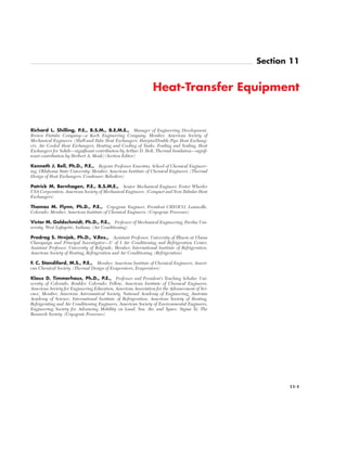
  • 1. 11-1 Section 11 Heat-Transfer Equipment Richard L. Shilling, P.E., B.S.M., B.E.M.E., Manager of Engineering Development, Brown Fintube Company—a Koch Engineering Company; Member, American Society of Mechanical Engineers. (Shell-and-Tube Heat Exchangers, Hairpin/Double Pipe Heat Exchang- ers, Air Cooled Heat Exchangers, Heating and Cooling of Tanks, Fouling and Scaling, Heat Exchangers for Solids—significant contribution by Arthur D. Holt, Thermal Insulation—signif- icant contribution by Herbert A. Moak) (Section Editor) Kenneth J. Bell, Ph.D., P.E., Regents Professor Emeritus, School of Chemical Engineer- ing, Oklahoma State University; Member, American Institute of Chemical Engineers. (Thermal Design of Heat Exchangers, Condenser, Reboilers) Patrick M. Bernhagen, P.E., B.S.M.E., Senior Mechanical Engineer, Foster Wheeler USA Corporation, American Society of Mechanical Engineers. (Compact and Non-Tubular Heat Exchangers) Thomas M. Flynn, Ph.D., P.E., Cryogenic Engineer, President CRYOCO, Louisville, Colorado; Member, American Institute of Chemical Engineers. (Cryogenic Processes) Victor M. Goldschmidt, Ph.D., P.E., Professor of Mechanical Engineering, Purdue Uni- versity, West Lafayette, Indiana. (Air Conditioning) Predrag S. Hrnjak, Ph.D., V.Res., Assistant Professor, University of Illinois at Ubana Champaign and Principal Investigator—U of I Air Conditioning and Refrigeration Center, Assistant Professor, University of Belgrade; Member, International Institute of Refrigeration, American Society of Heating, Refrigeration and Air Conditioning. (Refrigeration) F. C. Standiford, M.S., P.E., Member, American Institute of Chemical Engineers, Ameri- can Chemical Society. (Thermal Design of Evaporators, Evaporators) Klaus D. Timmerhaus, Ph.D., P.E., Professor and President’s Teaching Scholar, Uni- versity of Colorado, Boulder, Colorado; Fellow, American Institute of Chemical Engineers, American Society for Engineering Education, American Association for the Advancement of Sci- ence, Member, American Astronautical Society, National Academy of Engineering, Austrian Academy of Science, International Institute of Refrigeration, American Society of Heating, Refrigerating and Air Conditioning Engineers, American Society of Environmental Engineers, Engineering Society for Advancing Mobility on Land, Sea, Air, and Space, Sigma Xi, The Research Society. (Cryogenic Processes) Copyright © 1999 by The McGraw-Hill Companies, Inc. All rights reserved. Use of this product is subject to the terms of its license agreement. Click here to view.
  • 2. THERMAL DESIGN OF HEAT-TRANSFER EQUIPMENT Introduction to Thermal Design . . . . . . . . . . . . . . . . . . . . . . . . . . . . . . . 11-4 Approach to Heat-Exchanger Design . . . . . . . . . . . . . . . . . . . . . . . . . 11-4 Overall Heat-Transfer Coefficient . . . . . . . . . . . . . . . . . . . . . . . . . . . . 11-4 Mean Temperature Difference . . . . . . . . . . . . . . . . . . . . . . . . . . . . . . 11-4 Countercurrent or Cocurrent Flow . . . . . . . . . . . . . . . . . . . . . . . . . . . 11-4 Reversed, Mixed, or Cross-Flow . . . . . . . . . . . . . . . . . . . . . . . . . . . . . 11-5 Thermal Design for Single-Phase Heat Transfer . . . . . . . . . . . . . . . . . . 11-5 Double-Pipe Heat Exchangers . . . . . . . . . . . . . . . . . . . . . . . . . . . . . . 11-5 Baffled Shell-and-Tube Exchangers . . . . . . . . . . . . . . . . . . . . . . . . . . 11-7 Thermal Design of Condensers . . . . . . . . . . . . . . . . . . . . . . . . . . . . . . . . 11-11 Single-Component Condenser. . . . . . . . . . . . . . . . . . . . . . . . . . . . . . . 11-11 Multicomponent Condensers. . . . . . . . . . . . . . . . . . . . . . . . . . . . . . . . 11-12 Thermal Design of Reboilers . . . . . . . . . . . . . . . . . . . . . . . . . . . . . . . . . . 11-13 Kettle Reboilers . . . . . . . . . . . . . . . . . . . . . . . . . . . . . . . . . . . . . . . . . . 11-13 Vertical Thermosiphon Reboilers . . . . . . . . . . . . . . . . . . . . . . . . . . . . 11-13 Forced-Recirculation Reboilers. . . . . . . . . . . . . . . . . . . . . . . . . . . . . . 11-13 Thermal Design of Evaporators. . . . . . . . . . . . . . . . . . . . . . . . . . . . . . . . 11-13 Forced-Circulation Evaporators . . . . . . . . . . . . . . . . . . . . . . . . . . . . . 11-13 Long-Tube Vertical Evaporators . . . . . . . . . . . . . . . . . . . . . . . . . . . . . 11-14 Short-Tube Vertical Evaporators . . . . . . . . . . . . . . . . . . . . . . . . . . . . . 11-15 Miscellaneous Evaporator Types . . . . . . . . . . . . . . . . . . . . . . . . . . . . . 11-15 Heat Transfer from Various Metal Surfaces . . . . . . . . . . . . . . . . . . . . 11-16 Effect of Fluid Properties on Heat Transfer . . . . . . . . . . . . . . . . . . . . 11-17 Effect of Noncondensables on Heat Transfer . . . . . . . . . . . . . . . . . . . 11-18 Batch Operations: Heating and Cooling of Vessels. . . . . . . . . . . . . . . . . 11-18 Nomenclature . . . . . . . . . . . . . . . . . . . . . . . . . . . . . . . . . . . . . . . . . . . . 11-18 Applications. . . . . . . . . . . . . . . . . . . . . . . . . . . . . . . . . . . . . . . . . . . . . . 11-18 Effect of External Heat Loss or Gain . . . . . . . . . . . . . . . . . . . . . . . . . 11-19 Internal Coil or Jacket Plus External Heat Exchange. . . . . . . . . . . . . 11-19 Equivalent-Area Concept. . . . . . . . . . . . . . . . . . . . . . . . . . . . . . . . . . . 11-19 Nonagitated Batches. . . . . . . . . . . . . . . . . . . . . . . . . . . . . . . . . . . . . . . 11-19 Storage Tanks . . . . . . . . . . . . . . . . . . . . . . . . . . . . . . . . . . . . . . . . . . . . 11-19 Thermal Design of Tank Coils . . . . . . . . . . . . . . . . . . . . . . . . . . . . . . . . . 11-20 Nomenclature . . . . . . . . . . . . . . . . . . . . . . . . . . . . . . . . . . . . . . . . . . . . 11-20 Maintenance of Temperature. . . . . . . . . . . . . . . . . . . . . . . . . . . . . . . . 11-20 Heating . . . . . . . . . . . . . . . . . . . . . . . . . . . . . . . . . . . . . . . . . . . . . . . . . 11-20 Heating and Cooling of Tanks . . . . . . . . . . . . . . . . . . . . . . . . . . . . . . . . . 11-20 Tank Coils . . . . . . . . . . . . . . . . . . . . . . . . . . . . . . . . . . . . . . . . . . . . . . . 11-20 Teflon Immersion Coils . . . . . . . . . . . . . . . . . . . . . . . . . . . . . . . . . . . . 11-21 Bayonet Heaters . . . . . . . . . . . . . . . . . . . . . . . . . . . . . . . . . . . . . . . . . . 11-22 External Coils and Tracers . . . . . . . . . . . . . . . . . . . . . . . . . . . . . . . . . . 11-22 Jacketed Vessels . . . . . . . . . . . . . . . . . . . . . . . . . . . . . . . . . . . . . . . . . . 11-22 Extended or Finned Surfaces. . . . . . . . . . . . . . . . . . . . . . . . . . . . . . . . . . 11-22 Finned-Surface Application . . . . . . . . . . . . . . . . . . . . . . . . . . . . . . . . . 11-22 High Fins . . . . . . . . . . . . . . . . . . . . . . . . . . . . . . . . . . . . . . . . . . . . . . . 11-22 Low Fins . . . . . . . . . . . . . . . . . . . . . . . . . . . . . . . . . . . . . . . . . . . . . . . . 11-23 Fouling and Scaling . . . . . . . . . . . . . . . . . . . . . . . . . . . . . . . . . . . . . . . . . 11-23 Control of Fouling . . . . . . . . . . . . . . . . . . . . . . . . . . . . . . . . . . . . . . . . 11-23 Fouling Transients and Operating Periods . . . . . . . . . . . . . . . . . . . . . 11-23 Removal of Fouling Deposits. . . . . . . . . . . . . . . . . . . . . . . . . . . . . . . . 11-24 Fouling Resistances . . . . . . . . . . . . . . . . . . . . . . . . . . . . . . . . . . . . . . . 11-24 Typical Heat-Transfer Coefficients . . . . . . . . . . . . . . . . . . . . . . . . . . . . . 11-24 Thermal Design for Solids Processing. . . . . . . . . . . . . . . . . . . . . . . . . . . 11-24 Conductive Heat Transfer . . . . . . . . . . . . . . . . . . . . . . . . . . . . . . . . . . 11-24 Contactive (Direct) Heat Transfer. . . . . . . . . . . . . . . . . . . . . . . . . . . . 11-28 Convective Heat Transfer. . . . . . . . . . . . . . . . . . . . . . . . . . . . . . . . . . . 11-30 Radiative Heat Transfer . . . . . . . . . . . . . . . . . . . . . . . . . . . . . . . . . . . . 11-30 Scraped-Surface Exchangers . . . . . . . . . . . . . . . . . . . . . . . . . . . . . . . . . . 11-33 TEMA-STYLE SHELL-AND-TUBE HEAT EXCHANGERS Types and Definitions. . . . . . . . . . . . . . . . . . . . . . . . . . . . . . . . . . . . . . . . 11-33 TEMA Numbering and Type Designations. . . . . . . . . . . . . . . . . . . . . 11-33 Functional Definitions . . . . . . . . . . . . . . . . . . . . . . . . . . . . . . . . . . . . . 11-33 General Design Considerations . . . . . . . . . . . . . . . . . . . . . . . . . . . . . . . . 11-35 Selection of Flow Path . . . . . . . . . . . . . . . . . . . . . . . . . . . . . . . . . . . . . 11-35 Construction Codes . . . . . . . . . . . . . . . . . . . . . . . . . . . . . . . . . . . . . . . 11-35 Tube Bundle Vibration . . . . . . . . . . . . . . . . . . . . . . . . . . . . . . . . . . . . . 11-35 Testing. . . . . . . . . . . . . . . . . . . . . . . . . . . . . . . . . . . . . . . . . . . . . . . . . . 11-35 Principal Types of Construction. . . . . . . . . . . . . . . . . . . . . . . . . . . . . . . . 11-36 Fixed-Tube-Sheet Heat Exchangers . . . . . . . . . . . . . . . . . . . . . . . . . . 11-36 U-Tube Heat Exchanger . . . . . . . . . . . . . . . . . . . . . . . . . . . . . . . . . . . 11-39 Packed-Lantern-Ring Exchanger. . . . . . . . . . . . . . . . . . . . . . . . . . . . . 11-39 Outside-Packed Floating-Head Exchanger. . . . . . . . . . . . . . . . . . . . . 11-39 Internal Floating-Head Exchanger . . . . . . . . . . . . . . . . . . . . . . . . . . . 11-40 Pull-Through Floating-Head Exchanger. . . . . . . . . . . . . . . . . . . . . . . 11-40 Falling-Film Exchangers . . . . . . . . . . . . . . . . . . . . . . . . . . . . . . . . . . . 11-40 Tube-Side Construction . . . . . . . . . . . . . . . . . . . . . . . . . . . . . . . . . . . . . . 11-40 Tube-Side Header. . . . . . . . . . . . . . . . . . . . . . . . . . . . . . . . . . . . . . . . . 11-40 Special High-Pressure Closures. . . . . . . . . . . . . . . . . . . . . . . . . . . . . . 11-40 Tube-Side Passes. . . . . . . . . . . . . . . . . . . . . . . . . . . . . . . . . . . . . . . . . . 11-40 Tubes . . . . . . . . . . . . . . . . . . . . . . . . . . . . . . . . . . . . . . . . . . . . . . . . . . . 11-40 Rolled Tube Joints . . . . . . . . . . . . . . . . . . . . . . . . . . . . . . . . . . . . . . . . 11-41 Welded Tube Joints . . . . . . . . . . . . . . . . . . . . . . . . . . . . . . . . . . . . . . . 11-41 Double-Tube-Sheet Joints . . . . . . . . . . . . . . . . . . . . . . . . . . . . . . . . . . 11-41 Shell-Side Construction . . . . . . . . . . . . . . . . . . . . . . . . . . . . . . . . . . . . . . 11-41 Shell Sizes . . . . . . . . . . . . . . . . . . . . . . . . . . . . . . . . . . . . . . . . . . . . . . . 11-41 Shell-Side Arrangements . . . . . . . . . . . . . . . . . . . . . . . . . . . . . . . . . . . 11-41 Baffles and Tube Bundles. . . . . . . . . . . . . . . . . . . . . . . . . . . . . . . . . . . . . 11-42 Segmental Baffles . . . . . . . . . . . . . . . . . . . . . . . . . . . . . . . . . . . . . . . . . 11-42 Rod Baffles . . . . . . . . . . . . . . . . . . . . . . . . . . . . . . . . . . . . . . . . . . . . . . 11-42 Tie Rods and Spacers . . . . . . . . . . . . . . . . . . . . . . . . . . . . . . . . . . . . . . 11-43 Impingement Baffle . . . . . . . . . . . . . . . . . . . . . . . . . . . . . . . . . . . . . . . 11-43 Vapor Distribution . . . . . . . . . . . . . . . . . . . . . . . . . . . . . . . . . . . . . . . . 11-43 Tube-Bundle Bypassing . . . . . . . . . . . . . . . . . . . . . . . . . . . . . . . . . . . . 11-43 Longitudinal Flow Baffles . . . . . . . . . . . . . . . . . . . . . . . . . . . . . . . . . . 11-43 Corrosion in Heat Exchangers . . . . . . . . . . . . . . . . . . . . . . . . . . . . . . . . . 11-43 Materials of Construction. . . . . . . . . . . . . . . . . . . . . . . . . . . . . . . . . . . 11-43 Bimetallic Tubes . . . . . . . . . . . . . . . . . . . . . . . . . . . . . . . . . . . . . . . . . . 11-43 Clad Tube Sheets . . . . . . . . . . . . . . . . . . . . . . . . . . . . . . . . . . . . . . . . . 11-44 Nonmetallic Construction . . . . . . . . . . . . . . . . . . . . . . . . . . . . . . . . . . 11-44 Fabrication . . . . . . . . . . . . . . . . . . . . . . . . . . . . . . . . . . . . . . . . . . . . . . 11-44 Shell-and-Tube Exchanger Costs. . . . . . . . . . . . . . . . . . . . . . . . . . . . . . . 11-44 HAIRPIN/DOUBLE-PIPE HEAT EXCHANGERS Principles of Construction . . . . . . . . . . . . . . . . . . . . . . . . . . . . . . . . . . . . 11-46 Finned Double Pipes . . . . . . . . . . . . . . . . . . . . . . . . . . . . . . . . . . . . . . . . 11-46 Multitube Hairpins. . . . . . . . . . . . . . . . . . . . . . . . . . . . . . . . . . . . . . . . . . 11-46 Design Applications . . . . . . . . . . . . . . . . . . . . . . . . . . . . . . . . . . . . . . . . . 11-47 AIR-COOLED HEAT EXCHANGERS Air Cooled Heat Exchangers . . . . . . . . . . . . . . . . . . . . . . . . . . . . . . . . . . 11-47 Forced and Induced Draft . . . . . . . . . . . . . . . . . . . . . . . . . . . . . . . . . . 11-47 Tube Bundle . . . . . . . . . . . . . . . . . . . . . . . . . . . . . . . . . . . . . . . . . . . . . 11-48 Tubing . . . . . . . . . . . . . . . . . . . . . . . . . . . . . . . . . . . . . . . . . . . . . . . . . . 11-48 Finned-Tube Construction. . . . . . . . . . . . . . . . . . . . . . . . . . . . . . . . . . 11-49 Fans. . . . . . . . . . . . . . . . . . . . . . . . . . . . . . . . . . . . . . . . . . . . . . . . . . . . 11-49 Fan Drivers . . . . . . . . . . . . . . . . . . . . . . . . . . . . . . . . . . . . . . . . . . . . . . 11-49 Fan Ring and Plenum Chambers. . . . . . . . . . . . . . . . . . . . . . . . . . . . . 11-50 Air-Flow Control. . . . . . . . . . . . . . . . . . . . . . . . . . . . . . . . . . . . . . . . . . 11-50 Air Recirculation. . . . . . . . . . . . . . . . . . . . . . . . . . . . . . . . . . . . . . . . . . 11-50 Trim Coolers . . . . . . . . . . . . . . . . . . . . . . . . . . . . . . . . . . . . . . . . . . . . . 11-50 Humidification Chambers . . . . . . . . . . . . . . . . . . . . . . . . . . . . . . . . . . 11-50 Evaporative Cooling . . . . . . . . . . . . . . . . . . . . . . . . . . . . . . . . . . . . . . . 11-50 Steam Condensers . . . . . . . . . . . . . . . . . . . . . . . . . . . . . . . . . . . . . . . . 11-51 Air-Cooled Overhead Condensers . . . . . . . . . . . . . . . . . . . . . . . . . . . . 11-51 Air-Cooled Heat-Exchanger Costs. . . . . . . . . . . . . . . . . . . . . . . . . . . . 11-51 Design Considerations . . . . . . . . . . . . . . . . . . . . . . . . . . . . . . . . . . . . . 11-51 COMPACT AND NONTUBULAR HEAT EXCHANGERS Compact Heat Exchangers. . . . . . . . . . . . . . . . . . . . . . . . . . . . . . . . . . . . 11-52 Plate-and-Frame Exchangers. . . . . . . . . . . . . . . . . . . . . . . . . . . . . . . . . . 11-52 Gasketed-Plate Exchangers . . . . . . . . . . . . . . . . . . . . . . . . . . . . . . . . . . . 11-52 Description . . . . . . . . . . . . . . . . . . . . . . . . . . . . . . . . . . . . . . . . . . . . . . 11-52 Applications. . . . . . . . . . . . . . . . . . . . . . . . . . . . . . . . . . . . . . . . . . . . . . 11-52 Design . . . . . . . . . . . . . . . . . . . . . . . . . . . . . . . . . . . . . . . . . . . . . . . . . . 11-53 Welded- and Brazed-Plate Exchangers . . . . . . . . . . . . . . . . . . . . . . . . . . 11-55 Spiral-Plate Exchangers . . . . . . . . . . . . . . . . . . . . . . . . . . . . . . . . . . . . . . 11-55 Description . . . . . . . . . . . . . . . . . . . . . . . . . . . . . . . . . . . . . . . . . . . . . . 11-55 Applications. . . . . . . . . . . . . . . . . . . . . . . . . . . . . . . . . . . . . . . . . . . . . . 11-55 Design . . . . . . . . . . . . . . . . . . . . . . . . . . . . . . . . . . . . . . . . . . . . . . . . . . 11-55 Brazed-Plate-Fin Exchangers . . . . . . . . . . . . . . . . . . . . . . . . . . . . . . . . . 11-56 Plate-Fin Tubular Exchangers (PFE) . . . . . . . . . . . . . . . . . . . . . . . . . . . 11-56 Description . . . . . . . . . . . . . . . . . . . . . . . . . . . . . . . . . . . . . . . . . . . . . . 11-56 Applications. . . . . . . . . . . . . . . . . . . . . . . . . . . . . . . . . . . . . . . . . . . . . . 11-56 Design . . . . . . . . . . . . . . . . . . . . . . . . . . . . . . . . . . . . . . . . . . . . . . . . . . 11-56 Spiral-Tube Exchangers (STE) . . . . . . . . . . . . . . . . . . . . . . . . . . . . . . . . 11-56 Description . . . . . . . . . . . . . . . . . . . . . . . . . . . . . . . . . . . . . . . . . . . . . . 11-56 Applications. . . . . . . . . . . . . . . . . . . . . . . . . . . . . . . . . . . . . . . . . . . . . . 11-56 Design . . . . . . . . . . . . . . . . . . . . . . . . . . . . . . . . . . . . . . . . . . . . . . . . . . 11-56 Graphite Heat Exchangers. . . . . . . . . . . . . . . . . . . . . . . . . . . . . . . . . . . . 11-57 Description . . . . . . . . . . . . . . . . . . . . . . . . . . . . . . . . . . . . . . . . . . . . . . 11-57 Applications and Design. . . . . . . . . . . . . . . . . . . . . . . . . . . . . . . . . . . . 11-57 Cascade Coolers . . . . . . . . . . . . . . . . . . . . . . . . . . . . . . . . . . . . . . . . . . . . 11-57 Bayonet-Tube Exchangers . . . . . . . . . . . . . . . . . . . . . . . . . . . . . . . . . . . . 11-57 Atmospheric Sections . . . . . . . . . . . . . . . . . . . . . . . . . . . . . . . . . . . . . . . . 11-57 Nonmetallic Heat Exchangers . . . . . . . . . . . . . . . . . . . . . . . . . . . . . . . . . 11-57 PVDF Heat Exchangers. . . . . . . . . . . . . . . . . . . . . . . . . . . . . . . . . . . . . . 11-57 Ceramic Heat Exchangers . . . . . . . . . . . . . . . . . . . . . . . . . . . . . . . . . . . . 11-58 Teflon Heat Exchangers . . . . . . . . . . . . . . . . . . . . . . . . . . . . . . . . . . . . . . 11-58 11-2 HEAT-TRANSFER EQUIPMENT Copyright © 1999 by The McGraw-Hill Companies, Inc. All rights reserved. Use of this product is subject to the terms of its license agreement. Click here to view.
  • 3. HEAT EXCHANGERS FOR SOLIDS Equipment for Solidification . . . . . . . . . . . . . . . . . . . . . . . . . . . . . . . . . . 11-58 Table Type. . . . . . . . . . . . . . . . . . . . . . . . . . . . . . . . . . . . . . . . . . . . . . . 11-58 Agitated-Pan Type . . . . . . . . . . . . . . . . . . . . . . . . . . . . . . . . . . . . . . . . 11-58 Vibratory Type. . . . . . . . . . . . . . . . . . . . . . . . . . . . . . . . . . . . . . . . . . . . 11-59 Belt Types . . . . . . . . . . . . . . . . . . . . . . . . . . . . . . . . . . . . . . . . . . . . . . . 11-59 Rotating-Drum Type . . . . . . . . . . . . . . . . . . . . . . . . . . . . . . . . . . . . . . 11-60 Rotating-Shelf Type . . . . . . . . . . . . . . . . . . . . . . . . . . . . . . . . . . . . . . . 11-61 Equipment for Fusion of Solids. . . . . . . . . . . . . . . . . . . . . . . . . . . . . . . . 11-61 Horizontal-Tank Type. . . . . . . . . . . . . . . . . . . . . . . . . . . . . . . . . . . . . . 11-61 Vertical Agitated-Kettle Type. . . . . . . . . . . . . . . . . . . . . . . . . . . . . . . . 11-61 Mill Type . . . . . . . . . . . . . . . . . . . . . . . . . . . . . . . . . . . . . . . . . . . . . . . . 11-61 Heat-Transfer Equipment for Sheeted Solids. . . . . . . . . . . . . . . . . . . . . 11-62 Cylinder Heat-Transfer Units . . . . . . . . . . . . . . . . . . . . . . . . . . . . . . . 11-62 Heat-Transfer Equipment for Divided Solids. . . . . . . . . . . . . . . . . . . . . 11-62 Fluidized-Bed Type . . . . . . . . . . . . . . . . . . . . . . . . . . . . . . . . . . . . . . . 11-62 Moving-Bed Type . . . . . . . . . . . . . . . . . . . . . . . . . . . . . . . . . . . . . . . . . 11-63 Agitated-Pan Type . . . . . . . . . . . . . . . . . . . . . . . . . . . . . . . . . . . . . . . . 11-63 Kneading Devices. . . . . . . . . . . . . . . . . . . . . . . . . . . . . . . . . . . . . . . . . 11-63 Shelf Devices . . . . . . . . . . . . . . . . . . . . . . . . . . . . . . . . . . . . . . . . . . . . 11-63 Rotating-Shell Devices . . . . . . . . . . . . . . . . . . . . . . . . . . . . . . . . . . . . . 11-63 Conveyor-Belt Devices. . . . . . . . . . . . . . . . . . . . . . . . . . . . . . . . . . . . . 11-64 Spiral-Conveyor Devices . . . . . . . . . . . . . . . . . . . . . . . . . . . . . . . . . . . 11-64 Double-Cone Blending Devices . . . . . . . . . . . . . . . . . . . . . . . . . . . . . 11-65 Vibratory-Conveyor Devices . . . . . . . . . . . . . . . . . . . . . . . . . . . . . . . . 11-65 Elevator Devices. . . . . . . . . . . . . . . . . . . . . . . . . . . . . . . . . . . . . . . . . . 11-67 Pneumatic-Conveying Devices . . . . . . . . . . . . . . . . . . . . . . . . . . . . . . 11-67 Vacuum-Shelf Types . . . . . . . . . . . . . . . . . . . . . . . . . . . . . . . . . . . . . . . 11-67 THERMAL INSULATION Insulation Materials . . . . . . . . . . . . . . . . . . . . . . . . . . . . . . . . . . . . . . . . . 11-68 Materials . . . . . . . . . . . . . . . . . . . . . . . . . . . . . . . . . . . . . . . . . . . . . . . . 11-68 Thermal Conductivity (K Factor). . . . . . . . . . . . . . . . . . . . . . . . . . . . . 11-68 Finishes . . . . . . . . . . . . . . . . . . . . . . . . . . . . . . . . . . . . . . . . . . . . . . . . . 11-68 System Selection. . . . . . . . . . . . . . . . . . . . . . . . . . . . . . . . . . . . . . . . . . . . 11-69 Cryogenic High Vacuum . . . . . . . . . . . . . . . . . . . . . . . . . . . . . . . . . . . 11-69 Low Temperature . . . . . . . . . . . . . . . . . . . . . . . . . . . . . . . . . . . . . . . . . 11-69 Moderate and High Temperature . . . . . . . . . . . . . . . . . . . . . . . . . . . . 11-69 Economic Thickness of Insulation. . . . . . . . . . . . . . . . . . . . . . . . . . . . . . 11-70 Recommended Thickness of Insulation. . . . . . . . . . . . . . . . . . . . . . . . 11-70 Example 1 . . . . . . . . . . . . . . . . . . . . . . . . . . . . . . . . . . . . . . . . . . . . . . . 11-73 Example 2 . . . . . . . . . . . . . . . . . . . . . . . . . . . . . . . . . . . . . . . . . . . . . . . 11-73 Example 3 . . . . . . . . . . . . . . . . . . . . . . . . . . . . . . . . . . . . . . . . . . . . . . . 11-73 Installation Practice . . . . . . . . . . . . . . . . . . . . . . . . . . . . . . . . . . . . . . . . . 11-73 Pipe . . . . . . . . . . . . . . . . . . . . . . . . . . . . . . . . . . . . . . . . . . . . . . . . . . . . 11-73 Method of Securing . . . . . . . . . . . . . . . . . . . . . . . . . . . . . . . . . . . . . . . 11-73 Double Layer . . . . . . . . . . . . . . . . . . . . . . . . . . . . . . . . . . . . . . . . . . . . 11-73 Finish. . . . . . . . . . . . . . . . . . . . . . . . . . . . . . . . . . . . . . . . . . . . . . . . . . . 11-73 Tanks, Vessels, and Equipment . . . . . . . . . . . . . . . . . . . . . . . . . . . . . . 11-73 Method of Securing . . . . . . . . . . . . . . . . . . . . . . . . . . . . . . . . . . . . . . . 11-73 Finish. . . . . . . . . . . . . . . . . . . . . . . . . . . . . . . . . . . . . . . . . . . . . . . . . . . 11-74 AIR CONDITIONING Introduction . . . . . . . . . . . . . . . . . . . . . . . . . . . . . . . . . . . . . . . . . . . . . . . 11-74 Comfort Air Conditioning . . . . . . . . . . . . . . . . . . . . . . . . . . . . . . . . . . . . 11-74 Industrial Air Conditioning . . . . . . . . . . . . . . . . . . . . . . . . . . . . . . . . . . . 11-74 Ventilation . . . . . . . . . . . . . . . . . . . . . . . . . . . . . . . . . . . . . . . . . . . . . . . . . 11-74 Air-Conditioning Equipment . . . . . . . . . . . . . . . . . . . . . . . . . . . . . . . . . . 11-74 Central Systems . . . . . . . . . . . . . . . . . . . . . . . . . . . . . . . . . . . . . . . . . . . . 11-75 Unitary Refrigerant-Based Air-Conditioning Systems . . . . . . . . . . . . . . 11-75 Load Calculation. . . . . . . . . . . . . . . . . . . . . . . . . . . . . . . . . . . . . . . . . . . . 11-76 REFRIGERATION Introduction . . . . . . . . . . . . . . . . . . . . . . . . . . . . . . . . . . . . . . . . . . . . . . . 11-76 Basic Principles. . . . . . . . . . . . . . . . . . . . . . . . . . . . . . . . . . . . . . . . . . . 11-76 Basic Refrigeration Methods . . . . . . . . . . . . . . . . . . . . . . . . . . . . . . . . 11-76 Mechanical Refrigeration (Vapor-Compression Systems) . . . . . . . . . . . 11-77 Vapor-Compression Cycles. . . . . . . . . . . . . . . . . . . . . . . . . . . . . . . . . . 11-77 Multistage Systems . . . . . . . . . . . . . . . . . . . . . . . . . . . . . . . . . . . . . . . . 11-78 Cascade System. . . . . . . . . . . . . . . . . . . . . . . . . . . . . . . . . . . . . . . . . . . 11-79 Equipment . . . . . . . . . . . . . . . . . . . . . . . . . . . . . . . . . . . . . . . . . . . . . . . . 11-79 Compressors . . . . . . . . . . . . . . . . . . . . . . . . . . . . . . . . . . . . . . . . . . . . . 11-79 Positive-Displacement Compressors . . . . . . . . . . . . . . . . . . . . . . . . . . 11-80 Centrifugal Compressors . . . . . . . . . . . . . . . . . . . . . . . . . . . . . . . . . . . 11-83 Condensers . . . . . . . . . . . . . . . . . . . . . . . . . . . . . . . . . . . . . . . . . . . . . . 11-83 Evaporators. . . . . . . . . . . . . . . . . . . . . . . . . . . . . . . . . . . . . . . . . . . . . . 11-84 System Analysis. . . . . . . . . . . . . . . . . . . . . . . . . . . . . . . . . . . . . . . . . . . 11-85 System, Equipment, and Refrigerant Selection . . . . . . . . . . . . . . . . . 11-87 Other Refrigerant Systems Applied in the Industry . . . . . . . . . . . . . . . . 11-88 Absorption Refrigeration Systems . . . . . . . . . . . . . . . . . . . . . . . . . . . . 11-88 Steam-Jet (Ejector) Systems . . . . . . . . . . . . . . . . . . . . . . . . . . . . . . . . 11-89 Multistage Systems . . . . . . . . . . . . . . . . . . . . . . . . . . . . . . . . . . . . . . . . 11-93 Capacity Control. . . . . . . . . . . . . . . . . . . . . . . . . . . . . . . . . . . . . . . . . . 11-93 Refrigerants. . . . . . . . . . . . . . . . . . . . . . . . . . . . . . . . . . . . . . . . . . . . . . 11-93 Secondary Refrigerants (Antifreezes or Brines) . . . . . . . . . . . . . . . . . 11-94 Organic Compounds (Inhibited Glycols). . . . . . . . . . . . . . . . . . . . . . . 11-95 Safety in Refrigeration Systems . . . . . . . . . . . . . . . . . . . . . . . . . . . . . . 11-96 CRYOGENIC PROCESSES Introduction . . . . . . . . . . . . . . . . . . . . . . . . . . . . . . . . . . . . . . . . . . . . . . . 11-96 Properties of Cryogenic Fluids . . . . . . . . . . . . . . . . . . . . . . . . . . . . . . . . 11-96 Properties of Solids. . . . . . . . . . . . . . . . . . . . . . . . . . . . . . . . . . . . . . . . . . 11-96 Structural Properties at Low Temperatures . . . . . . . . . . . . . . . . . . . . 11-97 Thermal Properties at Low Temperatures . . . . . . . . . . . . . . . . . . . . . 11-97 Electrical Properties at Low Temperatures. . . . . . . . . . . . . . . . . . . . . 11-97 Superconductivity. . . . . . . . . . . . . . . . . . . . . . . . . . . . . . . . . . . . . . . . . 11-97 Refrigeration and Liquifaction. . . . . . . . . . . . . . . . . . . . . . . . . . . . . . . . . 11-98 Principles. . . . . . . . . . . . . . . . . . . . . . . . . . . . . . . . . . . . . . . . . . . . . . . . 11-98 Expansion Types of Refrigerators . . . . . . . . . . . . . . . . . . . . . . . . . . . . 11-98 Miniature Refrigerators . . . . . . . . . . . . . . . . . . . . . . . . . . . . . . . . . . . . 11-100 Thermodynamic Analyses of Cycles. . . . . . . . . . . . . . . . . . . . . . . . . . . 11-100 Process Equipment. . . . . . . . . . . . . . . . . . . . . . . . . . . . . . . . . . . . . . . . . . 11-100 Heat Exchangers. . . . . . . . . . . . . . . . . . . . . . . . . . . . . . . . . . . . . . . . . . 11-101 Expanders . . . . . . . . . . . . . . . . . . . . . . . . . . . . . . . . . . . . . . . . . . . . . . . 11-101 Separation and Purification Systems . . . . . . . . . . . . . . . . . . . . . . . . . . . . 11-102 Air-Separation Systems. . . . . . . . . . . . . . . . . . . . . . . . . . . . . . . . . . . . . 11-102 Helium and Natural-Gas Systems Separation . . . . . . . . . . . . . . . . . . . 11-103 Gas Purification . . . . . . . . . . . . . . . . . . . . . . . . . . . . . . . . . . . . . . . . . . 11-103 Storage and Transfer Systems . . . . . . . . . . . . . . . . . . . . . . . . . . . . . . . . . 11-104 Insulation Principles. . . . . . . . . . . . . . . . . . . . . . . . . . . . . . . . . . . . . . . 11-104 Types of Insulation . . . . . . . . . . . . . . . . . . . . . . . . . . . . . . . . . . . . . . . . 11-104 Storage and Transfer Systems . . . . . . . . . . . . . . . . . . . . . . . . . . . . . . . 11-105 Cryogenic Instrumentation . . . . . . . . . . . . . . . . . . . . . . . . . . . . . . . . . . . 11-106 Pressure. . . . . . . . . . . . . . . . . . . . . . . . . . . . . . . . . . . . . . . . . . . . . . . . . 11-106 Liquid Level . . . . . . . . . . . . . . . . . . . . . . . . . . . . . . . . . . . . . . . . . . . . . 11-106 Flow. . . . . . . . . . . . . . . . . . . . . . . . . . . . . . . . . . . . . . . . . . . . . . . . . . . . 11-106 Temperature . . . . . . . . . . . . . . . . . . . . . . . . . . . . . . . . . . . . . . . . . . . . . 11-106 Safety. . . . . . . . . . . . . . . . . . . . . . . . . . . . . . . . . . . . . . . . . . . . . . . . . . . . . 11-106 Physiological Hazards. . . . . . . . . . . . . . . . . . . . . . . . . . . . . . . . . . . . . . 11-107 Materials and Construction Hazards . . . . . . . . . . . . . . . . . . . . . . . . . . 11-107 Flammability and Explosion Hazards . . . . . . . . . . . . . . . . . . . . . . . . . 11-107 High-Pressure Gas Hazards . . . . . . . . . . . . . . . . . . . . . . . . . . . . . . . . . 11-107 Summary . . . . . . . . . . . . . . . . . . . . . . . . . . . . . . . . . . . . . . . . . . . . . . . . . . 11-107 EVAPORATORS Primary Design Problems . . . . . . . . . . . . . . . . . . . . . . . . . . . . . . . . . . . . 11-107 Heat Transfer . . . . . . . . . . . . . . . . . . . . . . . . . . . . . . . . . . . . . . . . . . . . 11-107 Vapor-Liquid Separation . . . . . . . . . . . . . . . . . . . . . . . . . . . . . . . . . . . 11-107 Selection Problems . . . . . . . . . . . . . . . . . . . . . . . . . . . . . . . . . . . . . . . . 11-107 Product Quality. . . . . . . . . . . . . . . . . . . . . . . . . . . . . . . . . . . . . . . . . . . 11-108 Evaporator Types and Applications . . . . . . . . . . . . . . . . . . . . . . . . . . . . . 11-108 Forced-Circulation Evaporators . . . . . . . . . . . . . . . . . . . . . . . . . . . . . 11-108 Short-Tube Vertical Evaporators . . . . . . . . . . . . . . . . . . . . . . . . . . . . . 11-109 Long-Tube Vertical Evaporators . . . . . . . . . . . . . . . . . . . . . . . . . . . . . 11-109 Horizontal-Tube Evaporators. . . . . . . . . . . . . . . . . . . . . . . . . . . . . . . . 11-110 Miscellaneous Forms of Heating Surface . . . . . . . . . . . . . . . . . . . . . . 11-111 Evaporators without Heating Surfaces . . . . . . . . . . . . . . . . . . . . . . . . 11-111 Utilization of Temperature Difference . . . . . . . . . . . . . . . . . . . . . . . . . . 11-111 Vapor-Liquid Separation . . . . . . . . . . . . . . . . . . . . . . . . . . . . . . . . . . . . . 11-111 Evaporator Arrangement . . . . . . . . . . . . . . . . . . . . . . . . . . . . . . . . . . . . . 11-113 Single-Effect Evaporators . . . . . . . . . . . . . . . . . . . . . . . . . . . . . . . . . . 11-113 Thermocompression. . . . . . . . . . . . . . . . . . . . . . . . . . . . . . . . . . . . . . . 11-113 Multiple-Effect Evaporation . . . . . . . . . . . . . . . . . . . . . . . . . . . . . . . . 11-113 Seawater Evaporators. . . . . . . . . . . . . . . . . . . . . . . . . . . . . . . . . . . . . . 11-114 Evaporator Calculations . . . . . . . . . . . . . . . . . . . . . . . . . . . . . . . . . . . . . . 11-115 Single-Effect Evaporators . . . . . . . . . . . . . . . . . . . . . . . . . . . . . . . . . . 11-115 Thermocompression Evaporators . . . . . . . . . . . . . . . . . . . . . . . . . . . . 11-115 Flash Evaporators. . . . . . . . . . . . . . . . . . . . . . . . . . . . . . . . . . . . . . . . . 11-115 Multiple-Effect Evaporators . . . . . . . . . . . . . . . . . . . . . . . . . . . . . . . . 11-117 Optimization . . . . . . . . . . . . . . . . . . . . . . . . . . . . . . . . . . . . . . . . . . . . . 11-117 Evaporator Accessories. . . . . . . . . . . . . . . . . . . . . . . . . . . . . . . . . . . . . . . 11-117 Condensers . . . . . . . . . . . . . . . . . . . . . . . . . . . . . . . . . . . . . . . . . . . . . . 11-117 Vent Systems . . . . . . . . . . . . . . . . . . . . . . . . . . . . . . . . . . . . . . . . . . . . . 11-117 Salt Removal . . . . . . . . . . . . . . . . . . . . . . . . . . . . . . . . . . . . . . . . . . . . . 11-117 Evaporator Operation. . . . . . . . . . . . . . . . . . . . . . . . . . . . . . . . . . . . . . . . 11-118 HEAT-TRANSFER EQUIPMENT 11-3 Copyright © 1999 by The McGraw-Hill Companies, Inc. All rights reserved. Use of this product is subject to the terms of its license agreement. Click here to view.
  • 4. THERMAL DESIGN OF HEAT-TRANSFER EQUIPMENT INTRODUCTION TO THERMAL DESIGN Design methods for several important classes of process heat-transfer equipment are presented in the following portions of Sec. 11. Mechanical descriptions and specifications of equipment are given in this section and should be read in conjunction with the use of this material. It is impossible to present here a comprehensive treatment of heat-exchanger selection, design, and application. The best general references in this field are Hewitt, Shires, and Bott, Process Heat Transfer, CRC Press, Boca Raton, FL, 1994; and Schlünder (ed.), Heat Exchanger Design Handbook, Begell House, New York, 1983. Approach to Heat-Exchanger Design The proper use of basic heat-transfer knowledge in the design of practical heat-transfer equip- ment is an art. Designers must be constantly aware of the differences between the idealized conditions for and under which the basic knowledge was obtained and the real conditions of the mechanical expression of their design and its environment. The result must satisfy process and operational requirements (such as availability, flexibility, and maintainability) and do so economically. An important part of any design process is to consider and offset the consequences of error in the basic knowledge, in its subsequent incorporation into a design method, in the translation of design into equipment, or in the opera- tion of the equipment and the process. Heat-exchanger design is not a highly accurate art under the best of conditions. The design of a process heat exchanger usually proceeds through the following steps: 1. Process conditions (stream compositions, flow rates, tempera- tures, pressures) must be specified. 2. Required physical properties over the temperature and pres- sure ranges of interest must be obtained. 3. The type of heat exchanger to be employed is chosen. 4. A preliminary estimate of the size of the exchanger is made, using a heat-transfer coefficient appropriate to the fluids, the process, and the equipment. 5. A first design is chosen, complete in all details necessary to carry out the design calculations. 6. The design chosen in step 5 is evaluated, or rated, as to its abil- ity to meet the process specifications with respect to both heat trans- fer and pressure drop. 7. On the basis of the result of step 6, a new configuration is cho- sen if necessary and step 6 is repeated. If the first design was inade- quate to meet the required heat load, it is usually necessary to increase the size of the exchanger while still remaining within specified or fea- sible limits of pressure drop, tube length, shell diameter, etc. This will sometimes mean going to multiple-exchanger configurations. If the first design more than meets heat-load requirements or does not use all the allowable pressure drop, a less expensive exchanger can usually be designed to fulfill process requirements. 8. The final design should meet process requirements (within rea- sonable expectations of error) at lowest cost. The lowest cost should include operation and maintenance costs and credit for ability to meet long-term process changes, as well as installed (capital) cost. Exchangers should not be selected entirely on a lowest-first-cost basis, which frequently results in future penalties. Overall Heat-Transfer Coefficient The basic design equation for a heat exchanger is dA = dQ/U ∆T (11-1) where dA is the element of surface area required to transfer an amount of heat dQ at a point in the exchanger where the overall heat- transfer coefficient is U and where the overall bulk temperature dif- ference between the two streams is ∆T. The overall heat-transfer coefficient is related to the individual film heat-transfer coefficients and fouling and wall resistances by Eq. (11-2). Basing Uo on the out- side surface area Ao results in Uo = (11-2) Equation (11-1) can be formally integrated to give the outside area required to transfer the total heat load QT: Ao = E QT 0 (11-3) To integrate Eq. (11-3), Uo and ∆T must be known as functions of Q. For some problems, Uo varies strongly and nonlinearly throughout the exchanger. In these cases, it is necessary to evaluate Uo and ∆T at sev- eral intermediate values and numerically or graphically integrate. For many practical cases, it is possible to calculate a constant mean overall coefficient Uom from Eq. (11-2) and define a corresponding mean value of ∆Tm, such that Ao = QT /Uom ∆Tm (11-4) Care must be taken that Uo does not vary too strongly, that the proper equations and conditions are chosen for calculating the indi- vidual coefficients, and that the mean temperature difference is the correct one for the specified exchanger configuration. Mean Temperature Difference The temperature difference between the two fluids in the heat exchanger will, in general, vary from point to point. The mean temperature difference (∆Tm or MTD) can be calculated from the terminal temperatures of the two streams if the following assumptions are valid: 1. All elements of a given fluid stream have the same thermal his- tory in passing through the exchanger.* 2. The exchanger operates at steady state. 3. The specific heat is constant for each stream (or if either stream undergoes an isothermal phase transition). 4. The overall heat-transfer coefficient is constant. 5. Heat losses are negligible. Countercurrent or Cocurrent Flow If the flow of the streams is either completely countercurrent or completely cocurrent or if one or both streams are isothermal (condensing or vaporizing a pure com- ponent with negligible pressure change), the correct MTD is the log- arithmic-mean temperature difference (LMTD), defined as LMTD = ∆Tlm = (11-5a) for countercurrent flow (Fig. 11-1a) and LMTD = ∆Tlm = (11-5b) for cocurrent flow (Fig. 11-1b) If U is not constant but a linear function of ∆T, the correct value of (t′ 1 − t″ 1) − (t′ 2 − t″ 2 ) }}} ln 1} t t ′ ′ 1 2 − − t t ″ ″ 1 2 }2 (t′ 1 − t″ 2 ) − (t′ 2 − t1 ″) }}} ln 1} t t ′ ′ 1 2 − − t t ″ ″ 2 1 }2 dQ } Uo ∆T 1 }}}}} 1/ho + Rdo + xAo/kw Awm + (1/hi + Rdi)Ao/Ai 11-4 * This assumption is vital but is usually omitted or less satisfactorily stated as “each stream is well mixed at each point.” In a heat exchanger with substantial bypass- ing of the heat-transfer surface, e.g., a typical baffled shell-and-tube exchanger, this condition is not satisfied. However, the error is in some degree offset if the same MTD formulation used in reducing experimental heat-transfer data to obtain the basic correlation is used in applying the correlation to design a heat exchanger. The compensation is not in general exact, and insight and judgment are required in the use of the MTD formulations. Particularly, in the design of an exchanger with a very close temperature approach, bypassing may result in an exchanger that is inefficient and even thermodynamically incapable of meeting specified outlet temperatures. Copyright © 1999 by The McGraw-Hill Companies, Inc. All rights reserved. Use of this product is subject to the terms of its license agreement. Click here to view.
  • 5. Uom ∆Tm to use in Eq. (11-4) is [Colburn, Ind. Eng. Chem., 25, 873 (1933)] Uom ∆Tm = (11-6a) for countercurrent flow, where U″ o is the overall coefficient evaluated when the stream temperatures are t′ 1 and t″ 2 and U′ o is evaluated at t′ 2 and t″ 1. The corresponding equation for cocurrent flow is Uom ∆Tm = (11-6b) where U′ o is evaluated at t′ 2 and t″ 2 and U″ o is evaluated at t′ 1 and t″ 1. To use these equations, it is necessary to calculate two values of Uo.* The use of Eq. (11-6) will frequently give satisfactory results even if Uo is not strictly linear with temperature difference. Reversed, Mixed, or Cross-Flow If the flow pattern in the exchanger is not completely countercurrent or cocurrent, it is neces- sary to apply a correction factor FT by which the LMTD is multiplied to obtain the appropriate MTD. These corrections have been mathe- matically derived for flow patterns of interest, still by making assump- tions 1 to 5 [see Bowman, Mueller, and Nagle, Trans. Am. Soc. Mech. Eng., 62, 283 (1940) or Hewitt, et al. op. cit.]. For a common flow pat- tern, the 1-2 exchanger (Fig. 11-2), the correction factor FT is given in Fig. 11-4a, which is also valid for finding FT for a 1-2 exchanger in which the shell-side flow direction is reversed from that shown in Fig. 11-2. Figure 11-4a is also applicable with negligible error to exchang- ers with one shell pass and any number of tube passes. Values of FT less than 0.8 (0.75 at the very lowest) are generally unacceptable because the exchanger configuration chosen is inefficient; the chart is difficult to read accurately; and even a small violation of the first assumption underlying the MTD will invalidate the mathematical derivation and lead to a thermodynamically inoperable exchanger. Correction-factor charts are also available for exchangers with more Uo ″(t′ 1 − t″ 1) − U′ o(t′ 2 − t″ 2 ) }}} ln 1} U U o ″ ′ o ( ( t t ′ 1 ′ 2 − − t t 1 ″ 2 ″ ) ) }2 Uo ″(t′ 1 − t″ 2) − U′ o(t′ 2 − t″ 1) }}} ln 1} U U o ′ o ″ ( ( t t ′2 ′ 1 − − t t 1 ″ 2 ″ ) ) }2 than one shell pass provided by a longitudinal shell-side baffle. How- ever, these exchangers are seldom used in practice because of mechanical complications in their construction. Also thermal and physical leakages across the longitudinal baffle further reduce the mean temperature difference and are not properly incorporated into the correction-factor charts. Such charts are useful, however, when it is necessary to construct a multiple-shell exchanger train such as that shown in Fig. 11-3 and are included here for two, three, four, and six separate identical shells and two or more tube passes per shell in Fig. 11-4b, c, d, and e. If only one tube pass per shell is required, the pip- ing can and should be arranged to provide pure countercurrent flow, in which case the LMTD is used with no correction. Cross-flow exchangers of various kinds are also important and require correction to be applied to the LMTD calculated by assuming countercurrent flow. Several cases are given in Fig. 11-4f, g, h, i, and j. Many other MTD correction-factor charts have been prepared for various configurations. The FT charts are often employed to make approximate corrections for configurations even in cases for which they are not completely valid. THERMAL DESIGN FOR SINGLE-PHASE HEAT TRANSFER Double-Pipe Heat Exchangers The design of double-pipe heat exchangers is straightforward. It is generally conservative to neglect natural-convection and entrance effects in turbulent flow. In laminar flow, natural convection effects can increase the theoretical Graetz prediction by a factor of 3 or 4 for fully developed flows. Pres- sure drop is calculated by using the correlations given in Sec. 6. If the inner tube is longitudinally finned on the outside surface, the equivalent diameter is used as the characteristic length in both the Reynolds-number and the heat-transfer correlations. The fin effi- THERMAL DESIGN OF HEAT-TRANSFER EQUIPMENT 11-5 FIG. 11-1 Temperature profiles in heat exchangers. (a) Countercurrent. (b) Cocurrent. (b) (a) FIG. 11-2 Diagram of a 1-2 exchanger (one well-baffled shell pass and two tube passes with an equal number of tubes in each pass). FIG. 11-3 Diagram of a 2-4 exchanger (two separate identical well-baffled shells and four or more tube passes). * This task can be avoided if a hydrocarbon stream is the limiting resistance by the use of the caloric temperature charts developed by Colburn [Ind. Eng. Chem., 25, 873 (1933)]. Copyright © 1999 by The McGraw-Hill Companies, Inc. All rights reserved. Use of this product is subject to the terms of its license agreement. Click here to view.
  • 6. 11-6 HEAT-TRANSFER EQUIPMENT FIG. 11-4 LMTD correction factors for heat exchangers. In all charts, R = (T1 − T2)/(t2 − t1) and S = (t2 − t1)/(T1 − t1). (a) One shell pass, two or more tube passes. (b) Two shell passes, four or more tube passes. (c) Three shell passes, six or more tube passes. (d) Four shell passes, eight or more tube passes. (e) Six shell passes, twelve or more tube passes. (f) Cross-flow, one shell pass, one or more parallel rows of tubes. (g) Cross-flow, two passes, two rows of tubes; for more than two passes, use FT = 1.0. (h) Cross-flow, one shell pass, one tube pass, both fluids unmixed (g) (e) (c) (a) (h) (f) (d) (b) Copyright © 1999 by The McGraw-Hill Companies, Inc. All rights reserved. Use of this product is subject to the terms of its license agreement. Click here to view.
  • 7. ciency must also be known to calculate an effective outside area to use in Eq. (11-2). Fittings contribute strongly to the pressure drop on the annulus side. General methods for predicting this are not reliable, and manu- facturer’s data should be used when available. Double-pipe exchangers are often piped in complex series-parallel arrangements on both sides. The MTD to be used has been derived for some of these arrangements and is reported in Kern (Process Heat Transfer, McGraw-Hill, New York, 1950). More complex cases may require trial-and-error balancing of the heat loads and rate equations for subsections or even for individual exchangers in the bank. Baffled Shell-and-Tube Exchangers The method given here is based on the research summarized in Final Report, Cooperative Research Program on Shell and Tube Heat Exchangers, Univ. Del. Eng. Exp. Sta. Bull. 5 (June 1963). The method assumes that the shell-side heat transfer and pressure-drop characteristics are equal to those of the ideal tube bank corresponding to the cross-flow sections of the exchanger, modified for the distortion of flow pattern intro- duced by the baffles and the presence of leakage and bypass flow through the various clearances required by mechanical construction. It is assumed that process conditions and physical properties are known and the following are known or specified: tube outside diame- ter Do, tube geometrical arrangement (unit cell), shell inside diameter Ds, shell outer tube limit Dotl, baffle cut lc, baffle spacing ls, and num- ber of sealing strips Nss. The effective tube length between tube sheets L may be either specified or calculated after the heat-transfer coeffi- cient has been determined. If additional specific information (e.g., tube-baffle clearance) is available, the exact values (instead of esti- mates) of certain parameters may be used in the calculation with some improvement in accuracy. To complete the rating, it is necessary to know also the tube material and wall thickness or inside diameter. This rating method, though apparently generally the best in the open literature, is not extremely accurate. An exhaustive study by Palen and Taborek [Chem. Eng. Prog. Symp. Ser. 92, 65, 53 (1969)] showed that this method predicted shell-side coefficients from about 50 percent low to 100 percent high, while the pressure-drop range was from about 50 percent low to 200 percent high. The mean error for heat transfer was about 15 percent low (safe) for all Reynolds numbers, while the mean error for pressure drop was from about 5 percent low (unsafe) at Reynolds numbers above 1000 to about 100 percent high at Reynolds numbers below 10. Calculation of Shell-Side Geometrical Parameters 1. Total number of tubes in exchanger Nt. If not known by direct count, estimate using Eq. (11-84) or (11-85). 2. Tube pitch parallel to flow pp and normal to flow pn. These quantities are needed only for estimating other parameters. If a detailed drawing of the exchanger is available, it is better to obtain these other parameters by direct count or calculation. The pitches are described by Fig. 11-5 and read therefrom for common tube layouts. 3. Number of tube rows crossed in one cross-flow section Nc. Count from exchanger drawing or estimate from THERMAL DESIGN OF HEAT-TRANSFER EQUIPMENT 11-7 FIG. 11-5 Values of tube pitch for common tube layouts. To convert inches to meters, multiply by 0.0254. Not that Do, p′, pp, and pn have units of inches. FIG. 11-4 (Continued) LMTD correction factors for heat exchangers. In all charts, R = (T1 − T2)/(t2 − t1) and S = (t2 − t1)/(T1 − t1). (i) Cross-flow (drip type), two hor- izontal passes with U-bend connections (trombone type). (j) Cross-flow (drip type), helical coils with two turns. (i) (j) Nc = (11-7) 4. Fraction of total tubes in cross-flow Fc Fc = 3π + 2 sin 1cos−1 2− 2 cos−1 4 (11-8) Fc is plotted in Fig. 11-6. This figure is strictly applicable only to split- ring, floating-head construction but may be used for other situations with minor error. 5. Number of effective cross-flow rows in each window Ncw Ncw = (11-9) 0.8lc } pp Ds − 2lc } Dotl Ds − 2lc } Dotl Ds − 2lc } Dotl 1 } π Ds[1 − 2(lc /Ds)] }} pp Copyright © 1999 by The McGraw-Hill Companies, Inc. All rights reserved. Use of this product is subject to the terms of its license agreement. Click here to view.
  • 8. 6. Cross-flow area at or near centerline for one cross-flow sec- tion Sm a. For rotated and in-line square layouts: Sm = ls 3Ds − Dotl + (p′ − Do) 4m2 (ft2 ) (11-10a) b. For triangular layouts: Sm = ls 3Ds − Dotl + (p′ − Do) 4m2 (ft2 ) (11-10b) 7. Fraction of cross-flow area available for bypass flow Fbp Fbp = (11-11) 8. Tube-to-baffle leakage area for one baffle Stb. Estimate from Stb = bDo NT(1 + Fc ) m2 (ft2 ) (11-12) where b = (6.223)(10−4 ) (SI) or (1.701)(10−4 ) (U.S. customary). These values are based on Tubular Exchanger Manufacturers Association (TEMA) Class R construction which specifies h-in diametral clear- ance between tube and baffle. Values should be modified if extra tight or loose construction is specified or if clogging by dirt is antici- pated. 9. Shell-to-baffle leakage area for one baffle Ssb. If diametral shell- baffle clearance δsb is known, Ssb can be calculated from Ssb = 3π − cos−1 11 − 24 m2 (ft2 ) (11-13) where the value of the term cos−1 (1 − 2lc /Ds) is in radians and is between 0 and π/2. Ssb is plotted in Fig. 11-7, based on TEMA Class R standards. Since pipe shells are generally limited to diameters below 24 in, the larger sizes are shown by using the rolled-shell spec- ification. Allowance should be made for especially tight or loose con- struction. 10. Area for flow through window Sw. This area is obtained as the difference between the gross window area Swg and the window area occupied by tubes Swt: 2lc } Ds Ds δsb } 2 (Ds − Dotl)ls }} Sm Dotl − Do } p′ Dotl − Do } pn Sw = Swg − Swt (11-14) Swg = 3cos−1 11 − 2 2 − 11 − 2 2!1 §− §1 §1 §− §2 §§§2 2 §4 m2 (ft2 ) (11-15) Swg is plotted in Fig. 11-8. Swt can be calculated from Swt = (NT/8)(1 − Fc)π Do 2 m2 (ft2 ) (11-16) 11. Equivalent diameter of window Dw [required only if laminar flow, defined as (NRe)s ≤ 100, exists] Dw = m (ft) (11-17) where θb is the baffle-cut angle given by θb = 2 cos−1 11 − 2 rad (11-18) 12. Number of baffles Nb Nb = + 1 (11-19) where le is the entrance/exit baffle spacing, often different from the central baffle spacing. The effective tube length L must be known to calculate Nb, which is needed to calculate shell-side pressure drop. In designing an exchanger, the shell-side coefficient may be calculated and the required exchanger length for heat transfer obtained before Nb is calculated. Shell-Side Heat-Transfer Coefficient Calculation 1. Calculate the shell-side Reynolds number (NRe)s. (NRe)s = DoW/µbSm (11-20) where W = mass flow rate and µb = viscosity at bulk temperature. The arithmetic mean bulk shell-side fluid temperature is usually adequate L − 2le } ls 2lc } Ds 4Sw }}} (π/2)NT(1 − Fc) Do + Dsθb lc } Ds lc } Ds lc } Ds Ds 2 } 4 11-8 HEAT-TRANSFER EQUIPMENT FIG. 11-7 Estimation of shell-to-baffle leakage area [Eq. (11-13)]. To convert inches to meters, multiply by 0.0254; to convert square inches to square meters, multiply by (6.45)(10−4 ). Note that lc and Ds have units of inches. FIG. 11-6 Estimation of fraction of tubes in cross-flow Fc [Eq. (11-8)]. To con- vert inches to meters, multiply by 0.0254. Note that lc and Ds have units of inches. Copyright © 1999 by The McGraw-Hill Companies, Inc. All rights reserved. Use of this product is subject to the terms of its license agreement. Click here to view.
  • 9. to evaluate all bulk properties of the shell-side fluid. For large tem- perature ranges or for viscosity that is very sensitive to temperature change, special care must be taken, such as using Eq. (11-6). 2. Find jk from the ideal-tube bank curve for a given tube layout at the calculated value of (NRe)s, using Fig. 11-9, which is adapted from ideal-tube-bank data obtained at Delaware by Bergelin et al. [Trans. Am. Soc. Mech. Eng., 74, 953 (1952) and the Grimison correlation [Trans. Am. Soc. Mech. Eng., 59, 583 (1937)]. 3. Calculate the shell-side heat-transfer coefficient for an ideal tube bank hk. hk = jkc 1 2 2/3 1 2 0.14 (11-21) where c is the specific heat, k is the thermal conductivity, and µw is the viscosity evaluated at the mean surface temperature. 4. Find the correction factor for baffle-configuration effects Jc from Fig. 11-10. 5. Find the correction factor for baffle-leakage effects Jl from Fig. 11-11. 6. Find the correction factor for bundle-bypassing effects Jb from Fig. 11-12 7. Find the correction factor for adverse temperature-gradient buildup at low Reynolds number Jr: a. If (NRe)s < 100, find J* r from Fig. 11-13, knowing Nb and (Nc + Ncw). b. If (NRe)s ≤ 20, Jr = J* r . c. If 20 < (NRe)s < 100, find Jr from Fig. 11-14, knowing J* r and (NRe)s. 8. Calculate the shell-side heat-transfer coefficient for the exchanger hs from hs = hk Jc Jl Jb Jr (11-22) µb } µw k } cµ W } Sm THERMAL DESIGN OF HEAT-TRANSFER EQUIPMENT 11-9 FIG. 11-8 Estimation of window cross-flow area [Eq. (11-15)]. To convert inches to meters, multiply by 0.0254. Note that lc and Ds have units of inches. FIG. 11-9 Correlation of j factor for ideal tube bank. To convert inches to meters, multiply by 0.0254. Note that p′ and Do have units of inches. FIG. 11-10 Correction factor for baffle-configuration effects. FIG. 11-11 Correction factor for baffle-leakage effects. Copyright © 1999 by The McGraw-Hill Companies, Inc. All rights reserved. Use of this product is subject to the terms of its license agreement. Click here to view.
  • 10. Shell-Side Pressure-Drop Calculation 1. Find fk from the ideal-tube-bank friction-factor curve for the given tube layout at the calculated value of (NRe)s, using Fig. 11-15a for triangular and rotated square arrays and Fig. 11-15b for in-line square arrays. These curves are adapted from Bergelin et al. and Grimison (loc. cit.). 2. Calculate the pressure drop for an ideal cross-flow section. ∆Pbk = b 1 2 0.14 (11-23) where b = (2.0)(10−3 ) (SI) or (9.9)(10−5 ) (U.S. customary). 3. Calculate the pressure drop for an ideal window section. If (NRe)s ≥ 100, ∆Pwk = b (11-24a) where b = (5)(10−4 ) (SI) or (2.49)(10−5 ) (U.S. customary). If (NRe)s < 100, ∆Pwk = b1 1 + 2+ b2 (11-24b) where b1 = (1.681)(10−5 ) (SI) or (1.08)(10−4 ) (U.S. customary), and b2 = (9.99)(10−4 ) (SI) or (4.97)(10−5 ) (U.S. customary). 4. Find the correction factor for the effect of baffle leakage on pressure drop Rl from Fig. 11-16. Curves shown are not to be extrap- olated beyond the points shown. 5. Find the correction factor for bundle bypass Rb from Fig. 11-17. 6. Calculate the pressure drop across the shell side (excluding nozzles). Units for pressure drop are lbf/ft2 . ∆Ps = [(Nb − 1)(∆Pbk)Rb + Nb ∆Pwk]Rl + 2 ∆PbkRb 11 + 2 (11-25) The values of hs and ∆Ps calculated by this procedure are for clean exchangers and are intended to be as accurate as possible, not conser- vative. A fouled exchanger will generally give lower heat-transfer rates, as reflected by the dirt resistances incorporated into Eq. (11-2), and higher pressure drops. Some estimate of fouling effects on pres- Ncw } Nc W2 } SmSwρ ls } Dw 2 Ncw } p′ − Do µbW } SmSwρ W2 (2 + 0.6Ncw) }} SmSwρ µw } µb fkW2 Nc } ρSm 2 11-10 HEAT-TRANSFER EQUIPMENT FIG. 11-14 Correction factor for adverse temperature gradient at intermedi- ate Reynolds numbers. FIG. 11-15 Correction of friction factors for ideal tube banks. (a) Triangular and rotated square arrays. (b) In-line square arrays. (b) (a) FIG. 11-12 Correction factor for bypass flow. FIG. 11-13 Basic correction factor for adverse temperature gradient at low Reynolds numbers. Copyright © 1999 by The McGraw-Hill Companies, Inc. All rights reserved. Use of this product is subject to the terms of its license agreement. Click here to view.
  • 11. sure drop may be made by using the methods just given by assuming that the fouling deposit blocks the leakage and possibly the bypass areas. The fouling may also decrease the clearance between tubes and significantly increase the pressure drop in cross-flow. THERMAL DESIGN OF CONDENSERS Single-Component Condensers Mean Temperature Difference In condensing a single compo- nent at its saturation temperature, the entire resistance to heat trans- fer on the condensing side is generally assumed to be in the layer of condensate. A mean condensing coefficient is calculated from the appropriate correlation and combined with the other resistances in Eq. (11-2). The overall coefficient is then used with the LMTD (no FT correction is necessary for isothermal condensation) to give the required area, even though the condensing coefficient and hence U are not constant throughout the condenser. If the vapor is superheated at the inlet, the vapor may first be desuperheated by sensible heat transfer from the vapor. This occurs if the surface temperature is above the saturation temperature, and a single-phase heat-transfer correlation is used. If the surface is below the saturation temperature, condensation will occur directly from the superheated vapor, and the effective coefficient is determined from the appropriate condensation correlation, using the saturation tem- perature in the LMTD. To determine whether or not condensation will occur directly from the superheated vapor, calculate the surface temperature by assuming single-phase heat transfer. Tsurface = Tvapor − (Tvapor − Tcoolant) (11-26) where h is the sensible heat-transfer coefficient for the vapor, U is calculated by using h, and both are on the same area basis. If Tsurface > Tsaturation, no condensation occurs at that point and the heat flux is actu- ally higher than if Tsurface ≤ Tsaturation and condensation did occur. It is generally conservative to design a pure-component desuperheater- condenser as if the entire heat load were transferred by condensation, using the saturation temperature in the LMTD. The design of an integral condensate subcooling section is more difficult, especially if close temperature approach is required. The condensate layer on the surface is on the average subcooled by one- third to one-half of the temperature drop across the film, and this is often sufficient if the condensate is not reheated by raining through the vapor. If the condensing-subcooling process is carried out inside tubes or in the shell of a vertical condenser, the single-phase subcool- ing section can be treated separately, giving an area that is added onto that needed for condensation. If the subcooling is achieved on the shell side of a horizontal condenser by flooding some of the bottom tubes with a weir or level controller, the rate and heat-balance equa- tions must be solved for each section to obtain the area required. Pressure drop on the condensing side reduces the final condens- ing temperature and the MTD and should always be checked. In designs requiring close approach between inlet coolant and exit con- densate (subcooled or not), underestimation of pressure drop on the condensing side can lead to an exchanger that cannot meet specified terminal temperatures. Since pressure-drop calculations in two-phase flows such as condensation are relatively inaccurate, designers must consider carefully the consequences of a larger-than-calculated pres- sure drop. Horizontal In-Shell Condensers The mean condensing co- efficient for the outside of a bank of horizontal tubes is calculated from Eq. (5-93) for a single tube, corrected for the number of tubes in a vertical row. For undisturbed laminar flow over all the tubes, Eq. (5-97) is, for realistic condenser sizes, overly conservative because of rippling, splashing, and turbulent flow (Process Heat Transfer, McGraw-Hill, New York, 1950). Kern proposed an exponent of −j on the basis of experience, while Freon-11 data of Short and Brown (General Discussion on Heat Transfer, Institute of Mechanical Engi- neers, London, 1951) indicate independence of the number of tube rows. It seems reasonable to use no correction for inviscid liquids and Kern’s correction for viscous condensates. For a cylindrical tube bun- dle, where N varies, it is customary to take N equal to two-thirds of the maximum or centerline value. U } h THERMAL DESIGN OF HEAT-TRANSFER EQUIPMENT 11-11 FIG. 11-16 Correction factor for baffle-leakage effect on pressure drop. FIG. 11-17 Correction factor on pressure drop for bypass flow. Copyright © 1999 by The McGraw-Hill Companies, Inc. All rights reserved. Use of this product is subject to the terms of its license agreement. Click here to view.
  • 12. Baffles in a horizontal in-shell condenser are oriented with the cuts vertical to facilitate drainage and eliminate the possibility of flooding in the upward cross-flow sections. Pressure drop on the vapor side can be estimated by the data and method of Diehl and Unruh [Pet. Refiner, 36(10), 147 (1957); 37(10), 124 (1958)]. High vapor velocities across the tubes enhance the condensing coef- ficient. There is no correlation in the open literature to permit design- ers to take advantage of this. Since the vapor flow rate varies along the length, an incremental calculation procedure would be required in any case. In general, the pressure drops required to gain significant benefit are above those allowed in most process applications. Vertical In-Shell Condensers Condensers are often designed so that condensation occurs on the outside of vertical tubes. Equation (5-88) is valid as long as the condensate film is laminar. When it becomes turbulent, Fig. 5-10 or Colburn’s equation [Trans. Am. Inst. Chem. Eng., 30, 187 (1933–1934) may be used. Some judgment is required in the use of these correlations because of construction features of the condenser. The tubes must be sup- ported by baffles, usually with maximum cut (45 percent of the shell diameter) and maximum spacing to minimize pressure drop. The flow of the condensate is interrupted by the baffles, which may draw off or redistribute the liquid and which will also cause some splashing of free-falling drops onto the tubes. For subcooling, a liquid inventory may be maintained in the bot- tom end of the shell by means of a weir or a liquid-level-controller. The subcooling heat-transfer coefficient is given by the correlations for natural convection on a vertical surface [Eqs. (5-33a), (5-33b)], with the pool assumed to be well mixed (isothermal) at the subcooled condensate exit temperature. Pressure drop may be estimated by the shell-side procedure. Horizontal In-Tube Condensers Condensation of a vapor inside horizontal tubes occurs in kettle and horizontal thermosiphon reboilers and in air-cooled condensers. In-tube condensation also offers certain advantages for condensation of multicomponent mix- tures, discussed in the subsection “Multicomponent Condensers.” The various in-tube correlations are closely connected to the two- phase flow pattern in the tube [Chem. Eng. Prog. Symp. Ser., 66(102), 150 (1970)]. At low flow rates, when gravity dominates the flow pattern, Eq. (5-101) may be used. At high flow rates, the flow and heat transfer are governed by vapor shear on the condensate film, and Eq. (5-100a) is valid. A simple and generally conservative procedure is to calculate the coefficient for a given case by both correlations and use the larger one. Pressure drop during condensation inside horizontal tubes can be computed by using the correlations for two-phase flow given in Sec. 6 and neglecting the pressure recovery due to deceleration of the flow. Vertical In-Tube Condensation Vertical-tube condensers are generally designed so that vapor and liquid flow cocurrently down- ward; if pressure drop is not a limiting consideration, this configura- tion can result in higher heat-transfer coefficients than shell-side condensation and has particular advantages for multicomponent con- densation. If gravity controls, the mean heat-transfer coefficient for condensation is given by Figs. 5-9 and 5-10. If vapor shear controls, Eq. (5-99a) is applicable. It is generally conservative to calculate the coefficients by both methods and choose the higher value. The pres- sure drop can be calculated by using the Lockhart-Martinelli method [Chem. Eng. Prog., 45, 39 (1945)] for friction loss, neglecting momen- tum and hydrostatic effects. Vertical in-tube condensers are often designed for reflux or knock-back application in reactors or distillation columns. In this case, vapor flow is upward, countercurrent to the liquid flow on the tube wall; the vapor shear acts to thicken and retard the drainage of the condensate film, reducing the coefficient. Neither the fluid dynamics nor the heat transfer is well understood in this case, but Soliman, Schuster, and Berenson [J. Heat Transfer, 90, 267–276 (1968)] discuss the problem and suggest a computational method. The Diehl-Koppany correlation [Chem. Eng. Prog. Symp. Ser. 92, 65 (1969)] may be used to estimate the maximum allowable vapor veloc- ity at the tube inlet. If the vapor velocity is great enough, the liquid film will be carried upward; this design has been employed in a few cases in which only part of the stream is to be condensed. This veloc- ity cannot be accurately computed, and a very conservative (high) out- let velocity must be used if unstable flow and flooding are to be avoided; 3 times the vapor velocity given by the Diehl-Koppany cor- relation for incipient flooding has been suggested as the design value for completely stable operation. Multicomponent Condensers Thermodynamic and Mass-Transfer Considerations Multi- component vapor mixture includes several different cases: all the com- ponents may be liquids at the lowest temperature reached in the condensing side, or there may be components which dissolve substan- tially in the condensate even though their boiling points are below the exit temperature, or one or more components may be both noncon- densable and nearly insoluble. Multicomponent condensation always involves sensible-heat changes in the vapor and liquid along with the latent-heat load. Compositions of both phases in general change through the condenser, and concentra- tion gradients exist in both phases. Temperature and concentration profiles and transport rates at a point in the condenser usually cannot be calculated, but the binary cases have been treated: condensation of one component in the presence of a completely insoluble gas [Colburn and Hougen, Ind. Eng. Chem., 26, 1178–1182 (1934); and Colburn and Edison, Ind. Eng. Chem., 33, 457–458 (1941)] and condensation of a binary vapor [Colburn and Drew, Trans. Am. Inst. Chem. Eng., 33, 196–215 (1937)]. It is necessary to know or calculate diffusion coeffi- cients for the system, and a reasonable approximate method to avoid this difficulty and the reiterative calculations is desirable. To integrate the point conditions over the total condensation requires the tempera- ture, composition enthalpy, and flow-rate profiles as functions of the heat removed. These are calculated from component thermodynamic data if the vapor and liquid are assumed to be in equilibrium at the local vapor temperature. This assumption is not exactly true, since the con- densate and the liquid-vapor interface (where equilibrium does exist) are intermediate in temperature between the coolant and the vapor. In calculating the condensing curve, it is generally assumed that the vapor and liquid flow collinearly and in intimate contact so that com- position equilibrium is maintained between the total streams at all points. If, however, the condensate drops out of the vapor (as can hap- pen in horizontal shell-side condensation) and flows to the exit with- out further interaction, the remaining vapor becomes excessively enriched in light components with a decrease in condensing tempera- ture and in the temperature difference between vapor and coolant. The result may be not only a small reduction in the amount of heat transferred in the condenser but also an inability to condense totally the light ends even at reduced throughput or with the addition of more surface. To prevent the liquid from segregating, in-tube con- densation is preferred in critical cases. Thermal Design If the controlling resistance for heat and mass transfer in the vapor is sensible-heat removal from the cooling vapor, the following design equation is obtained: A = E QT 0 dQ (11-27) U′ is the overall heat-transfer coefficient between the vapor-liquid interface and the coolant, including condensate film, dirt and wall resistances, and coolant. The condensate film coefficient is calculated from the appropriate equation or correlation for pure vapor conden- sation for the geometry and flow regime involved, using mean liquid properties. ZH is the ratio of the sensible heat removed from the vapor-gas stream to the total heat transferred; this quantity is obtained from thermodynamic calculations and may vary substantially from one end of the condenser to the other, especially when removing vapor from a noncondensable gas. The sensible-heat-transfer coefficient for the vapor-gas stream hsv is calculated by using the appropriate correla- tion or design method for the geometry involved, neglecting the pres- ence of the liquid. As the vapor condenses, this coefficient decreases and must be calculated at several points in the process. Tv and Tc are temperatures of the vapor and of the coolant respectively. This proce- dure is similar in principle to that of Ward [Petro/Chem. Eng., 32(11), 42–48 (1960)]. It may be nonconservative for condensing steam and 1 + U′ZH /hsv }} U′(Tv − Tc) 11-12 HEAT-TRANSFER EQUIPMENT Copyright © 1999 by The McGraw-Hill Companies, Inc. All rights reserved. Use of this product is subject to the terms of its license agreement. Click here to view.
  • 13. other high-latent-heat substances, in which case it may be necessary to increase the calculated area by 25 to 50 percent. Pressure drop on the condensing side may be estimated by judi- cious application of the methods suggested for pure-component con- densation, taking into account the generally nonlinear decrease of vapor-gas flow rate with heat removal. THERMAL DESIGN OF REBOILERS For a single-component reboiler design, attention is focused upon the mechanism of heat and momentum transfer at the hot surface. In multicomponent systems, the light components are preferentially vaporized at the surface, and the process becomes limited by their rate of diffusion. The net effect is to decrease the effective tempera- ture difference between the hot surface and the bulk of the boiling liquid. If one attempts to vaporize too high a fraction of the feed liq- uid to the reboiler, the temperature difference between surface and liquid is reduced to the point that nucleation and vapor generation on the surface are suppressed and heat transfer to the liquid proceeds at the lower rate associated with single-phase natural convection. The only safe procedure in design for wide-boiling-range mixtures is to vaporize such a limited fraction of the feed that the boiling point of the remaining liquid mixture is still at least 5.5°C (10°F) below the surface temperature. Positive flow of the unvaporized liquid through and out of the reboiler should be provided. Kettle Reboilers It has been generally assumed that kettle reboilers operate in the pool boiling mode, but with a lower peak heat flux because of vapor binding and blanketing of the upper tubes in the bundle. There is some evidence that vapor generation in the bundle causes a high circulation rate through the bundle. The result is that, at the lower heat fluxes, the kettle reboiler actually gives higher heat- transfer coefficients than a single tube. Present understanding of the recirculation phenomenon is insufficient to take advantage of this in design. Available nucleate pool boiling correlations are only very approximate, failing to account for differences in the nucleation char- acteristics of different surfaces. The Mostinski correlation [Eq. (5-102)] and the McNelly correlation [Eq. (5-103)] are generally the best for single components or narrow-boiling-range mixtures at low fluxes, though they may give errors of 40 to 50 percent. Experimental heat-transfer coefficients for pool boiling of a given liquid on a given surface should be used if available. The bundle peak heat flux is a function of tube-bundle geometry, especially of tube-packing density; in the absence of better information, the Palen-Small modification [Eq. (5-108)] of the Zuber maximum-heat-flux correlation is recom- mended. A general method for analyzing kettle reboiler performance is by Fair and Klip, Chem. Eng. Prog. 79(3), 86 (1983). It is effectively lim- ited to computer application. Kettle reboilers are generally assumed to require negligible pres- sure drop. It is important to provide good longitudinal liquid flow paths within the shell so that the liquid is uniformly distributed along the entire length of the tubes and excessive local vaporization and vapor binding are avoided. This method may also be used for the thermal design of horizontal thermosiphon reboilers. The recirculation rate and pressure profile of the thermosiphon loop can be calculated by the methods of Fair [Pet. Refiner, 39(2), 105–123 (1960)]. Vertical Thermosiphon Reboilers Vertical thermosiphon reboilers operate by natural circulation of the liquid from the still through the downcomer to the reboiler and of the two-phase mixture from the reboiler through the return piping. The flow is induced by the hydrostatic pressure imbalance between the liquid in the down- comer and the two-phase mixture in the reboiler tubes. Thermo- siphons do not require any pump for recirculation and are generally regarded as less likely to foul in service because of the relatively high two-phase velocities obtained in the tubes. Heavy components are not likely to accumulate in the thermosiphon, but they are more difficult to design satisfactorily than kettle reboilers, especially in vacuum operation. Several shortcut methods have been suggested for ther- mosiphon design, but they must generally be used with caution. The method due to Fair (loc. cit.), based upon two-phase flow correlations, is the most complete in the open literature but requires a computer for practical use. Fair also suggests a shortcut method that is satisfac- tory for preliminary design and can be reasonably done by hand. Forced-Recirculation Reboilers In forced-recirculation re- boilers, a pump is used to ensure circulation of the liquid past the heattransfer surface. Force-recirculation reboilers may be designed so that boiling occurs inside vertical tubes, inside horizontal tubes, or on the shell side. For forced boiling inside vertical tubes, Fair’s method (loc. cit.) may be employed, making only the minor modification that the recirculation rate is fixed and does not need to be balanced against the pressure available in the downcomer. Excess pressure required to circulate the two-phase fluid through the tubes and back into the col- umn is supplied by the pump, which must develop a positive pressure increase in the liquid. Fair’s method may also be modified to design forced-recirculation reboilers with horizontal tubes. In this case the hydrostatic-head- pressure effect through the tubes is zero but must be considered in the two-phase return lines to the column. The same procedure may be applied in principle to design of forced-recirculation reboilers with shell-side vapor generation. Little is known about two-phase flow on the shell side, but a reasonable esti- mate of the friction pressure drop can be made from the data of Diehl and Unruh [Pet. Refiner, 36(10), 147 (1957); 37(10), 124 (1958)]. No void-fraction data are available to permit accurate estimation of the hydrostatic or acceleration terms. These may be roughly estimated by assuming homogeneous flow. THERMAL DESIGN OF EVAPORATORS Heat duties of evaporator heating surfaces are usually determined by conventional heat and material balance calculations. Heating surface areas are normally, but not always taken as those in contact with the material being evaporated. It is the heat transfer ∆T that presents the most difficulty in deriving or applying heat-transfer coefficients. The total ∆T between heat source and heat sink is never all available for heat transfer. Since energy usually is carried to and from an evaporator body or effect by condensible vapors, loss in pressure represents a loss in ∆T. Such losses include pressure drop through entrainment separa- tors, friction in vapor piping, and acceleration losses into and out of the piping. The latter loss has often been overlooked, even though it can be many times greater than the friction loss. Similarly, friction and accel- eration losses past the heating surface, such as in a falling film evapo- rator, cause a loss of ∆T that may or may not have been included in the heat transfer ∆T when reporting experimental results. Boiling-point rise, the difference between the boiling point of the solution and the condensing point of the solvent at the same pressure, is another loss. Experimental data are almost always corrected for boiling-point rise, but plant data are suspect when based on temperature measurements because vapor at the point of measurement may still contain some superheat, which represents but a very small fraction of the heat given up when the vapor condenses but may represent a substantial fraction of the actual net ∆T available for heat transfer. A ∆T loss that must be considered in forced-circulation evaporators is that due to temperature rise through the heater, a consequence of the heat being absorbed there as sensible heat. A further loss may occur when the heater efflu- ent flashes as it enters the vapor-liquid separator. Some of the liquid may not reach the surface and flash to equilibrium with the vapor pres- sure in the separator, instead of recirculating to the heater, raising the average temperature at which heat is absorbed and further reducing the net ∆T. Whether or not these ∆T losses are allowed for in the heat- transfer coefficients reported depends on the method of measure- ment. Simply basing the liquid temperature on the measured vapor head pressure may ignore both—or only the latter if temperature rise through the heater is estimated separately from known heat input and circulation rate. In general, when calculating overall heat-transfer coef- ficients from individual-film coefficients, all of these losses must be allowed for, while when using reported overall coefficients care must be exercised to determine which losses may already have been included in the heat transfer ∆T. Forced-Circulation Evaporators In evaporators of this type in which hydrostatic head prevents boiling at the heating surface, heat- THERMAL DESIGN OF HEAT-TRANSFER EQUIPMENT 11-13 Copyright © 1999 by The McGraw-Hill Companies, Inc. All rights reserved. Use of this product is subject to the terms of its license agreement. Click here to view.
  • 14. transfer coefficients can be predicted from the usual correlations for condensing steam (Fig. 5-10) and forced-convection sensible heat- ing [Eq. (5-50)]. The liquid film coefficient is improved if boiling is not completely suppressed. When only the film next to the wall is above the boiling point, Boarts, Badger, and Meisenberg [Ind. Eng. Chem., 29, 912 (1937)] found that results could be correlated by Eq. (5-50) by using a constant of 0.0278 instead of 0.023. In such cases, the course of the liquid temperature can still be calculated from known circulation rate and heat input. When the bulk of the liquid is boiling in part of the tube length, the film coefficient is even higher. However, the liquid temperature starts dropping as soon as full boiling develops, and it is difficult to estimate the course of the temperature curve. It is certainly safe to estimate heat transfer on the basis that no bulk boiling occurs. Fragen and Bad- ger [Ind. Eng. Chem., 28, 534 (1936)] obtained an empirical corre- lation of overall heat-transfer coefficients in this type of evaporator, based on the ∆T at the heater inlet: In U.S. customary units U = 2020D0.57 (Vs)3.6/L /µ0.25 ∆T0.1 (11-28) where D = mean tube diameter, Vs = inlet velocity, L = tube length, and µ = liquid viscosity. This equation is based primarily on experi- ments with copper tubes of 0.022 m (8/8 in) outside diameter, 0.00165 m (16 gauge), 2.44 m (8 ft) long, but it includes some work with 0.0127-m (a-in) tubes 2.44 m (8 ft) long and 0.0254-m (1-in) tubes 3.66 m (12 ft) long. Long-Tube Vertical Evaporators In the rising-film version of this type of evaporator, there is usually a nonboiling zone in the bot- tom section and a boiling zone in the top section. The length of the nonboiling zone depends on heat-transfer characteristics in the two zones and on pressure drop during two-phase flow in the boiling zone. The work of Martinelli and coworkers [Lockhart and Martinelli, Chem. Eng. Prog., 45, 39–48 (January 1949); and Martinelli and Nelson, Trans. Am. Soc. Mech. Eng., 70, 695–702 (August 1948)] per- mits a prediction of pressure drop, and a number of correlations are available for estimating film coefficients of heat transfer in the two zones. In estimating pressure drop, integrated curves similar to those presented by Martinelli and Nelson are the easiest to use. The curves for pure water are shown in Figs. 11-18 and 11-19, based on the assumption that the flow of both vapor and liquid would be turbulent if each were flowing alone in the tube. Similar curves can be prepared if one or both flows are laminar or if the properties of the liquid differ appreciably from the properties of pure water. The acceleration pressure drop ∆Pa is calculated from the equation ∆Pa = br2G2 /32.2 (11-29) where b = (2.6)(107 )(SI) and 1.0 (U.S. customary) and using r2 from Fig. 11-18. The frictional pressure drop is derived from Fig. 11-19, which shows the ratio of two-phase pressure drop to that of the enter- ing liquid flowing alone. Pressure drop due to hydrostatic head can be calculated from liquid holdup R1. For nonfoaming dilute aqueous solutions, R1 can be esti- mated from R1 = 1/[1 + 2.5(V/L)(ρ1 /ρv)1/2 ]. Liquid holdup, which rep- resents the ratio of liquid-only velocity to actual liquid velocity, also appears to be the principal determinant of the convective coefficient in the boiling zone (Dengler, Sc.D. thesis, MIT, 1952). In other words, the convective coefficient is that calculated from Eq. (5-50) by using the liquid-only velocity divided by R1 in the Reynolds number. Nucle- ate boiling augments convective heat transfer, primarily when ∆T’s are high and the convective coefficient is low [Chen, Ind. Eng. Chem. Process Des. Dev., 5, 322 (1966)]. Film coefficients for the boiling of liquids other than water have been investigated. Coulson and McNelly [Trans. Inst. Chem. Eng., 34, 247 (1956)] derived the following relation, which also corre- lated the data of Badger and coworkers [Chem. Metall. Eng., 46, 640 (1939); Chem. Eng., 61(2), 183 (1954); and Trans. Am. Inst. Chem. Eng., 33, 392 (1937); 35, 17 (1939); 36, 759 (1940)] on water: NNu = (1.3 + b D)(NPr)l 0.9 (NRe)l 0.23 (NRe)g 0.34 1 2 0.25 1 2 (11-30) where b = 128 (SI) or 39 (U.S. customary), NNu = Nusselt number based on liquid thermal conductivity, D = tube diameter, and the remaining terms are dimensionless groupings of liquid Prandtl num- ber, liquid Reynolds number, vapor Reynolds number, and ratios of densities and viscosities. The Reynolds numbers are calculated on the basis of each fluid flowing by itself in the tube. Additional corrections must be applied when the fraction of vapor is so high that the remaining liquid does not wet the tube wall or when the velocity of the mixture at the tube exits approaches sonic velocity. McAdams, Woods, and Bryan (Trans. Am. Soc. Mech. Eng., 1940), Dengler and Addoms (loc. cit.), and Stroebe, Baker, and Badger [Ind. Eng. Chem., 31, 200 (1939)] encountered dry-wall conditions and reduced coefficients when the weight fraction of vapor exceeded about 80 percent. Schweppe and Foust [Chem. Eng. Prog., 49, Symp. Ser. 5, 77 (1953)] and Harvey and Foust (ibid., p. 91) found that “sonic choking” occurred at surprisingly low flow rates. The simplified method of calculation outlined includes no allowance for the effect of surface tension. Stroebe, Baker, and Badger (loc. cit.) found that by adding a small amount of surface- µg } µl ρl } ρg 11-14 HEAT-TRANSFER EQUIPMENT FIG. 11-19 Friction pressure drop in boiling flow. °C = (°F − 32)/1.8. FIG. 11-18 Acceleration losses in boiling flow. °C = (°F − 32)/1.8. Copyright © 1999 by The McGraw-Hill Companies, Inc. All rights reserved. Use of this product is subject to the terms of its license agreement. Click here to view.
  • 15. active agent the boiling-film coefficient varied inversely as the square of the surface tension. Coulson and Mehta [Trans. Inst. Chem. Eng., 31, 208 (1953)] found the exponent to be −1.4. The higher coeffi- cients at low surface tension are offset to some extent by a higher pres- sure drop, probably because the more intimate mixture existing at low surface tension causes the liquid fraction to be accelerated to a veloc- ity closer to that of the vapor. The pressure drop due to acceleration ∆Pa derived from Fig. 11-18 allows for some slippage. In the limiting case, such as might be approached at low surface tension, the acceler- ation pressure drop in which “fog” flow is assumed (no slippage) can be determined from the equation ∆P′ a = (11-31) where y = fraction vapor by weight Vg, Vl = specific volume gas, liquid G = mass velocity While the foregoing methods are valuable for detailed evaporator design or for evaluating the effect of changes in conditions on perfor- mance, they are cumbersome to use when making preliminary designs or cost estimates. Figure 11-20 gives the general range of overall long-tube vertical- (LTV) evaporator heat-transfer coefficients usually encountered in commercial practice. The higher coefficients are encountered when evaporating dilute solutions and the lower range when evaporating viscous liquids. The dashed curve represents the approximate lower limit, for liquids with viscosities of about 0.1 Pa⋅s (100 cP). The LTV evaporator does not work well at low tem- perature differences, as indicated by the results shown in Fig. 11-21 for seawater in 0.051-m (2-in), 0.0028-m (12-gauge) brass tubes 7.32 m (24 ft) long (W. L. Badger Associates, Inc., U.S. Department of the Interior, Office of Saline Water Rep. 26, December 1959, OTS Publ. PB 161290). The feed was at its boiling point at the vapor-head pressure, and feed rates varied from 0.025 to 0.050 kg/(s⋅tube) [200 to 400 lb/(h⋅tube)] at the higher temperature to 0.038 to 0.125 kg/ (s⋅tube) [300 to 1000 lb/(h⋅tube)] at the lowest temperature. Falling film evaporators find their widest use at low temperature differences—also at low temperatures. Under most operating con- ditions encountered, heat transfer is almost all by pure convection, with a negligible contribution from nucleate boiling. Film coef- ficients on the condensing side may be estimated from Dukler’s correlation, [Chem. Eng. Prog. 55, 62 1950]. The same Dukler cor- relation presents curves covering falling film heat transfer to non- boiling liquids that are equally applicable to the falling film evaporator [Sinek and Young, Chem. Eng. Prog. 58, No. 12, 74 (1962)]. Kunz and Yerazunis [ J. Heat Transfer 8, 413 (1969)] have y(Vg − Vl )G2 }} gc since extended the range of physical properties covered, as shown in Fig. 11-22. The boiling point in the tubes of such an evaporator is higher than in the vapor head because of both frictional-pressure drop and the head needed to accelerate the vapor to the tube-exit velocity. These factors, which can easily be predicted, make the over- all apparent coefficients somewhat lower than those for nonboiling conditions. Figure 11-21 shows overall apparent heat-transfer coeffi- cients determined in a falling-film seawater evaporator using the same tubes and flow rates as for the rising-film tests (W. L. Badger Associates, Inc., loc. cit.). Short-Tube Vertical Evaporators Coefficients can be estimated by the same detailed method described for recirculating LTV evapora- tors. Performance is primarily a function of temperature level, temper- ature difference, and viscosity. While liquid level can also have an important influence, this is usually encountered only at levels lower than considered safe in commercial operation. Overall heat-transfer coefficients are shown in Fig. 11-23 for a basket-type evaporator (one with an annular downtake) when boiling water with 0.051-m (2-in) outside-diameter 0.0028-m-wall (12-gauge), 1.22-m-(4-ft-) long steel tubes [Badger and Shepard, Chem. Metall. Eng., 23, 281 (1920)]. Liq- uid level was maintained at the top tube sheet. Foust, Baker, and Badger [Ind. Eng. Chem., 31, 206 (1939)] measured recirculating velocities and heat-transfer coefficients in the same evaporator except with 0.064-m (2.5-in) 0.0034-m-wall (10-gauge), 1.22-m- (4-ft-) long tubes and temperature differences from 7 to 26°C (12 to 46°F). In the normal range of liquid levels, their results can be expressed as Uc = (11-32) where b = 153 (SI) or 375 (U.S. customary) and the subscript c refers to true liquid temperature, which under these conditions was about 0.56°C (1°F) above the vapor-head temperature. This work was done with water. No detailed tests have been reported for the performance of pro- peller calandrias. Not enough is known regarding the performance of the propellers themselves under the cavitating conditions usually encountered to permit predicting circulation rates. In many cases, it appears that the propeller does no good in accelerating heat transfer over the transfer for natural circulation (Fig. 11-23). Miscellaneous Evaporator Types Horizontal-tube evapora- tors operating with partially or fully submerged heating surfaces behave in much the same way as short-tube verticals, and heat- transfer coefficients are of the same order of magnitude. Some test results for water were published by Badger [Trans. Am. Inst. Chem. Eng., 13, 139 (1921)]. When operating unsubmerged, their heat transfer performance is roughly comparable to the falling-film vertical tube evaporator. Condensing coefficients inside the tubes can be derived from Nusselt’s theory which, based on a constant-heat flux rather than a constant film ∆T, gives: b(∆Tc)0.22 NPr 0.4 }} (Vg − Vl)0.37 THERMAL DESIGN OF HEAT-TRANSFER EQUIPMENT 11-15 FIG. 11-21 Heat-transfer coefficients in LTV seawater evaporators. °C = (°F − 32)/1.8; to convert British thermal units per hour-square foot-degrees Fahrenheit to joules per square meter-second-kelvins, multiply by 5.6783. FIG. 11-20 General range of long-tube vertical- (LTV) evaporator coefficients. °C = (°F − 32)/1.8; to convert British thermal units per hour-square foot-degrees Fahrenheit to joules per square meter-second-kelvins, multiply by 5.6783. Copyright © 1999 by The McGraw-Hill Companies, Inc. All rights reserved. Use of this product is subject to the terms of its license agreement. Click here to view.
  • 16. = 1.59(4Γ/µ)−1/3 (11-33a) For the boiling side, a correlation based on seawater tests gave: = 0.0147(4Γ/µ)1/3 (D)−1/3 (11-33b) where Γ is based on feed-rate per unit length of the top tube in each vertical row of tubes and D is in meters. Heat-transfer coefficients in clean coiled-tube evaporators for sea- water are shown in Fig. 11-24 [Hillier, Proc. Inst. Mech. Eng. (Lon- don), 1B(7), 295 (1953)]. The tubes were of copper. Heat-transfer coefficients in agitated-film evaporators depend primarily on liquid viscosity. This type is usually justifiable only for very viscous materials. Figure 11-25 shows general ranges of overall coefficients [Hauschild, Chem. Ing. Tech., 25, 573 (1953); Lindsey, Chem. Eng., 60(4), 227 (1953); and Leniger and Veldstra, Chem. Ing. Tech., 31, 493 (1959)]. When used with nonviscous fluids, a wiped- film evaporator having fluted external surfaces can exhibit very high coefficients (Lustenader et al., Trans. Am. Soc. Mech. Eng., Paper 59- SA-30, 1959), although at a probably unwarranted first cost. Heat Transfer from Various Metal Surfaces In an early work, Pridgeon and Badger [Ind. Eng. Chem., 16, 474 (1924)] published test results on copper and iron tubes in a horizontal-tube evaporator that indicated an extreme effect of surface cleanliness on heat- transfer coefficients. However, the high degree of cleanliness needed for high coefficients was difficult to achieve, and the tube layout and h }} (k3 ρ2 g/µ2 )1/3 h }} (k3 ρ2 g/µ2 )1/3 liquid level were changed during the course of the tests so as to make direct comparison of results difficult. Other workers have found little or no effect of conditions of surface or tube material on boiling-film coefficients in the range of commercial operating conditions [Averin, Izv. Akad. Nauk SSSR Otd. Tekh. Nauk, no. 3, p. 116, 1954; and Coul- son and McNelly, Trans. Inst. Chem. Eng., 34, 247 (1956)]. Work in connection with desalination of seawater has shown that specially modified surfaces can have a profound effect on heat- transfer coefficients in evaporators. Figure 11-26 (Alexander and Hoffman, Oak Ridge National Laboratory TM-2203) compares over- all coefficients for some of these surfaces when boiling fresh water in 0.051-m (2-in) tubes 2.44-m (8-ft) long at atmospheric pressure in both upflow and downflow. The area basis used was the nominal out- side area. Tube 20 was a smooth 0.0016-m- (0.062-in-) wall aluminum brass tube that had accumulated about 6 years of fouling in seawater service and exhibited a fouling resistance of about (2.6)(10−5 ) (m2 ⋅s⋅K)/ J [0.00015 (ft2 ⋅h⋅°F)/Btu]. Tube 23 was a clean aluminum tube with 20 spiral corrugations of 0.0032-m (f-in) radius on a 0.254-m (10-in) pitch indented into the tube. Tube 48 was a clean copper tube that had 50 longitudinal flutes pressed into the wall (General Electric dou- ble-flute profile, Diedrich, U.S. Patent 3,244,601, Apr. 5, 1966). Tubes 47 and 39 had a specially patterned porous sintered-metal deposit on the boiling side to promote nucleate boiling (Minton, U.S. 11-16 HEAT-TRANSFER EQUIPMENT FIG. 11-23 Heat-transfer coefficients for water in short-tube evaporators. °C = (°F − 32)/1.8; to convert British thermal units per hour-square foot-degrees Fahrenheit to joules per square meter-second-kelvins, multiply by 5.6783. 10 20 50 100 200 500 1000 NRe = 4Γ/µ 2000 5000 10,000 20,000 50,000 100,000 1000 Nusselt 1 2 10 6 4 100 60 40 20 400 NPr N Pr 0.2 1.0 0.6 0.4 5 4 3 2 h/( K 3 ρ 2 g/µ 2 ) 200 1/3 FIG. 11-22 Kunz and Yerazunis Correlation for falling-film heat transfer. FIG. 11-24 Heat-transfer coefficients for seawater in coil-tube evaporators. °C = (°F − 32)/1.8; to convert British thermal units per hour-square foot-degrees Fahrenheit to joules per square meter-second-kelvins, multiply by 5.6783. Copyright © 1999 by The McGraw-Hill Companies, Inc. All rights reserved. Use of this product is subject to the terms of its license agreement. Click here to view.