Download to read offline


![14 CHAPTER 2. SETUP
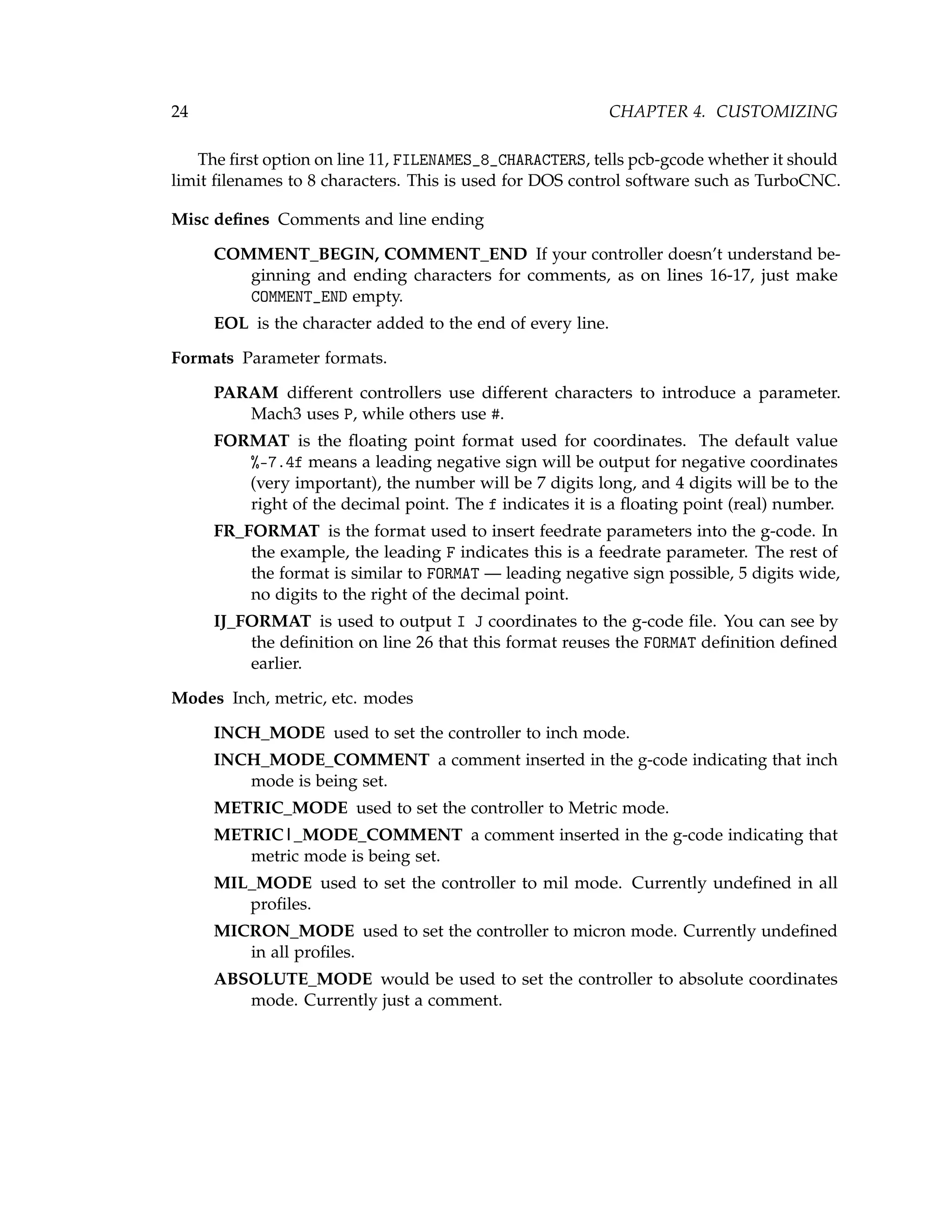
Compact gcode eliminates some redundant commands in the g-code file, such as
having G01 on every line.
Use line numbers? inserts line numbers into the g-code file. The format shown
%05d will insert 5 digit numbers with leading zeroes.
Use simple drill code uses XYZ movements to create drill holes. Usually DRILL_FIRST_HOLE
and DRILL_HOLE are used, but some controllers don’t understand the command
(typically G82).
File naming every option one could want for naming files.
Macros the following can be used in the file name to create the final file name. Note
that paths do not include a / at the end. Also note that / is always the path
delimiter, even on Windows. Eagle handles the conversion automatically.
$PROJECT_PATH[n] Project paths as set in the Eagle Control Panel. n begins
at zero for the first entry.
$ULP_PATH[n] ULP paths as set in the Control Panel.
$CAM_PATH[n] CAM paths as set in the Control Panel.
$BOARD_PATH path to the board file.
$BOARD_NAME the file name of the board file with the extension removed.
$SIDE the side of the board being generated. Defaults are ’bot’ and ’top’.
$FILE the file being generated. Defaults are ’etch’, ’drill’, ’mill’ and ’text’.
$EXT the extension set in Extension on this screen.
Test Filenames click the button to see how the file names will look.
Help gives a list of the macros defined above and tips on creating file names.
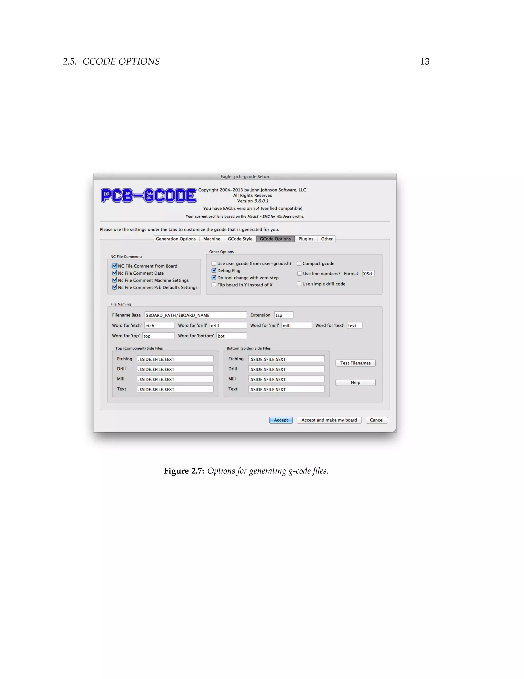
Using the options shown in 2.7, here is how the filename for the top etching file will
be created:
• The board path and board name will be used. (Filename Base)
• The word for ’top’ will be substituted for $SIDE. (See Etching under Top (Component)
Side Files.
• The word for ’etch’ will be substituted for $FILE.
• The Extension will be substituted for $EXT.
Using examples for the board path and name, the final file name would be:
/Users/john/Documents/pcbcode/examples/enabtmr.top.etch.tap](https://image.slidesharecdn.com/pcbgcode-200426162959/75/Pcbgcode-22-2048.jpg)


![4.4. USER GCODE 29
8 43 43 wire gage drill
4.4 User GCode
!
Advanced
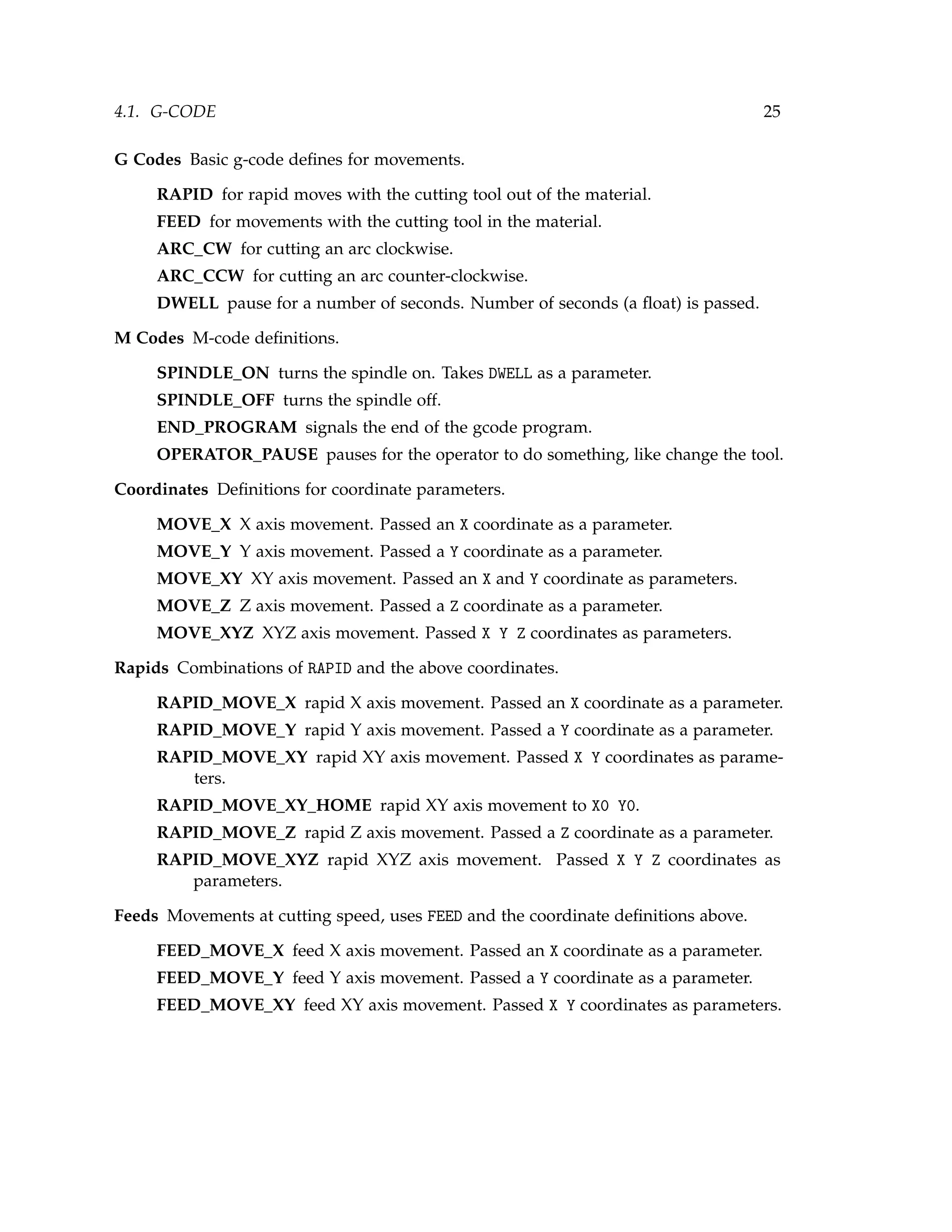
The pcbâ´LŠgcode ULP allows you to customize the gâ´LŠcode created for your boards to a
great degree. If you don’t see an option in the profile that suits your needs, you can add
your code to the user-gcode.h file. To enable user g-code, run pcb-gcode-setup, click
the GCode Options tab, then turn the Use user gcode... option on. Generate a set of
NC files for a board. Let’s say, for example, that after you change the tool when you’re
drilling from the bottom of the board, you want the tool to move to X5 Y5 Z5, turn the
spindle off, then turn it back on. Since this has to do with drilling the bottom of the board,
we should look at the ...bot.drill.tap (bottom drill) file. An excerpt from a file is shown in
Listing 4.3.
Listing 4.3: Bottom drill file before adding user g-code.
1 G90
2 (Tool Change Begin)
3 (Bottom Tool Change Begin)
4 M05
5 G00 X0 .0000 Y0 .0000 Z2 .0000
6 M06 T01 ; 0.0236
7 (Bottom Tool changed)
8 (Tool changed)
9 G00 Z0 .0200
10 M03
11 G04 P3 .000000
12 (Bottom Tool Change End)
13 (Tool Change End)
14 G82 XâĹŠ1 .6200 Y1 .2900 ZâĹŠ0 .1000 F9.80 R0 .0200 P0 .250000
15 G82 XâĹŠ1 .8800 Y0 .5900
16 G82 XâĹŠ1 .9500 Y1 .4900
17 G82 XâĹŠ1 .9500 Y1 .8100
We want to add our commands after the tool is changed when drilling the bottom of
the board. Looking at the sample above, you will find this line:
12 (Bottom Tool Change End)
That’s where we want our code to go. Now you can open user-gcode.h in your favorite
editor, and use the Search or Find feature to find the line with Bottom Tool Change End.
Here’s an excerpt from the userâ´LŠgcode.h file:
1 TOOL_ZERO_BEGIN[BOTTOM] = "(Bottom Tool zero begin)n";
2 TOOL_ZERO_END[BOTTOM] = "(Bottom Tool zero end)n";
3 TOOL_CHANGE_END[BOTTOM] = "(Bottom Tool Change End)n";](https://image.slidesharecdn.com/pcbgcode-200426162959/75/Pcbgcode-37-2048.jpg)
![30 CHAPTER 4. CUSTOMIZING
4 TOOL_CHANGE_BEGIN [TOP] = "(Top Tool Change Begin)n";
The 3rd line is the one we’re interested in:
3 TOOL_CHANGE_END [BOTTOM] = "(Bottom Tool Change End)n";
Change the line so that it looks like this:
3 TOOL_CHANGE_END [BOTTOM] = "(Bottom Tool Change End)n"
4 "G00 X5 Y5 Z5n"
5 "M05 (spindle off)n"
6 "G04 P3 .000000 (wait 3 seconds)n"
7 "M03 (spindle on)n";
8 "G04 P3 .000000 (wait 3 more secondsn";
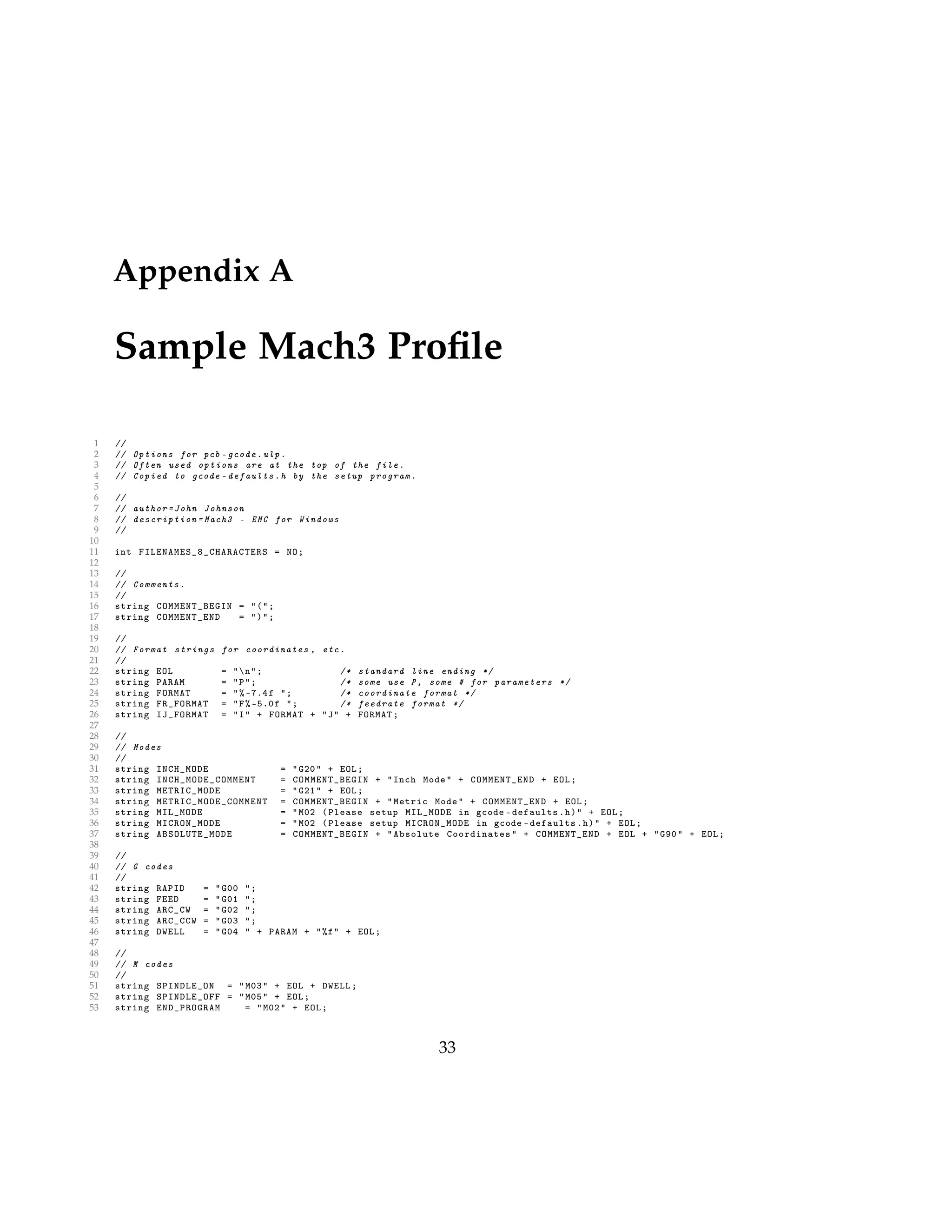
Notice that all the lines have a n before the last " and that the last line is the only one
that ends with a semiâ´LŠcolon ;. Generate the files again. Open the bottom drill file in
the editor and have a look. Here’s how the sample looks now:
1 G90
2 (Tool Change Begin)
3 (Bottom Tool Change Begin)
4 M05
5 G00 X0 .0000 Y0 .0000 Z2 .0000
6 M06 T01 ; 0.0236
7 (Bottom Tool changed)
8 (Tool changed)
9 G00 Z0 .0200
10 M03
11 G04 P3 .000000
12 (Bottom Tool Change End)
13 G00 X5 Y5 Z5
14 M05 (spindle off)
15 G04 P3 .000000 (wait 3 seconds)
16 M03 (spindle on)
17 G04 P3 .000000 (wait 3 more seconds)
18 (Tool Change End)
19 G82 XâĹŠ1 .6200 Y1 .2900 ZâĹŠ0 .1000 F9.80 R0 .0200 P0 .250000
20 G82 XâĹŠ1 .8800 Y0 .5900
21 G82 XâĹŠ1 .9500 Y1 .4900
22 G82 XâĹŠ1 .9500 Y1 .8100
Note that the lines added to the user-gcode.h file are now in the generated g-code from
lines 13-17.
Since we put our code in the TOOL_CHANGE_END[BOTTOM] definition, it will only be put
in files for the bottom side of the board. So the code will be in the bot.drill file. If we only
wanted our code in files for the top side, we would have put the code in TOOL_CHANGE_END
[TOP]. You can probably guess that if we wanted the code in both the top and bottom](https://image.slidesharecdn.com/pcbgcode-200426162959/75/Pcbgcode-38-2048.jpg)
![4.4. USER GCODE 31
files, we would have put the code in TOOL_CHANGE_END[TOOL_CHANGE_END[ALL]. To conclude,
the steps to follow are:
1. Generate a set of files.
2. Find the file that you want the code to be put in (bot, top, etc.).
3. Find the location in the file that you want the code.
4. Find the comment near that location.
5. Find the comment in the userâ´LŠgcode.h file.
6. Insert your code after the comment.
7. Generate the files again and check to be sure it is correct.](https://image.slidesharecdn.com/pcbgcode-200426162959/75/Pcbgcode-39-2048.jpg)


This document provides information about setting up and using PCB-GCODE, a program for generating G-CODE files from EAGLE PCB designs to cut circuit boards using a CNC machine. It discusses downloading and installing PCB-GCODE, selecting options for board generation and G-CODE styles, using previews and customization features, and providing support for users. The document contains various figures and tables to illustrate concepts and settings.
![Cimco edit 5 user guide[1]](https://cdn.slidesharecdn.com/ss_thumbnails/cimcoedit5userguide1-110305112440-phpapp01-thumbnail.jpg?width=640&height=640&fit=bounds)