Download to read offline


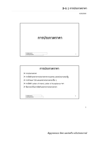
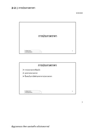


ภาคที่ 2: ภาคปฎิบัติ ในส่วนนี้จะอธิบายถึงวิธีการจัดทำเอกสารประกวดราคาสัญญาออกแบบ จัดหา และก่อสร้าง 2-1 การประกวดราคา เอกสารชุดนี้ จัดทำขึ้นเพื่อประกอบการบรรยายเรื่องการประกวดราคา สำหรับการอบรม นักกฎหมายก่อสร้าง รุ่นที่ 2 จัดโดยชมรมนักกฎหมายก่อสร้างเมื่อวันที่ 15 สิงหาคม 2563 2-2 คู่มือการจัดเตรียมเอกสารประกวดราคา เอกสารชุดนี้ จัดทำขึ้นเพื่อประกอบการบรรยายเรื่อง การจัดเตรียมเอกสารประกวดราคา แก่บริษัท บริษัท โปรเจค แพลนนิ่ง เซอร์วิส จำกัด (มหาชน) เมื่อปี พ.ศ. 2561 และเอกสารประกอบการบรรยายเรื่อง “การจัดทำรายการประกอบแบบก่อสร้าง (Specifications)” ISA โครงการพัฒนาวิชาชีพ ครั้งที่ 3 จัดโดยสมาคมสถาปนิกสยามแห่งประเทศไทยในพระบรมราชูปถัมภ์ เมื่อวันที่ 6 กันยายน 2551


