
Download to read offline


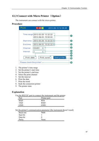
![V
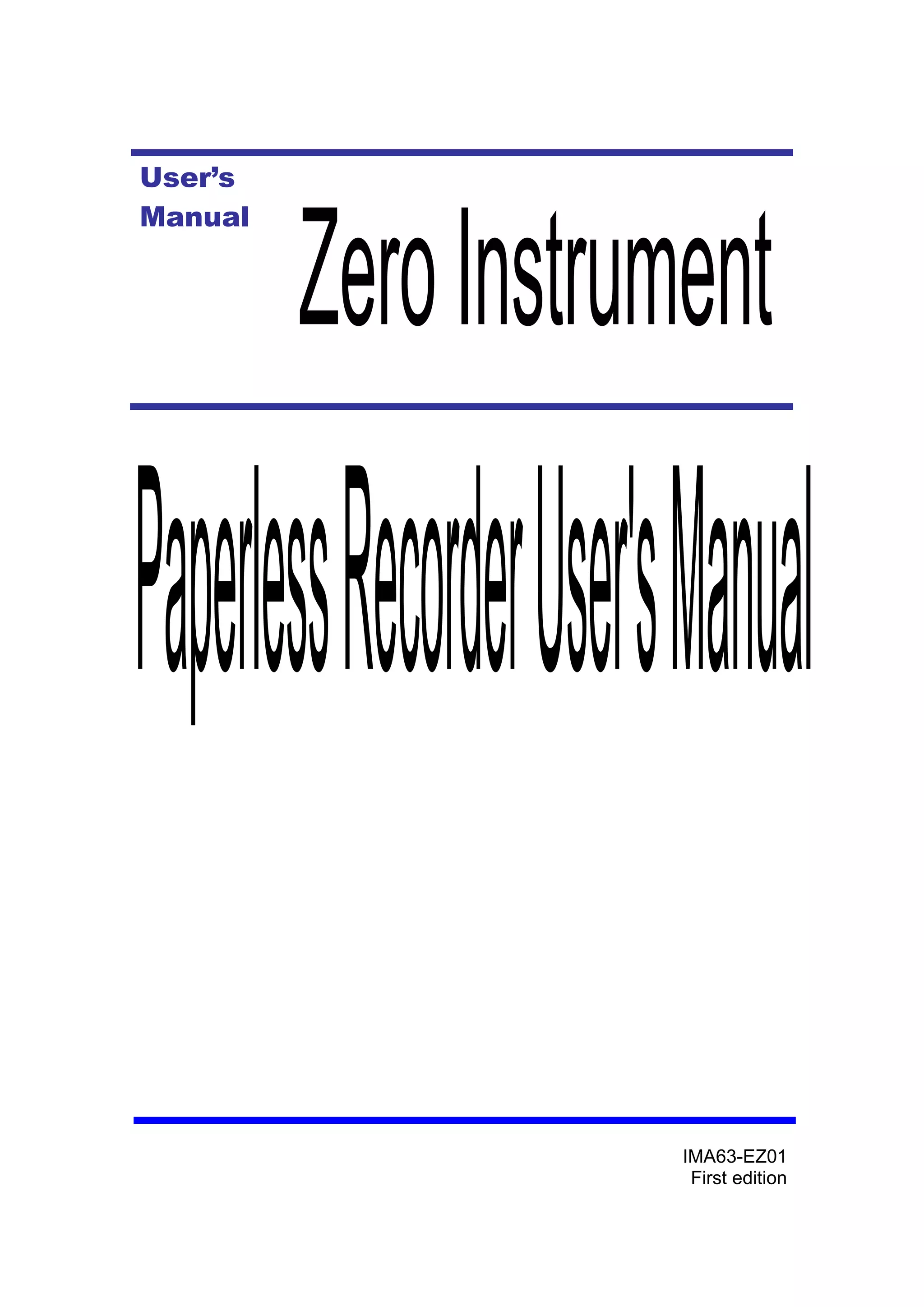
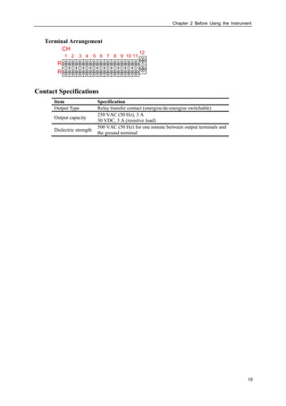
Conventions Used in this Manual
1. Unit
K Denotes”1024”
k Denotes”1000”
M Denotes“1024K”
G Denotes“1024M”
B “Bytes”
2. Symbols (The following symbols are used in this manual)
WARNING Describes precautions that should be observed to prevent
injury or death to the user.
CAUTION Describes precautions that should be observed to prevent
damage to the instrument.
Note Provides important information for the proper operation of the
instrument.
3. Notation regarding procedures
The following symbols are used during the explanation of operation
[ ] ............ Represent key’s name. Example: [Page] [En]
『』 ….... Indicate a reference item. Example: 『Input Channel Setting』](https://image.slidesharecdn.com/paperlessrecorderusermanual-180305083513/85/Paperless-recorder-user-manual-7-320.jpg)


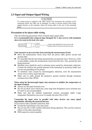
![Chapter 2 Before Using the Instrument
25
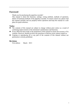
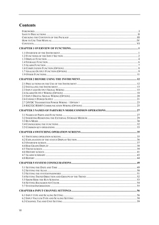
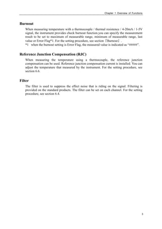
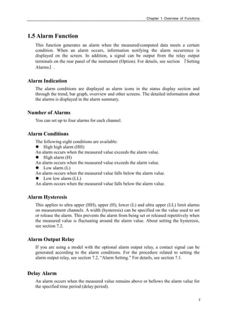
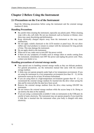
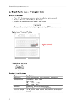
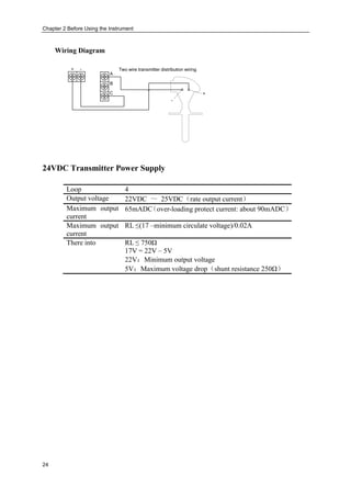
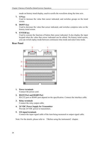
2.8 RS232C/RS485 Communication Wiring (Option)
Wiring Procedure
RS232 Communication wiring position
1 2 3 4 5
9876
Communication
connection
Pin number Signal Name Description
2 RXD instrument receive data
3 TXD instrument send data
5 GND Signal Ground
7 485A RS485 communication wiring +
8 485B RS485 communication wiring -
RS232C Wiring
RXD[incept data]
PC InstrumentTXD[send data]
GND[signal ground wire]
Signal direction](https://image.slidesharecdn.com/paperlessrecorderusermanual-180305083513/85/Paperless-recorder-user-manual-35-320.jpg)
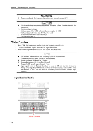
![Chapter 3 Names of Parts/Run Mode/Common Operations
30
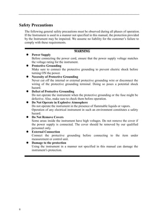
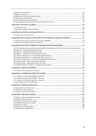
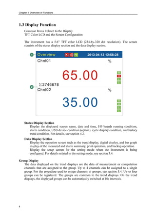
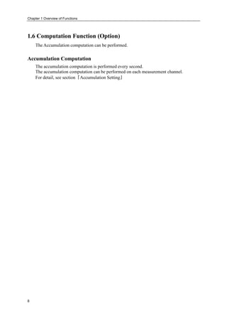
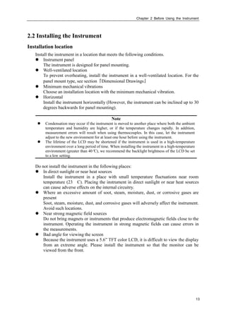
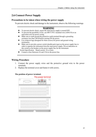
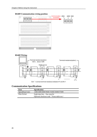
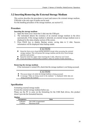
3.3 Run Mode
There are two run modes: operating and setting. This section describes the functions and
relationships of the two modes.
Mode Types
Operation
screens
Setting
screens
Menu screen
Pressing
[Page]+[Enter]for
1 second
Exit menu
->[Enter]
Sofe menu
->[Enter]
Exit menu
->[Enter]
Power ON
Opration mode
Setting
Mode Type Description Possible operations
Operation
Mode
This mode is used for daily operation.
This mode is entered when the power is turned
ON.
Back up data to the external storage.
Monitoring operation
Data acquisition
Data printing
Operation related to the file
on the external storage
medium.
Setting Mode This mode is used to configure the operation
such as input range and alarms.
This mode is entered by pressing the [Page] and
[Enter] key for one second at the setting mode
menu.
Measured data can’t be displayed in this mode.
Operations such as measurements, alarm
detection, and data acquisition are continued.
Settings of the functions.](https://image.slidesharecdn.com/paperlessrecorderusermanual-180305083513/85/Paperless-recorder-user-manual-40-320.jpg)
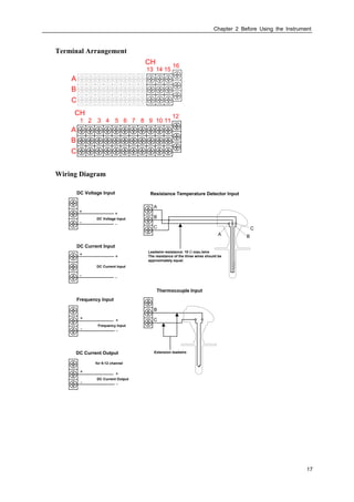
![Chapter 3 Names of Parts/Run Mode/Common Operations
31
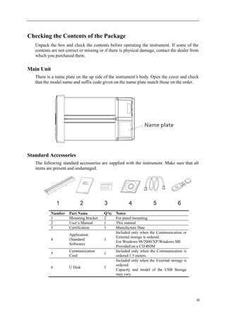
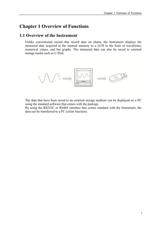
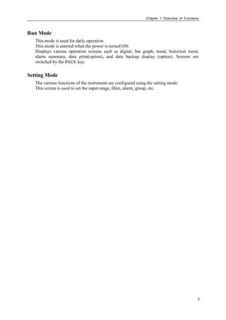
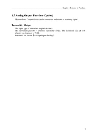
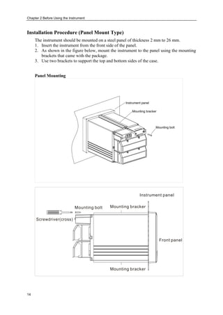
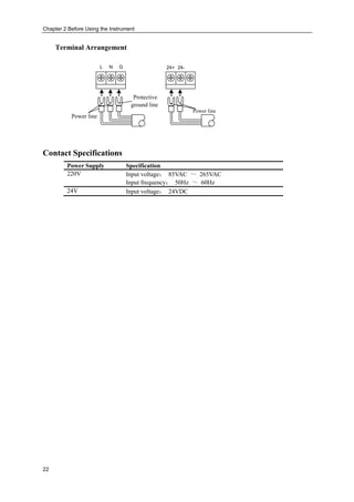
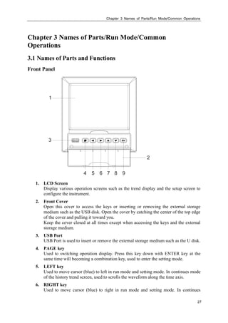
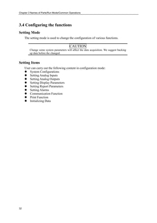
Functions and Operations in the Operation Mode
Operation screen
Display various operation screens such as digital, trend, bar graph, historical trend, alarm
summary, print and back up.
Screens are switched by the [Page] key. See section 4.1.
The operation screen with different key operating has the different functions. The
concrete pressed key operation and the function please see section 4.1.
Functions of setting modes
Use arrow keys and [En] key to set the instrument’s functions.
See sections 5.1 to 12.4.](https://image.slidesharecdn.com/paperlessrecorderusermanual-180305083513/85/Paperless-recorder-user-manual-41-320.jpg)
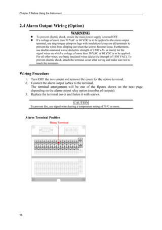
![Chapter 3 Names of Parts/Run Mode/Common Operations
33
3.5 Common key operations
This section describes common key operations which are used often.
Key operations in the setting mode
Entering the setting mode
1. Power on immediacy enter the setting mode
2. Select [Exit] to enter the setting mode in the configuration mode.
Switching the screens under the setting mode
Press [Page] to display each setting screen in turn.
Key operations in the configuration mode
Entering the configuration mode
1. Under the setting mode, Press [Page] and [En] to enter the configuration screen.
2. Move the cursor and press the [En] to enter each configuration screen.
Selecting the parameter
Used [Left] and [Right] to move the cursor (blue) to the appropriate parameter or
operation key.
Confirming operation
Press [En] to confirm the settings.
Modifying the parameter
There are two types of the revisable parameters, select input parameter and edit input
parameter.
Selecting input parameter(The right of the input frame has the sign )
Used [Up] and [Down] to move the cursor to modify the appropriate parameter.
Edit input parameter(The right of the input frame has no sign)
When the parameter can be edited, user can input Number, English (Caps), English,
Symbol and Chinese.
Move the cursor to the edited parameter, press [En] to the input panel, user can do it.](https://image.slidesharecdn.com/paperlessrecorderusermanual-180305083513/85/Paperless-recorder-user-manual-43-320.jpg)
![Chapter 3 Names of Parts/Run Mode/Common Operations
34
Input Number/English (Caps)/English/Symbol
Used in inputting range, unit, tag etc.
Procedure
[Left][Right]:Move the cursor to the soft key or input method.
[Up][Down]:Move the cursor of the soft key.
[Page]:Switch the cursor’s area.(Soft key /Input method)。
[En]: Input the character to the input field, which under the place of cursor.
Cursor at [Delete]:Delete the last character in the input field.
Cursor at [Cancel]:Exit the input panel, cancel the editing.
Cursor at [Enter]: Exit the input panel, confirm the editing.
If the cursor at the input method area, you can switch it to the soft key area.](https://image.slidesharecdn.com/paperlessrecorderusermanual-180305083513/85/Paperless-recorder-user-manual-44-320.jpg)
![Chapter 4 Switching Operation Screens
35
Chapter 4 Switching Operation Screens
4.1 Switching operation screens
This chapter describes the screen (operation screen) used to display the measured /
computed data.
The operation screens are composed of Overview, Bar, Trend, History, Alarm summary,
Print (Add-ones function) and Backup (Add-ones function).
Used the [Page] key can switch each screen.
Overview
screen
Bar
screen
Trend
screen
History
screen
Alarm
summary
screen
Print Screen
(Add-ones
function)
Power on
Backup Screen
(Add-ones
function)](https://image.slidesharecdn.com/paperlessrecorderusermanual-180305083513/85/Paperless-recorder-user-manual-45-320.jpg)
![Chapter 4 Switching Operation Screens
36
4.2 Explanation of the status Display Section
The following information is displayed in the status display section during the operation
mode and the configuration mode.
1. Screen name
Displayed the screen name, [Alias] is displayed during all channel display.
2. Board card status flag
None Work normal
A All Interior boards don’t work
B The board in Socket1 doesn’t work
C The board in Socket2 doesn’t work
Note
When the instrument displayed this flag, there was something wrong with it,
you should contact the Supplier.
3. Alarm status flag
Alarm icon: Relay exports the alarm.
None: Relay doesn’t export the alarm.
4. USB Equipment flag
5. Circulation display flag (Trend screen)
Circulation icon: Circulation Display each group
None: Fixed screen, don’t circulation.
6. History trend status flag (History screen)
None Not in this screen
D Continuous state
E Fixed point state
7. Current data and time](https://image.slidesharecdn.com/paperlessrecorderusermanual-180305083513/85/Paperless-recorder-user-manual-46-320.jpg)
![Chapter 4 Switching Operation Screens
37
4.3 Overview screen
1. Channel tag. See section『Channel Tag and Unit Setting』
2. Engineering value. Blue is Normal, red is alarming
Note
Measure the channel’s data display
When measuring data of measurement channel anomalies (see below), the
screen shows measurements for #####.
Data exception
4-20 mA : signal bellows 2 mA.
The thermocouple burnout , the [burnout set] display #####.
3. Channel accumulation value.
4. Channel unit. See section『Channel Tag and Unit Setting』
5. Alarm symbol. From up to down, high high alarm, high alarm, low alarm, low low
alarm. Green is normal, red is alarm.](https://image.slidesharecdn.com/paperlessrecorderusermanual-180305083513/85/Paperless-recorder-user-manual-47-320.jpg)
![Chapter 4 Switching Operation Screens
38
4.4 Bar Graph Display
1. Channel tag. See section『Channel Tag and Unit Setting』
2. Bar. Bar chart ruler has the length of 10 grids, and the length of filling color
represents proportion in percent. Green is normal, red is alarm.
3. Channel unit. See section『Channel Tag and Unit Setting』
4. Engineering value .Blue is normal, red is alarm.
Note
Measure the channel’s data display
When measuring data of measurement channel anomalies (see below), the
screen shows measurements for #####.
Data exception
4-20 mA : signal bellows 2 mA.
The thermocouple burnout , the [burnout set] display #####.
5. Alarm symbol. From up to down, high high alarm, high alarm, low alarm, low low
alarm. Green is normal, red is alarm. Indications of each channel’s alarm state.](https://image.slidesharecdn.com/paperlessrecorderusermanual-180305083513/85/Paperless-recorder-user-manual-48-320.jpg)
![Chapter 4 Switching Operation Screens
40
Note
Measure the channel’s data display
When measuring data of measurement channel anomalies (see below), the
screen shows measurements for #####.
Data exception
4-20 mA : signal bellows 2 mA.
The thermocouple burnout , the [burnout set] display #####.
9. Alarm symbol. From up to down, high high alarm, high alarm, low alarm, low low
alarm. Green is normal, red is alarm. Indications of each channel’s alarm state.
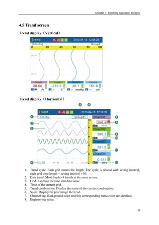
10. Channel unit. See the section of『Channel Tag and Unit Setting』
11. Trend sequence number
12. Trend display symbol. “√” display, “×” hide.
Trends refurbish
On time axis of the instrument’s LCD screen, every pixel stands for a record interval.
Every record interval in trend moves once.
Group circulation
When started the circulation display function, switched to next group display trend for
every 10 seconds.
Procedure
Switch trend display group
[Up] is used to switch to next effectual group display trend.
Circular display the trend display group
[En] is used to open or close display with circulation. When open this function, there will
be an icon appeared in the state bar. See section『Explanation of the status Display
Section』.
Display or hide a trend
Move the cursor (black) with [Left] and [Right] keys, pitch on the channel needing
display or hide a trend, press [Down] to hide or display the trend.](https://image.slidesharecdn.com/paperlessrecorderusermanual-180305083513/85/Paperless-recorder-user-manual-50-320.jpg)
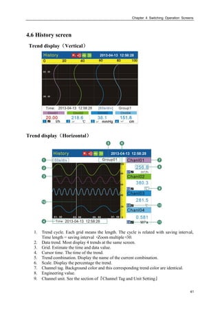
![Chapter 4 Switching Operation Screens
42
10. Trend sequence number
11. Trend display symbol. “√” display, “×” hide.
Procedure
There exist two methods to search historical data. One is continuous and the other is
fixed point.
The current state tag, please see section of『Explanation of the status Display Section』.
Switch the continuous state and the fixed point state
Under the continuous state, press [En] to switch to the fixed point state.
Under the fixed point state, press [En] to switch to the continuous state.
Continuous state
Switch channel trend
Within this state, uses [up] to display the next channel’s trend.
Trend zoom
Under the continuous state, press [Down] to switch the trend zoom times, circulation
switch between 1 times/ 2 times/ 4 times/ 8 times/ 16 times/ 32 times.
Operation
Uses [Left] and [Right] to move cursor so that forward or backward searching is
available.
The trend moves 1/3 screen trend voluntarily when the trend cursor remove arrives at
screen border.
Fixed point state
Display or hide the trend
Within this state, uses [Left] and [Right] to move cursor (Black) and chooses the
trend in channel to be displayed or hided by pressing [Down].
Operation
Uses [Left] and [Right] to move cursor. Set the data time to a desired point by using
[Up] and [Down]. Press [En], the trend will be moved to the fixed point
automatically.](https://image.slidesharecdn.com/paperlessrecorderusermanual-180305083513/85/Paperless-recorder-user-manual-52-320.jpg)
![Chapter 4 Switching Operation Screens
44
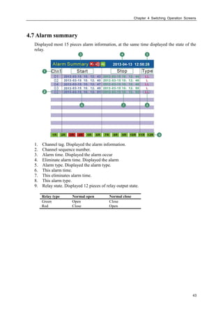
4.8 Report
There are four types of cumulative report (Hourly, 8Hourly, 12Hourly, Daily, Monthly)
Report-Hourly
Report-Hourly 2013-04-13 14:11:26
2013-04-12Date: Chnl: PrintChnl01
∑3.69 Daily Sum : 0.00
01: 09: 17:
02: 10: 18:
03: 11: 19:
04: 12: 20:
05: 13: 21:
06: 14: 22:
07: 15: 23:
08: 16: 00:
0.00 0.00 0.00
0.00 0.00 0.00
0.00 0.00 0.00
0.00 0.00 0.00
0.00 0.00 0.00
0.00 0.00 0.00
0.00 0.00 0.00
0.00 0.00 0.00
1. Query
Query report by setting the date, uses [Left] or [Right] key to move the cursor, Press
[Up] or [Down] key to configure the time .The report displays 24 hours’
accumulation values on the screen.
2. Channel selection
Move the cursor to the edit box of channel, Press [Up] or [Down] key to select the
channel.
3. Print
Move the cursor to the button named “Print”, press [En] to print the report of current
screen.](https://image.slidesharecdn.com/paperlessrecorderusermanual-180305083513/85/Paperless-recorder-user-manual-54-320.jpg)
![Chapter 4 Switching Operation Screens
45
Report-8Hourly
Report-8Hourly 2013-04-13 14:11:26
2013-04-12Date: Chnl: PrintChnl01
∑3.69
04-12:
04-13:
04-14:
04-15:
04-16:
04-17:
04-18:
04-19:
0.00 0.00 0.00
0.00 0.00 0.00
0.00 0.00 0.00
0.00 0.00 0.00
0.00 0.00 0.00
0.00 0.00 0.00
0.00 0.00 0.00
0.00 0.00 0.00
1. Query
Query report by setting the date, uses [Left] or [Right] key to move the cursor, Press
[Up] or [Down] key to configure the time. Display the data of 7 days since the date
of the settlement, 3 cumulative values for each day.
2. Channel selection
Move the cursor to the edit box of channel, Press [Up] or [Down] key to select the
channel.
3. Print
Move the cursor to the button named “Print”, press [En] to print the report of current
screen.](https://image.slidesharecdn.com/paperlessrecorderusermanual-180305083513/85/Paperless-recorder-user-manual-55-320.jpg)
![Chapter 4 Switching Operation Screens
46
Report-12Hourly
Report-12Hourly 2013-04-13 14:11:26
2013-04-12Date: Chnl: PrintChnl01
∑3.69
04-12:
04-13:
04-14:
04-15:
04-16:
04-17:
04-18:
04-19:
0.00 0.00
0.00 0.00
0.00 0.00
0.00 0.00
0.00 0.00
0.00 0.00
0.00 0.00
0.00 0.00
1. Query
Query report by setting the date, uses [Left] or [Right] key to move the cursor, Press
[Up] or [Down] key to configure the time. Display the data of 7 days since the date
of the settlement, 2 cumulative values for each day.
2. Channel selection
Move the cursor to the edit box of channel, Press [Up] or [Down] key to select the
channel.
3. Print
Move the cursor to the button named “Print”, press [En] to print the report of current
screen.](https://image.slidesharecdn.com/paperlessrecorderusermanual-180305083513/85/Paperless-recorder-user-manual-56-320.jpg)
![Chapter 4 Switching Operation Screens
47
Report-Daily
Report-Daily 2013-04-13 14:11:26
2013-03Date:
Chnl:
Print
Chnl01
∑3.69
01: 12: 23:
02: 13: 24:
03: 14: 25:
04: 15: 26:
05: 16: 27:
06: 17: 28:
07: 18: 29:
08: 19: 30:
09: 20: 31:
10: 21:
11: 22:
0.00 0.00 0.00
0.00 0.00 0.00
0.00 0.00 0.00
0.00 0.00 0.00
0.00 0.00 0.00
0.00 0.00 0.00
0.00 0.00 0.00
0.00 0.00 0.00
0.00 0.00 0.00
0.00 0.00
0.00 0.00
Monthly
Mon Sum: 0.00
Average: 0.00
Maximum: 0.00
Minimum: 0.00
1. Query
Query report by setting the date, uses [Left] or [Right] key to move the cursor, Press
[Up] or [Down] key to configure the time. Display the data of 7 days since the date
of the settlement, 2 cumulative values for each day.
2. Channel selection
Move the cursor to the edit box of channel, Press [Up] or [Down] key to select the
channel.
3. Print
Move the cursor to the button named “Print”, press [En] to print the report of current
screen.
4. Report –Monthly
Move the cursor to the button named “Monthly”, press [En] to display monthly
report.
5. Stat.
Display the value of month sum, average, maximum and minimum](https://image.slidesharecdn.com/paperlessrecorderusermanual-180305083513/85/Paperless-recorder-user-manual-57-320.jpg)
![Chapter 4 Switching Operation Screens
48
Report-Monthly
Report-Monthly 2013-04-13 14:11:26
Print
Annual Sum: 0.00
∑3.69
2012-04: 2012-11:
2012-05: 2012-12:
2012-06: 2013-01:
2012-07: 2013-02:
2012-08: 2013-03:
2012-09: 2013-04:
2012-10:
0.00 0.00
0.00 0.00
0.00 0.00
0.00 0.00
0.00 0.00
0.00 0.00
0.00
Exit
1. Display cumulative value of 13 months before current month
2. Move the cursor to the [Print] key, press the [En] key to print the current screen.
3. Move the cursor to the [Exit] key, press the [En] key back to the screen of
Report-Daily.](https://image.slidesharecdn.com/paperlessrecorderusermanual-180305083513/85/Paperless-recorder-user-manual-58-320.jpg)
![Chapter 5 System Configurations
49
Chapter 5 System Configurations
5.1 Setting the Date and Time
Procedure
Press [Page] and [En] at the same time, enter the configuration menu.
Use arrow keys and [En] to input the password, enter the [System] screen.
Confirming operation
After the parameter setting, select [Exit] there is a Frame.
Select [Yes] to save setting content, and exit [System] screen.
Select [No] to cancel setting content, and exit [System] screen.
Select [Cancel] to continue setting parameters in [System] screen.
Caution
After setting system date / time, those historical data stored in
instrument is invalid.
New and effective data begins after setting system date / time.
Before setting system date / time, please backup history data.](https://image.slidesharecdn.com/paperlessrecorderusermanual-180305083513/85/Paperless-recorder-user-manual-59-320.jpg)
![Chapter 5 System Configurations
50
5.2 Setting the Alias
Procedure
Press [Page] and [En] at the same time, enter the configuration menu.
Use arrow keys and [En] to input the password, enter the [System] screen.
About the input method of editing parameter, see section『Common key operations』
Confirming operation
After the parameter setting, select [Exit] there is a Frame.
Select [Yes] to save setting content, and exit [System] screen.
Select [No] to cancel setting content, and exit [System] screen.
Select [Cancel] to continue setting parameters in [System] screen.](https://image.slidesharecdn.com/paperlessrecorderusermanual-180305083513/85/Paperless-recorder-user-manual-60-320.jpg)
![Chapter 5 System Configurations
51
5.3 Setting the system password
System password is needed when modifies configuration parameters, and is used to
prevent system parameters from being changed by accident.
It is made by 6 numbers.
Procedure
Press [Page] and [En] at the same time, enter the configuration menu.
Use arrow keys and [En] to input the password, enter the [System] screen.
About the input method of editing parameter, see section『Common key operations』
Confirming operation
After the parameter setting, select [Exit] there is a Frame.
Select [Yes] to save setting content, and exit [System] screen.
Select [No] to cancel setting content, and exit [System] screen.
Select [Cancel] to continue setting parameters in [System] screen.
Note
It is a unique password to modify configuration parameters. Once it is
forgotten, it can not be modified those parameters.
The initial password is 000000, after purchasing instrument, it is better
for users to amend it as soon as possible and preserve it properly.](https://image.slidesharecdn.com/paperlessrecorderusermanual-180305083513/85/Paperless-recorder-user-manual-61-320.jpg)
![Chapter 5 System Configurations
52
5.4 Setting Trend Direction and Groups of the Trend
User can choose two directions of trends, horizontal and vertical. When the horizontal,
the trend is from right to left; when vertical, it’s from up to down.
User can set four trend groups and enable it to use. Each trend is composed of 1-4 trends,
has 4 kind of different trend colors.
Procedure
Press [Page] and [En] at the same time, enter the configuration menu.
Use arrow keys and [En] to input the password, enter the [Display] screen.
1. Set the trend direction
Press arrow keys to choose the trend direction, horizontal or vertical. It’s usable for
Trend and History.
2. Select the trend group
Press arrow keys to choose trend group.
3. Enable the trend group to use or no
Move the cursor to [Enable], and use the arrow keys to set the trend group.
4. Set the channel of current trend
User can input channels at discretion, there are four colors for the trend in right side.
Confirming operation
After the parameter setting, select [Exit] there is a Frame.
Select [Yes] to save setting content, and exit [Display] screen.
Select [No] to cancel setting content, and exit [Display] screen.
Select [Cancel] to continue setting parameters in [Display] screen.](https://image.slidesharecdn.com/paperlessrecorderusermanual-180305083513/85/Paperless-recorder-user-manual-62-320.jpg)
![Chapter 5 System Configurations
53
5.5 Show/Hide the Run Screens
Procedure
Press [Page] and [En] at the same time, enter the configuration menu.
Use arrow keys and [En] to input the password, enter the [Display] screen.
Press arrow keys to show or hide the relevant screens.
Confirming operation
After the parameter setting, select [Exit] there is a Frame.
Select [Yes] to save setting content, and exit [Display] screen.
Select [No] to cancel setting content, and exit [Display] screen.
Select [Cancel] to continue setting parameters in [Display] screen.](https://image.slidesharecdn.com/paperlessrecorderusermanual-180305083513/85/Paperless-recorder-user-manual-63-320.jpg)
![Chapter 5 System Configurations
54
5.6 Setting Background Color
User can choose background color for the screen of overview and bar .
Procedure
Press [Page] and [En] at the same time, enter the configuration menu.
Use arrow keys and [En] to input the password, enter the [Display] screen.
Set background color
Display 2013-04-13 13:21:32
Exit
Direction: Horizontal
Group: Group1 Enable: Yes
Trend 1: Chnl1 Color:
Trend 2: Chnl2 Color:
Trend 3: Chnl3 Color:
Trend 4: Chnl4 Color:
Overview√ Bar √ Trend √
History √ Alarm √ Print √
Backup √
Background Color: White
Setting Background Color
Press arrow keys to choose white or black color for the background of overview and
bar screens
Confirming operation
After the parameter setting, select [Exit] there is a Frame.
Select [Yes] to save setting content, and exit [Display] screen.
Select [No] to cancel setting content, and exit [Display] screen.
Select [Cancel] to continue setting parameters in [Display] screen.](https://image.slidesharecdn.com/paperlessrecorderusermanual-180305083513/85/Paperless-recorder-user-manual-64-320.jpg)
![Chapter 5 System Configurations
55
5.7 System Information
Procedure
Press [Page] and [En] to enter configuration menu.
Use arrow keys and [En] to input the password, enter the [About] screen.
Explanation
1. The Option Functions
2. The number and type of the hardware in-out channels.
3. The output loop of the relay
4. The Firmware issue date and version number
5. [Exit] soft key](https://image.slidesharecdn.com/paperlessrecorderusermanual-180305083513/85/Paperless-recorder-user-manual-65-320.jpg)
![Chapter 6 Input Channel Settings
56
Chapter 6 Input Channel Settings
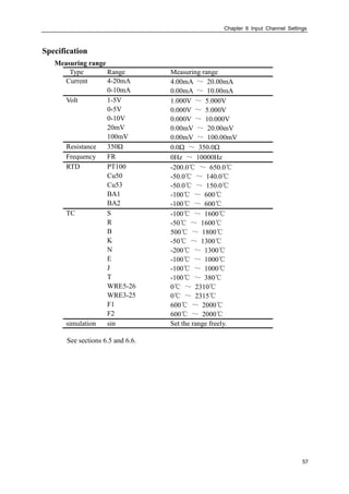
6.1 Input type and Scaling Setting
Procedure
Press [Page] and [En] at the same time, enter the configuration menu.
Use arrow keys and [En] to input the password, enter the [Input] screen.
1. Input channel
Select the channel to set the parameter, which is limited of the input board channel’s
number.
2. Channel type
Set the current channel’s input signal type.
3. Channel range
Set the current channel's input signal measuring range.
4. Adjust value
Set the correct value,Display data=Measure data ×K + B。
Note
The high and low value should not be the same.
The low value is -9999 and high range is 19999.
Confirming operation
After the parameter setting, select [Exit] there is a Frame.
Select [Yes] to save setting content, and exit [Input] screen.
Select [No] to cancel setting content, and exit [Input] screen.
Select [Cancel] to continue setting parameters in [Input] screen.](https://image.slidesharecdn.com/paperlessrecorderusermanual-180305083513/85/Paperless-recorder-user-manual-66-320.jpg)
![Chapter 6 Input Channel Settings
58
6.2 Input Vacuum Type and Scaling Setting
Procedure
Press [Page] and [En] at the same time, enter the configuration menu.
Use arrow keys and [En] to input the password, enter the [Input] screen.
1. Input channel
Select the channel to set the parameter, which is limited of the input board channel’s
number.
2. Channel type
Set the current channel’s input signal type.
3. Channel range
Set the current channel's input signal measuring range.
4. Set vacuum type
There are two vacuum types, normal arithmetic and subsection arithmetic. User can
choose it base on vacuum transmitter signal.
5. Adjust value
When the measuring mode is vacuum measure, the adjust value will be invalidated.
Note
The high and low value should not be the same.
The low value is -9999 and high range is 19999. You can only change the
index.
Confirming operation
After the parameter setting, select [Exit] there is a Frame.
Select [Yes] to save setting content, and exit [Input] screen.
Select [No] to cancel setting content, and exit [Input] screen.
Select [Cancel] to continue setting parameters in [Input] screen.](https://image.slidesharecdn.com/paperlessrecorderusermanual-180305083513/85/Paperless-recorder-user-manual-68-320.jpg)
![Chapter 6 Input Channel Settings
59
6.3 Channel Tag and Unit Setting
Procedure
Press [Page] and [En] at the same time, enter the configuration menu.
Use arrow keys and [En] to input the password, enter the [Input] screen.
1. Channel tag
Press [En] to input channel tag, most ten English characters.
2. Channel unit
Press [En] to input channel unit, most seven English characters.
Note
Channel unit and measure signal are Independence.
Confirming operation
After the parameter setting, select [Exit] there is a Frame.
Select [Yes] to save setting content, and exit [Input] screen.
Select [No] to cancel setting content, and exit [Input] screen.
Select [Cancel] to continue setting parameters in [Input] screen.](https://image.slidesharecdn.com/paperlessrecorderusermanual-180305083513/85/Paperless-recorder-user-manual-69-320.jpg)
![Chapter 6 Input Channel Settings
60
6.4 Input Filter Setting
Procedure
Press [Page] and [En] at the same time, enter the configuration menu.
Use arrow keys and [En] to input the password, enter the [Input] screen.
Setting filter time constant
Press [Up] and [Down] to set the time, the range from 0.0S to 9.9S.
Confirming operation
After the parameter setting, select [Exit] there is a Frame.
Select [Yes] to save setting content, and exit [Input] screen.
Select [No] to cancel setting content, and exit [Input] screen.
Select [Cancel] to continue setting parameters in [Input] screen.
Explanations
Filter setting method:
1filterInput
valueCurrentfilterInputvalueLast
valueShow
](https://image.slidesharecdn.com/paperlessrecorderusermanual-180305083513/85/Paperless-recorder-user-manual-70-320.jpg)
![Chapter 6 Input Channel Settings
61
6.5 Burnout Setting
Procedure
Press [Page] and [En] at the same time, enter the configuration menu.
Use arrow keys and [En] to input the password, enter the [Input] screen.
Set with arrow keys.
Setting Result
Least Low limit
Max High limit
Hold front value Fix the finally right value before burnout
Error flag #####
Confirming operation
After the parameter setting, select [Exit] there is a Frame.
Select [Yes] to save setting content, and exit [Input] screen.
Select [No] to cancel setting content, and exit [Input] screen.
Select [Cancel] to continue setting parameters in [Input] screen.](https://image.slidesharecdn.com/paperlessrecorderusermanual-180305083513/85/Paperless-recorder-user-manual-71-320.jpg)
![Chapter 6 Input Channel Settings
62
6.6 Reference Junction Compensation
Procedure
Press [Page] and [En] at the same time, enter the configuration menu.
Use arrow keys and [En] to input the password, enter the [System] screen.
CJ compensational value
When there are some differences between the scene temperature and the cold
temperature instrument measured, user can use the adjust function.
Compensation value= CJ measurement value + CJ adjusted value
Confirming operation
After the parameter setting, select [Exit] there is a Frame.
Select [Yes] to save setting content, and exit [System] screen.
Select [No] to cancel setting content, and exit [System] screen.
Select [Cancel] to continue setting parameters in [System] screen.](https://image.slidesharecdn.com/paperlessrecorderusermanual-180305083513/85/Paperless-recorder-user-manual-72-320.jpg)
![Chapter 6 Input Channel Settings
63
6.7 Accumulation Setting
Procedure
Press [Page] and [En] at the same time, enter the configuration menu.
Use arrow keys and [En] to input the password, enter the [Input] screen.
Set the accumulate function and cumulate magnification
Move the cursor to [Accumulate],use [Up] and [Down] to set the accumulate
function.
Confirming operation
After the parameter setting, select [Exit] there is a Frame.
Select [Yes] to save setting content, and exit [Input] screen.
Select [No] to cancel setting content, and exit [Input] screen.
Select [Cancel] to continue setting parameters in [Input] screen.
Explanation
Accumulation function is that carries out time integral for current channel measurement
value and arithmetic value.
The range of accumulation value is 0 ~ 9,999,999,999.9, one radix point.
It will clear voluntarily when accumulate value exceeding 9,999,999,999.9.
When enabled the accumulation function, the accumulation value can be displayed in the
overview screen automatically.](https://image.slidesharecdn.com/paperlessrecorderusermanual-180305083513/85/Paperless-recorder-user-manual-73-320.jpg)
![Chapter 6 Input Channel Settings
64
6.8 Copying Channel Parameters
Use this function when channel A and channel B need to set the same parameter.
Procedure
Press [Page] and [En] at the same time, enter the configuration menu.
Use arrow keys and [En] to input the password, enter the [Input] screen.
Copy the channel parameter
Move the cursor to [Copy01].
When used the [Up] and [Down] to copy source channel, it may display on the soft
key.
Press [En] to confirm copying parameters.
Confirming operation
After the parameter setting, select [Exit] there is a Frame.
Select [Yes] to save setting content, and exit [Input] screen.
Select [No] to cancel setting content, and exit [Input] screen.
Select [Cancel] to continue setting parameters in [Input] screen.
Explanation
The operations can copied the following parameter
Type / Unit / Range / Square / Vacuum /Filter / Cut / low low Alarm / low Alarm / high
Alarm / high high Alarm /Zone /4 touch points/Adjust value.](https://image.slidesharecdn.com/paperlessrecorderusermanual-180305083513/85/Paperless-recorder-user-manual-74-320.jpg)
![Chapter 6 Input Channel Settings
65
6.9 Square Root Computation and Small Signal Cutting
Procedure
Press [Page] and [En] at the same time, enter the configuration menu.
Use arrow keys and [En] to input the password, enter the [Input] screen.
1. Set the small signal cutting
Move the cursor to [Cut], modify the small signal cutting percent with [Up] and
[Down] keys.
If the signal is smaller than the signal cutting percent, it will be forced into lower
limit of measurement range.
2. Set the square root computation
Move the cursor to [Sqrt], enabled the square root computation with [Up] and [Down]
keys.
Confirming operation
After the parameter setting, select [Exit] there is a Frame.
Select [Yes] to save setting content, and exit [Input] screen.
Select [No] to cancel setting content, and exit [Input] screen.
Select [Cancel] to continue setting parameters in [Input] screen.
Explanation
Need to use to square root function in measurement differential pressure flow meter in
pore plate, a few flow meter not bringing the square root function along per se , can use
this function.
That the small signal cutting is to point to when rate of flow is lower than some threshold
value, regard it being irrespective of flow turn to be able to ignore, flow shows for zero.](https://image.slidesharecdn.com/paperlessrecorderusermanual-180305083513/85/Paperless-recorder-user-manual-75-320.jpg)
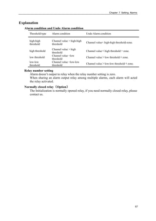
![Chapter 7 Setting Alarms
66
Chapter 7 Setting Alarms
7.1 Alarm Setting
Each channel can set four alarm values, high high alarm, high alarm, low alarm and low
low alarm.
CAUTION
Set the measurement range before setting the alarm.
All of the alarm settings of a channel are canceled in the following cases:
When the signal type is changed(Volt, Resistance)
When the input range is changed
When the setting compensation or square root operation
Procedure
Press [Page] and [En] at the same time, enter the configuration menu.
Use arrow keys and [En] to input the password, enter the [Input] screen.
1. Select the alarm channel
The setting method is the same as the signal type and signal range
2. Set the alarm threshold value
The threshold value must in the channel range.
3. Set the alarm threshold value zone
Prevent the relay frequently action when the signal surged by the alarm threshold
value.
4. Set relay number
Output the relay with setting serial number when an alarm occurs.
Confirming operation
After the parameter setting, select [Exit] there is a Frame.
Select [Yes] to save setting content, and exit [Input] screen.
Select [No] to cancel setting content, and exit [Input] screen.
Select [Cancel] to continue setting parameters in [Input] screen.](https://image.slidesharecdn.com/paperlessrecorderusermanual-180305083513/85/Paperless-recorder-user-manual-76-320.jpg)
![Chapter 7 Setting Alarms
68
7.2 Setting the Relay Delay Period
Procedure
Press [Page] and [En] at the same time, enter the configuration menu.
Use arrow keys and [En] to input the password, enter the [System] screen.
About the input method of editing parameter, see section『Common key operations』
The Relay Delay Period
For preventing the relay mistake action, in appearance system group state, relay time
lapse can set 0-10 seconds to delay trigger under the system configuration.
Think that the queen who gives an alarm coming into being continues setting up
second of inner signal being in the state giving an alarm without exception or
continues setting up second of inner signal without exception in eliminating
newspaper state, relay only meeting action.
The relay will action when the continue setting second signal under alarm state or
undo alarm state.
Confirming operation
After the parameter setting, select [Exit] there is a Frame.
Select [Yes] to save setting content, and exit [System] screen.
Select [No] to cancel setting content, and exit [System] screen.
Select [Cancel] to continue setting parameters in [System] screen.](https://image.slidesharecdn.com/paperlessrecorderusermanual-180305083513/85/Paperless-recorder-user-manual-78-320.jpg)
![Chapter 8 Setting Analog Outputs
69
Chapter 8 Setting Analog Outputs
8.1 Analog Outputs Setting
The instrument provides 4-20mA analog output.
Procedure
Press [Page] and [En] at the same time, enter the configuration menu.
Use arrow keys and [En] to input the password, enter the [Output] screen.
1. Set the output source channel
Set the source of this channel output value.
2. Output the adjust value
Output value = Current value ×K + B。
Confirming operation
After the parameter setting, select [Exit] there is a Frame.
Select [Yes] to save setting content, and exit [Output] screen.
Select [No] to cancel setting content, and exit [Output] screen.
Select [Cancel] to continue setting parameters in [Output] screen.
Explanation
The analog output only supports 4-20mA
According to the channel measurement range, converts the source channel value to
percentage, then transforms to 4-20mA analog output.
When there is no output source channel , the analog output will fix to4mA。](https://image.slidesharecdn.com/paperlessrecorderusermanual-180305083513/85/Paperless-recorder-user-manual-79-320.jpg)
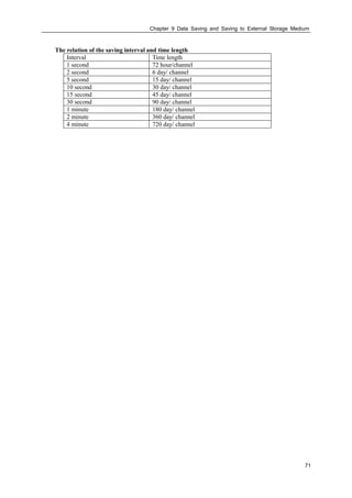
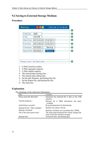
![Chapter 9 Data Saving and Saving to External Storage Medium
70
Chapter 9 Data Saving and Saving to External Storage
Medium
9.1 Setting the Saving Interval of Internal Memory
Procedure
Press [Page] and [En] at the same time, enter the configuration menu.
Use arrow keys and [En] to input the password, enter the [System] screen.
Set the saving interval
User can choose 1s/2s/5s/10s/15s/30s/1min/2min/4min.
Confirming operation
After the parameter setting, select [Exit] there is a Frame.
Select [Yes] to save setting content, and exit [System] screen.
Select [No] to cancel setting content, and exit [System] screen.
Select [Cancel] to continue setting parameters in [System] screen.
Explanation
The sample period is 1 second, so the smallest records interval is 1 second.
Increasing the interval can prolong the time length of storage data.
Note
The interior saving historical data will be invalidation if you modify the saving
interval, therefore, please backup the historical data before you modify it, prevents
the loss.](https://image.slidesharecdn.com/paperlessrecorderusermanual-180305083513/85/Paperless-recorder-user-manual-80-320.jpg)
![Chapter 10 Setting Temperature pressure Parameters
73
Chapter 10 Setting Temperature pressure Parameters
10.1 Set Temperature And Pressure Compensation Model And
The Flow Channel Parameters
This section describes how to set the parameters of temperature and
pressurecompensation model, flow channel, measuring devices and measuring dielectric,
etc.
Operation
Press the [page] and [En], enter the configuration menu.
Use the [arrow keys] and [En] button, enter the password, and then select to enter the
[compensation].
Compensation 2013-04-13 12:58:28
Compensation:
Flow Channel:
Measure Device:
Measure Media:
Accumulate Rate:
Little Flow Fill:
Over Scale Set:
Power-off Fill:
Local Atm Pressure:
Compensation1
Chnl01
Orifice
Steam
1
100%
0%
0.1013MPa
0%
Configure Exit
0%
1. Compensation
Select the compensation channel, a total number of four channels. Select with [Up
and Down] key.
2. Flow channel
set the compensation flow channel. Select with [Up and Down] key.
3. Measuring device
set the compensation medium measurement device, which has a plate, vortex
(frequency), vortex (mA). Select with [Up and Down] key .
4. Measuring medium
set the measurement medium, which has steam, water and general gases. Select with
[Up and Down] key.
5. Cumulative rate
set accumulation rate values, according to [the instantaneous value ×magnification].
Press [En] key to modify the settings, [up and down] key to adjust.
6. Small flow fill
the first setting value is the percentage of small flow limit; the second setting value](https://image.slidesharecdn.com/paperlessrecorderusermanual-180305083513/85/Paperless-recorder-user-manual-83-320.jpg)
![Chapter 10 Setting Temperature pressure Parameters
74
is the percentage of compensation. The Percentage is all flow range percentage. To
adjust settings with [Up and Down] keys.
When the instantaneous flow rate is less than the first set value, the flow
accumulation value according to make up the second set.
7. Over-range setting
when instantaneous flow exceeds maximum range, and then it will lead to top
destruction, according to [flow range ×set value] accumulation. To adjust settings
with [Up and Down] keys
8. Power-down fill
Cumulative value and the statements during a power outage is according to [flow
range ×set value] calculated compensation. To adjust settings with [Up and Down]
keys.
9. Parameter setting
Press [En] key to enter the temperature and pressure compensation parameter setting
screen.
Confirming operation
After the parameter setting, select [Exit] there is a Frame.
Select [Yes] to save setting content, and exit [compensation] screen.
Select [No] to cancel setting content, and exit [compensation] screen.
Select [Cancel] to continue setting parameters in [compensation] screen.
Explain
During flow accumulation, it should the first cut the small signal, and then calculated the
flow after compensation according to temperature and pressure compensation formula.
Then have calculation on small flow compensation, over range compensation,
accumulation, and finally get the last flow to accumulate.](https://image.slidesharecdn.com/paperlessrecorderusermanual-180305083513/85/Paperless-recorder-user-manual-84-320.jpg)
![Chapter 10 Setting Temperature pressure Parameters
75
10.2 Orifice + Steam Parameter Setting
This section describes measuring device (orifice) and measuring medium (steam)
parameters setting.
Operation
Press the [page] + [En], enter the configuration menu.
Use the [arrow keys] and [En] button, enter the password, and then select to enter the
[flow compensation].
Move the cursor to the [Parameter setting] button, press the [En] key to enter the
parameter setting screen.
Configure 2013-04-13 12:58:28
Removal:
Square:
Pressure-Diff Scale:
Pressure-Diff Unit:
Flow unit:
Actual Temperature:
Actual Pressure:
Designed Temperature:
0.0%
No
4.00
KPa
t/h
Input
0 ℃
Chnl03
Finish
20.00
Mpa
Input Chnl02 ℃
Designed Pressure: 0 MPa
1. Resection of the small signal
The setting range is 0.0-9.9%, expressed by a percentage. If Input differential signal
is less than set value range, it will be the limit input. To adjust settings with [Up and
Down] keys
2. Square root
To have square root calculation on the percentage of the differential pressure signal.
To adjust settings with [Up and Down] keys
3. Differential pressure range
To acquire differential signal to display range. Press [En] key to modify the settings.
To adjust settings with [Up and Down] keys
4. Differential pressure units
Differential pressure signal units is involved in operations. It is fixed at KPa.
5. Flow units
Flow units is involved in operations, the default is t / h (or t / h, kg / h). Press [up and
down] key to select.
6. Temperature conditions
Input type: [enter], [set] (two options).
[Input]: Select the signal channel input for the temperature value, press [up and](https://image.slidesharecdn.com/paperlessrecorderusermanual-180305083513/85/Paperless-recorder-user-manual-85-320.jpg)
![Chapter 10 Setting Temperature pressure Parameters
76
down] key to select.
[Set]: Set the constant value for temperature. Press [En] button to change settings,
press [up and down] key to adjust.
7. Pressure condition
Input type: [enter], [set] (two options).
[Input]: Select the signal channel input for the pressure value, press [up and down]
key to select.
[Set]: Set the constant value for pressure. Press [En] button to change settings, press
[up and down] key to adjust.
8. Set temperature
Set temperature value. Press [En] button to change settings, press [up and down] key
to adjust.
9. Design pressure
Set pressure value. Press [En] button to change settings, press [up and down] key to
adjust.
10. Cursor to the [Finish] button, press the [En] button to return.](https://image.slidesharecdn.com/paperlessrecorderusermanual-180305083513/85/Paperless-recorder-user-manual-86-320.jpg)
![Chapter 10 Setting Temperature pressure Parameters
77
10.3 Orifice + Water Parameter Setting
This section describes measuring device (orifice) and measuring medium (water)
parameters setting.
Operating
Press the [page] + [En], enter the configuration menu.
Use the [arrow keys] and [En] button, enter the password, and then select to enter the
[flow compensation].
Move the cursor to the [Parameter setting] button, press the [En] key to enter the
parameter setting screen.
Configure 2013-04-13 12:58:28
Removal:
Square:
Pressure-Diff Scale:
Pressure-Diff Unit:
Flow unit:
Actual Temperature:
Actual Pressure:
Designed Temperature:
0.0%
No
4.00
KPa
t/h
Input
0 C
Chnl02
Finish
20.00
℃
0.6MPa
1. Resection of the small signal
The setting range is 0.0-9.9%, expressed by a percentage. If Input differential signal
is less than set value range, it will be the limit input. To adjust settings with [Up
and Down] keys
2. Square root
To have square root calculation on the percentage of the differential pressure signal.
To adjust settings with [Up and Down] keys
3. Differential pressure range
To acquire differential signal to display range. Press [En] key to modify the settings.
To adjust settings with [Up and Down] keys
4. Differential pressure units
Differential pressure signal units is involved in operations. It is fixed at KPa.
5. Flow units
Flow units is involved in operations, the default is t / h (or t / h, kg / h). Press [up and
down] key to select.
6. Temperature conditions
Input type: [enter], [set] (two options).
[Input]: Select the signal channel input for the temperature value, press [up and](https://image.slidesharecdn.com/paperlessrecorderusermanual-180305083513/85/Paperless-recorder-user-manual-87-320.jpg)
![Chapter 10 Setting Temperature pressure Parameters
78
down] key to select.
[Set]: Set the constant value for temperature. Press [En] button to change settings,
press [up and down] key to adjust.
7. Pressure condition
Input type: [enter], [set] (two options).
[Input]: Select the signal channel input for the pressure value, press [up and down]
key to select.
[Set]: Set the constant value for pressure. Press [En] button to change settings, press
[up and down] key to adjust.
8. Set temperature
Set temperature value. Press [En] button to change settings, press [up and down] key
to adjust.
9. Cursor to the [Finish] button, press the [En] button to return.](https://image.slidesharecdn.com/paperlessrecorderusermanual-180305083513/85/Paperless-recorder-user-manual-88-320.jpg)
![Chapter 10 Setting Temperature pressure Parameters
79
10.4 Orifice + General Gas Parameter Setting
This section describes measuring device (orifice) and measuring medium (general gas)
parameters setting.
Operating
Press the [page] + [En], enter the configuration menu.
Use the [arrow keys] and [En] button, enter the password, and then select to enter
the [flow compensation].
Move the cursor to the [Parameter setting] button, press the [En] key to enter the
parameter setting screen.
Configure 2013-04-13 12:58:28
Removal:
Pressure-Diff Scale:
Pressure-Diff Unit:
Flow unit:
Actual Temperature:
Actual Pressure:
Designed Temperature:
Designed Pressure:
0.0%
4.00
KPa
t/h
Input
0 C
0 MPa
Chnl02
Finish
20.00
℃
Input Chnl03 MPa
Square: No
Compress Rate: Table Air
Local atm: 0.1013Mpa
1. Resection of the small signal
The setting range is 0.0-9.9%, expressed by a percentage. If Input differential signal
is less than set value range, it will be the limit input. To adjust settings with [Up
and Down] keys
2. Square root
To have square root calculation on the percentage of the differential pressure signal.
To adjust settings with [Up and Down] keys
3. Differential pressure range
To acquire differential signal to display range. Press [En] key to modify the settings.
To adjust settings with [Up and Down] keys
4. Differential pressure units
Differential pressure signal units is involved in operations. It is fixed at KPa.
5. Flow units
Flow units is involved in operations. It is fixed at m3/h.
6. Temperature conditions
Input type: [enter], [set] (two options).
[Input]: Select the signal channel input for the temperature value, press [up and
down] key to select.
[Set]: Set the constant value for temperature. Press [En] button to change settings,](https://image.slidesharecdn.com/paperlessrecorderusermanual-180305083513/85/Paperless-recorder-user-manual-89-320.jpg)
![Chapter 10 Setting Temperature pressure Parameters
80
press [up and down] key to adjust.
7. Pressure condition
Input type: [enter], [set] (two options).
[Input]: Select the signal channel input for the pressure value, press [up and down]
key to select.
[Set]: Set the constant value for pressure. Press [En] button to change settings, press
[up and down] key to adjust.
8. Set temperature
Set temperature value. Press [En] button to change settings, press [up and down] key
to adjust.
9. Designed pressure
Set design pressure value. Press [En] button to change settings, press [up and down]
key to adjust.
10. Compressibility coefficient
General gas‘s compressibility coefficient. There are [set], [check] two options.
[Settings]: free to set the compression factor. Press [En] button to change settings,
press [up and down] key to adjust.
[Check]: There are three kinds of gas models: air, nitrogen, oxygen, press [up and
down] key to select.
11. The local atmospheric pressure
Atmospheric pressure where the user locates. Press [En] button to change settings,
press [up and down] key to adjust.
12. Cursor to the [Finish] button, press the [En] button to return.](https://image.slidesharecdn.com/paperlessrecorderusermanual-180305083513/85/Paperless-recorder-user-manual-90-320.jpg)
![Chapter 10 Setting Temperature pressure Parameters
81
10.5 Vortex (Frequency) + Steam Parameter Setting
This section describes measuring device (vortex) and measuring medium (steam)
parameters setting.
Operating
Press the [page] + [En], enter the configuration menu.
Use the [arrow keys] and [En] button, enter the password, and then select to enter the
[flow compensation].
Move the cursor to the [Parameter setting] button, press the [En] key to enter the
parameter setting screen.
Configure 2013-04-13 12:58:28
Removal:
K:
Unit of K:
Flow Unit:
Actual temperature:
0%
Times/m3
t/h
Input
Finish
℃Chnl02
Actual pressure: Input MPaChnl03
1
1. Resection of the small signal
the setting range is 0.0-9.9%, expressed by a percentage. If Input differential signal
is less than set value range, it will be the limit input. To adjust settings with [Up and
Down] keys
2. K Vortex average K factor setting.
Press [En] key to modify the settings. . To adjust settings with [Up and Down] keys.
3. K factor unit
K factor unit is involved in operation.
The default is time / m3 (optional times / m3, plays / L). To adjust settings with [Up
and Down] keys
4. Flow units
Traffic units involved in operations, the default is t / h (optional t / h, kg / h), press
[up and down] key to select.
5. Temperature conditions
Input type: [enter], [set] (two options).
[Input]: Select the signal channel input for the temperature value, press [up and
down] key to select.](https://image.slidesharecdn.com/paperlessrecorderusermanual-180305083513/85/Paperless-recorder-user-manual-91-320.jpg)
![Chapter 10 Setting Temperature pressure Parameters
82
[Set]: Set the constant value for temperature. Press [En] button to change settings,
press [up and down] key to adjust.
6. Pressure condition
Choose [0.6MPa] or [1.6Mpa.Press [up and down] key to select.
7. Cursor to the [Finish] button, press the [En] button to return.](https://image.slidesharecdn.com/paperlessrecorderusermanual-180305083513/85/Paperless-recorder-user-manual-92-320.jpg)
![Chapter 10 Setting Temperature pressure Parameters
83
10.6 Vortex (Frequency) + Water Parameter Setting
This section describes the measuring device (vortex (frequency) and measured medium
(water) parameter settings.
Operation
Press the [page] + [En], enter the configuration menu.
Use the [arrow keys] and [En] button, enter the password, and then select to enter
the [flow compensation].
Move the cursor to the [Parameter setting] button, press the [En] key to enter the
parameter setting screen.
Configure 2013-04-13 12:58:28
Removal:
K:
Unit of K:
Flow Unit:
Actual temperature:
0%
Times/m3
t/h
Input
Finish
℃Chnl02
Actual pressure: 0.6MPa
1
1. Resection of the small signal
The setting range is 0.0-9.9%, expressed by a percentage. If Input differential signal
is less than set value range, it will be the limit input. To adjust settings with [Up
and Down] keys
2. K Vortex average K factor setting.
Press [En] key to modify the settings. . To adjust settings with [Up and Down] keys
3. K factor unit
K factor unit is involved in operation.
The default is time / m3 (optional times / m3, plays / L). To adjust settings with
[Up and Down] keys
4. Flow units
Traffic units involved in operations, the default is t / h (optional t / h, kg / h), press
[up and down] key to select.
5. Temperature conditions
Input type: [enter], [set] (two options).
[Input]: Select the signal channel input for the temperature value, press [up and
down] key to select.](https://image.slidesharecdn.com/paperlessrecorderusermanual-180305083513/85/Paperless-recorder-user-manual-93-320.jpg)
![Chapter 10 Setting Temperature pressure Parameters
84
10.7 Vortex (Frequency) + General Gas Parameter Setting
This section describes the measuring device (vortex (frequency) and measured medium
(general gas) parameter settings.
Operation
Press the [page] + [En], enter the configuration menu.
Use the [arrow keys] and [En] button, enter the password, and then select to enter
the [flow compensation].
Move the cursor to the [Parameter setting] button, press the [En] key to enter the
parameter setting screen.
Configure 2013-04-13 12:58:28
Removal:
K:
Unit of K:
Flow Unit:
Actual temperature:
0%
Times/m3
t/h
Input
Finish
℃Chnl02
Actual pressure: Input MPaChnl03
Compress Rate: Table Air
Local atm pressure: 0.1013MPa
1
1. Resection of the small signal
The setting range is 0.0-9.9%, expressed by a percentage. If Input differential signal
is less than set value range, it will be 0. To adjust settings with [Up and Down] keys.
2. K Vortex average K factor setting.
Press [En] key to modify the settings. . To adjust settings with [Up and Down] keys.
3. K factor unit
K factor unit is involved in operation.
The default is time / m3 (optional times / m3, plays / L). To adjust settings with [Up
and Down] keys.
4. Flow units
Flow units is involved in operations. It is fixed at m3/h.
5. Temperature conditions
Input type: [enter], [set] (two options).
[Input]: Select the signal channel input for the temperature value, press [up and
down] key to select.
[Set]: Set the constant value for temperature. Press [En] button to change settings,
press [up and down] key to adjust.](https://image.slidesharecdn.com/paperlessrecorderusermanual-180305083513/85/Paperless-recorder-user-manual-94-320.jpg)
![Chapter 10 Setting Temperature pressure Parameters
85
6. Pressure condition
Input type: [enter], [set] (two options).
[Input]: Select the signal channel input for the pressure value, press [up and down]
key to select.
[Set]: Set the constant value for pressure. Press [En] button to change settings, press
[up and down] key to adjust.
7. Compressibility coefficient
General gas‘s compressibility coefficient. There are [set], [check] two options.
[Settings]: free to set the compression factor. Press [En] button to change settings,
press [up and down] key to adjust.
[Check]: There are three kinds of gas models: air, nitrogen, oxygen, and press [up
and down] key to select.
8. The local atmospheric pressure
Atmospheric pressure where the user locates. Press [En] button to change settings,
press [up and down] key to adjust.
9. Cursor to the [Finish] button, press the [En] button to return.](https://image.slidesharecdn.com/paperlessrecorderusermanual-180305083513/85/Paperless-recorder-user-manual-95-320.jpg)
![Chapter 10 Setting Temperature pressure Parameters
86
10.8 Vortex (mA) + Steam Parameter Setting
This section describes the measuring device (vortex (ma) and measured medium (steam)
parameter settings.
Operation
Press the [page] + [En], enter the configuration menu.
Use the [arrow keys] and [En] button, enter the password, and then select to enter
the [flow compensation].
Move the cursor to the [Parameter setting] button, press the [En] key to enter the
parameter setting screen.
Configure 2013-04-13 12:58:28
Removal:
Volume Scale:
Volume Unit:
Flow Unit:
Actual temperature:
0%
4.00
m3
/h
t/h
Input
20.00
Finish
℃Chnl02
Actual pressure: Input MPaChnl03
1. Resection of the small signal
The setting range is 0.0-9.9%, expressed by a percentage. If Input differential signal
is less than set value range, it will be input limit. To adjust settings with [Up and
Down] keys
2. Volume Range
Collect display range of volume signal, and press [En key to modify the settings, and
press [up and down] key to adjust.
3. Volume unit
Volume unit is involved in operations, fixed at m3 / h.
4. Flow units
Flow units is involved in operations, the default is t / h (optional t / h, kg / h), press
[up and down] key to select.
5. Temperature conditions
Input type: [enter], [set] (two options).
[Input]: Select the signal channel input for the temperature value, press [up and
down] key to select.
[Set]: Set the constant value for temperature. Press [En] button to change settings,](https://image.slidesharecdn.com/paperlessrecorderusermanual-180305083513/85/Paperless-recorder-user-manual-96-320.jpg)
![Chapter 10 Setting Temperature pressure Parameters
87
press [up and down] key to adjust.
6. Pressure condition
Input type: [enter], [set] (two options).
[Input]: Select the signal channel input for the pressure value, press [up and down]
key to select.
[Set]: Set the constant value for pressure. Press [En] button to change settings, press
[up and down] key to adjust.
7. Cursor to the [Finish] button, press the [En] button to return.](https://image.slidesharecdn.com/paperlessrecorderusermanual-180305083513/85/Paperless-recorder-user-manual-97-320.jpg)
![Chapter 10 Setting Temperature pressure Parameters
88
10.9 Vortex (mA) + Water Parameter Setting
This section describes the measuring device (vortex (ma) and measured medium (water)
parameter settings.
Operation
Press the [page] + [En], enter the configuration menu.
Use the [arrow keys] and [En] button, enter the password, and then select to enter
the [flow compensation].
Move the cursor to the [Parameter setting] button, press the [En] key to enter the
parameter setting screen.
Configure 2013-04-13 12:58:28
Removal:
Volume Scale:
Volume Unit:
Flow Unit:
Actual temperature:
0%
4.00
m3
/h
t/h
Input
20.00
Finish
℃Chnl02
Actual pressure: 0.6MPa
1. Resection of the small signal
The setting range is 0.0-9.9%, expressed by a percentage. If Input differential signal
is less than set value range, it will be input limit. To adjust settings with [Up and
Down] keys.
2. Volume Range
Collect display range of volume signal, and press [En key to modify the settings, and
press [up and down] key to adjust.
3. Volume unit
Volume unit is involved in operations, fixed at m3 / h.
4. Flow units
Flow units is involved in operations, the default is t / h (optional t / h, kg / h), press
[up and down] key to select.
5. Temperature conditions
Input type: [enter], [set] (two options).
[Input]: Select the signal channel input for the temperature value, press [up and
down] key to select.
[Set]: Set the constant value for temperature. Press [En] button to change settings,](https://image.slidesharecdn.com/paperlessrecorderusermanual-180305083513/85/Paperless-recorder-user-manual-98-320.jpg)
![Chapter 10 Setting Temperature pressure Parameters
89
press [up and down] key to adjust.
6. Pressure condition
Input type: [enter], [set] (two options).
Choose [0.6MPa] or [1.6Mpa], and press [up and down] key to adjust.
7. Cursor to the [Finish] button, press the [En] button to return.](https://image.slidesharecdn.com/paperlessrecorderusermanual-180305083513/85/Paperless-recorder-user-manual-99-320.jpg)
![Chapter 10 Setting Temperature pressure Parameters
90
10.10 Vortex (mA) + General Gas Parameter Setting
This section describes the measuring device (vortex (ma) and measured medium (general
gas) parameter settings.
Operation
Press the [page] + [En], enter the configuration menu.
Use the [arrow keys] and [En] button, enter the password, and then select to enter
the [flow compensation].
Move the cursor to the [Parameter setting] button, press the [En] key to enter the
parameter setting screen.
Configure 2013-04-13 12:58:28
Removal:
Volume Scale:
Volume Unit:
Flow Unit:
Actual temperature:
0%
4.00
m3
/h
t/h
Input
20.00
Finish
℃Chnl02
Actual pressure: Input MPaChnl03
Compress Rate: Table Air
Local atm pressure: 0.1013MPa
1. Resection of the small signal
The setting range is 0.0-9.9%, expressed by a percentage. If Input differential signal
is less than set value range, it will be 0. To adjust settings with [Up and Down] keys.
2. Volume Range
Collect display range of volume signal, and press [En key to modify the settings, and
press [up and down] key to adjust.
3. Volume unit
Volume unit is involved in operations, fixed at m3 / h.
4. Flow units
Flow units are involved in operations. It is fixed at m3/h.
5. Temperature conditions
Input type: [enter], [set] (two options).
[Input]: Select the signal channel input for the temperature value, press [up and
down] key to select.
[Set]: Set the constant value for temperature. Press [En] button to change settings,
press [up and down] key to adjust.
6. Pressure condition](https://image.slidesharecdn.com/paperlessrecorderusermanual-180305083513/85/Paperless-recorder-user-manual-100-320.jpg)
![Chapter 10 Setting Temperature pressure Parameters
91
Input type: [enter], [set] (two options).
[Input]: Select the signal channel input for the pressure value, press [up and down]
key to select.
[Set]: Set the constant value for pressure. Press [En] button to change settings, press
[up and down] key to adjust.
7. Compressibility coefficient
General gas‘s compressibility coefficient. There are [set], [check] two options.
[Settings]: free to set the compression factor. Press [En] button to change settings,
press [up and down] key to adjust.
[Check]: There are three kinds of gas models: air, nitrogen, oxygen, and press [up
and down] key to select.
8. The local atmospheric pressure
Atmospheric pressure where the user locates. Press [En] button to change settings,
press [up and down] key to adjust.
9. Cursor to the [Finish] button, press the [En] button to return.](https://image.slidesharecdn.com/paperlessrecorderusermanual-180305083513/85/Paperless-recorder-user-manual-101-320.jpg)
![Chapter 11 Setting Report
92
Chapter 11 Setting Report
11.1 Setting specifications of report
Procedure
Press [Page] and [En] at the same time, enter the configuration menu.
Use arrow keys and [En] to input the password, enter the [Report] screen.
Report 2013-04-13 13:21:32
Report type: Daily
Exit
Report time: 00 o’clock
1. Report type
Select report type for display and saving, there are four options: Hourly, 8Hourly,
12Hourly and Daily (you can get into the Report-Monthly screen while at the screen
of Report-Daily)
2. Report time
Setting report time. Using [Up] or [Down] key to Configure the report time from 00
o’clock to 07 o’clock.
Confirming operation
After the parameter setting, select [Exit] there is a Frame.
Select [Yes] to save setting content, and exit [Report] screen.
Select [No] to cancel setting content, and exit [Report] screen.
Select [Cancel] to continue setting parameters in [Report] screen.
Warning
Do not change the report type at will; the change will cause the internal data to be
chaotic.](https://image.slidesharecdn.com/paperlessrecorderusermanual-180305083513/85/Paperless-recorder-user-manual-102-320.jpg)
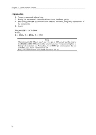
![Chapter 12 Communication Function
93
Chapter 12 Communication Function
12.1 Communication Using RS232C (Option)
Procedure
Press [Page] and [En] at the same time, enter the configuration menu.
Use arrow keys and [En] to input the password, enter the [system] screen.
Item Content
Communication address 0 – 255
Communication baud rate 1200/2400/4800/9600/19200/38400/57600
Communication parity mode None/Odd/Even
Confirming operation
After the parameter setting, select [Exit] there is a Frame.
Select [Yes] to save setting content, and exit [System] screen.
Select [No] to cancel setting content, and exit [System] screen.
Select [Cancel] to continue setting parameters in [System] screen.](https://image.slidesharecdn.com/paperlessrecorderusermanual-180305083513/85/Paperless-recorder-user-manual-103-320.jpg)
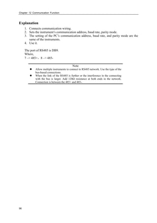
![Chapter 12 Communication Function
95
12.2 Communication Using RS485(Option)
Procedure
Press [Page] and [En] at the same time, enter the configuration menu.
Use arrow keys and [En] to input the password, enter the [system] screen.
Item Content
Communication address 0 – 255
Communication baud rate 1200/2400/4800/9600/19200/38400/57600
Communication parity mode None/Odd/Even
Confirming operation
After the parameter setting, select [Exit] there is a Frame.
Select [Yes] to save setting content, and exit [System] screen.
Select [No] to cancel setting content, and exit [System] screen.
Select [Cancel] to continue setting parameters in [System] screen.](https://image.slidesharecdn.com/paperlessrecorderusermanual-180305083513/85/Paperless-recorder-user-manual-105-320.jpg)
![Chapter 12 Communication Function
98
12.4 Auto Print Function Setting
Procedure
Press [Page] and [En] at the same time, enter the configuration menu.
Use arrow keys and [En] to input the password, enter the [Timer] screen.
1. Set the timer print function
Move the cursor to [Timer Prt], choose it with [Up] and [Down]
[Yes]: The timer print function is opened.
[No]: The timer print function is closed.
2. The starting time
3. Interval: Between two printing time intervals.
Confirming operation
After the parameter setting, select [Exit] there is a Frame.
Select [Yes] to save setting content, and exit [Timer] screen.
Select [No] to cancel setting content, and exit [Timer] screen.
Select [Cancel] to continue setting parameters in [Timer] screen.
Note
When use the timer print function, the printer must connect with the
instrumental the time.
About the printer setting, see section 10.3.](https://image.slidesharecdn.com/paperlessrecorderusermanual-180305083513/85/Paperless-recorder-user-manual-108-320.jpg)
![Chapter 13 Initializing Data
99
Chapter 13 Initializing Data
13.1 Restore Factory Setting
Procedure
Press [Page] and [En] at the same time, enter the configuration menu.
Use arrow keys and [En] to input the password, enter the [system] screen.
Restore factory setting
Move the cursor to [Factory Setting], press [En].
Confirming operation
Select [Yes] and press [En] to restore factory setting.
Select [No] and press [En] to cancel factory setting.
After Restore Factory setting, select [Exit] there is a Frame.
Select [Yes] to save setting content, and exit [System] screen.
Select [No] to cancel setting content, and exit [System] screen.
Select [Cancel] to continue setting parameters in [System] screen.
Note
After factory setting, the historical data stored in instrument will be cleared.
Before the factory setting, please backup the historical data.](https://image.slidesharecdn.com/paperlessrecorderusermanual-180305083513/85/Paperless-recorder-user-manual-109-320.jpg)
![Chapter 13 Initializing Data
100
Explanation
The influencing parameter tabulation
Type Name Value
System parameter Alias Overview
Password 000000
Display parameter Direction Horizontal
Group1 Enable
Group1 – Chnl1 –purple
Group2 –Chnl2 – green
Group3 –Chnl3 – blue
Group4 –Chnl4 – yellow
Group2 – 4 Prohibited
Data save
parameter
Interval 02 S
Communication
parameter
Address 8
Baud rate 9600
Parity None
Timing printer Prohibited
Analog input
parameter
(all channels)
Tag Channel[No.]
Type 4-20mA
Unit %
lower limit 4.00
Upper limit 20.00
Accumulation No
Accumulation rate 1
Vacuum No
Filter 0.0 sec.
Burnout Minimum
Cold junction adjustment 0.0
Square No
Cut 0.0%
Adjust value K 1.00
Adjust value B 0.00
Alarm parameter
(all channels)
Alarm low low threshold 4.00
Alarm low threshold 4.00
Alarm high threshold 20.00
Alarm high high threshold 20.00
Alarm contact(all alarm)) 0
Zone 0.00
Analog output
parameter
(all loops)
Analog output No
Adjust value K 1.00
Adjust value B 0.00](https://image.slidesharecdn.com/paperlessrecorderusermanual-180305083513/85/Paperless-recorder-user-manual-110-320.jpg)
![Chapter 13 Initializing Data
101
13.2 Purge Alarm Summary
Procedure
Press [Page] and [En] at the same time, enter the configuration menu.
Use arrow keys and [En] to input the password, enter the [system] screen.
Purge Alarm Summary
Move the cursor to [Purge Alarm], press [En].
Confirming operation
Select [Yes] and press [En] to purge alarm summary.
Select [NO] and press [En] to cancel purge alarm summary.
After Purge Alarm Summary, select [Exit] there is a Frame.
Select [Yes] to save setting content, and exits [System] screen.
Select [No] to cancel setting content, and exits [System] screen.
Select [Cancel] to continue setting parameters in [System] screen.
Explanation
Clearing alarm list will eliminate alarm records in memory, and can not be recovered.
Clearing alarm list will not affect other parameters and functions of this instrument.](https://image.slidesharecdn.com/paperlessrecorderusermanual-180305083513/85/Paperless-recorder-user-manual-111-320.jpg)
![Chapter 13 Initializing Data
102
13.3 Purge Accumulation Data
Procedure
Press [Page] and [En] at the same time, enter the configuration menu.
Use arrow keys and [En] to input the password, enter the [Input] screen.
Clear Accumulate
Move the cursor to [Clear Acc], press [En] key.
Confirming operation
Select [Yes] and press [En] to purge accumulation data.
Select [NO] and press [En] to cancel purge accumulation data.
After Purge Alarm Summary, select [Exit] there is a Frame.
Select [Yes] to save setting content, and exits [Input] screen.
Select [No] to cancel setting content, and exits [Input] screen.
Select [Cancel] to continue setting parameters in [Input] screen.
Explanation
Clearing accumulation will eliminate accumulation records in memory, and can not be
recovered.
Clearing accumulation will not affect other parameters and functions of this instrument.](https://image.slidesharecdn.com/paperlessrecorderusermanual-180305083513/85/Paperless-recorder-user-manual-112-320.jpg)
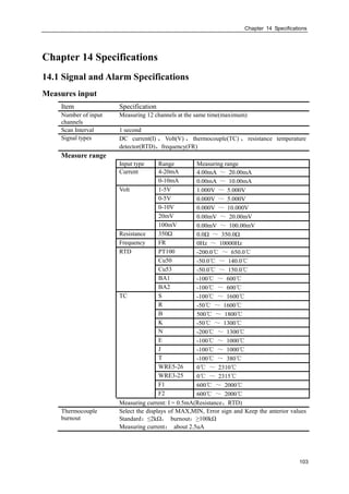
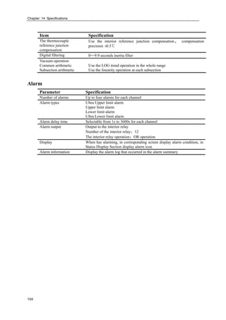
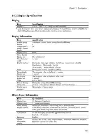
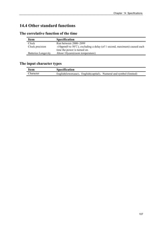
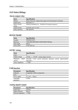
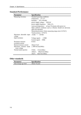
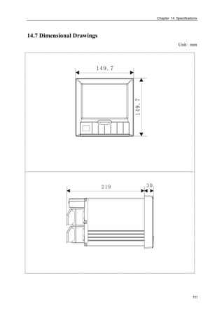
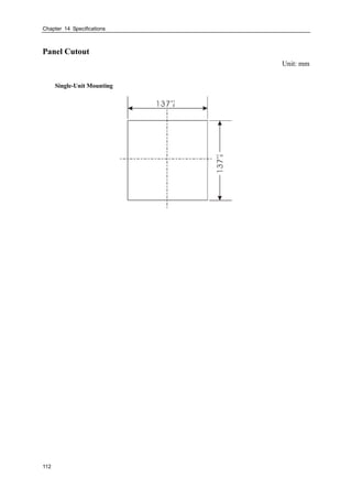

This document is a user manual for a paperless recorder. It provides instructions on installing and setting up the recorder, describes its key functions and parts, and explains how to operate the recorder. The manual is divided into chapters that cover an overview of functions, installation, names of parts, operation screens, system configurations, input/output settings, data storage, alarms, reports, communication functions, and specifications. It aims to ensure the recorder is used correctly by providing detailed information on its functions, settings, wiring methods, operation methods, and troubleshooting.


