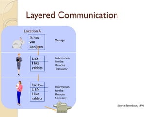
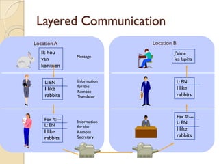
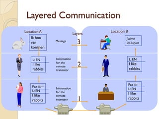
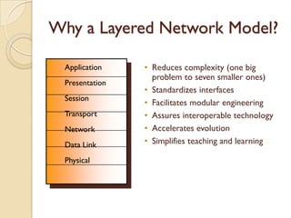
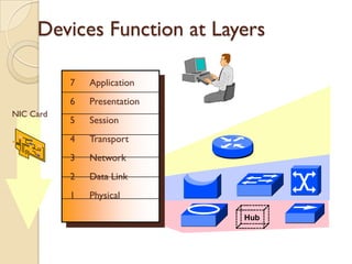
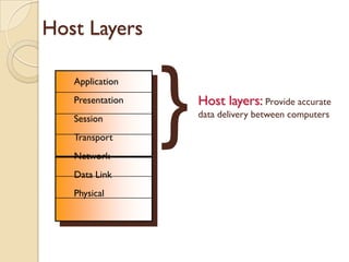
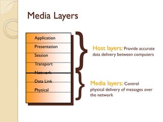
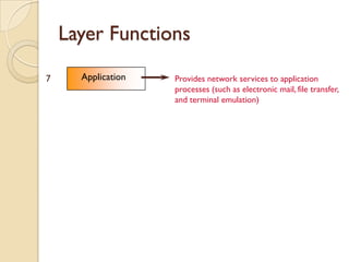
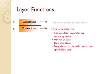
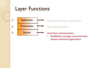
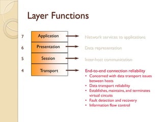
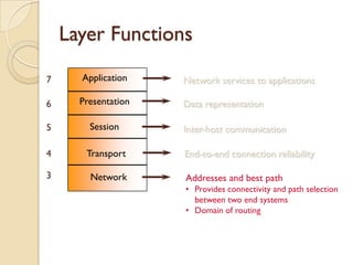
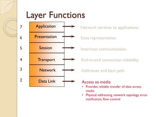
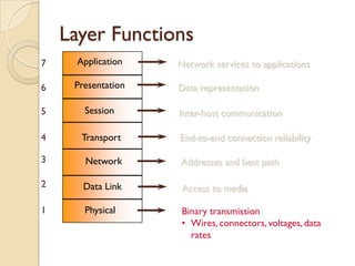
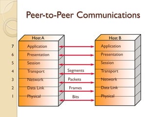
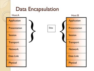
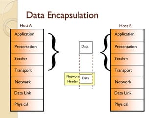
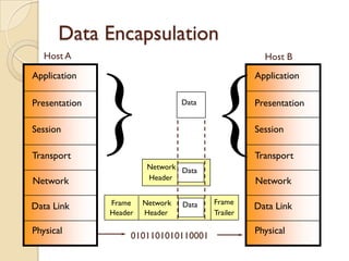
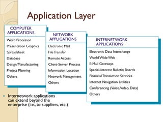
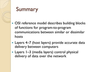
The Layered Model


© 1999, Cisco Systems, Inc.   www.cisco.com
Layered Communication
Location A
   Ik hou
                Message
   van
   konijnen


    L: EN       Information
                for the
    I like      Remote
    rabbits     Translator


    Fax #:---   Information
    L: EN       for the
    I like      Remote
    rabbits     Secretary

                              Source: Tanenbaum, 1996
Layered Communication
Location A                    Location B
   Ik hou                              J’aime
                Message
   van                                 les lapins
   konijnen


    L: EN       Information                L: EN
                for the                    I like
    I like      Remote
    rabbits     Translator                 rabbits


                                           Fax #:---
    Fax #:---   Information                L: EN
    L: EN       for the
    I like                                 I like
                Remote
    rabbits     Secretary                  rabbits
Layered Communication
Location A                             Location B
                              Layers
   Ik hou                                       J’aime
   van          Message
                                3               les lapins
   konijnen


    L: EN       Information                         L: EN
    I like      for the
                remote          2                   I like
                                                    rabbits
    rabbits     translator


                                                    Fax #:---
    Fax #:---   Information                         L: EN
    L: EN       for the
    I like                                          I like
                remote
    rabbits     secretary       1                   rabbits
Why a Layered Network Model?

7    Application    • Reduces complexity (one big
                      problem to seven smaller ones)
6    Presentation
                    • Standardizes interfaces
5    Session
                    • Facilitates modular engineering
4    Transport      • Assures interoperable technology
3    Network        • Accelerates evolution
2    Data Link      • Simplifies teaching and learning

1    Physical
Devices Function at Layers

           7   Application
           6   Presentation
NIC Card
           5   Session
           4   Transport
           3   Network
           2   Data Link
           1   Physical

                              Hub
Host Layers


                   }
7   Application
6   Presentation       Host layers: Provide accurate
5   Session            data delivery between computers

4   Transport
3   Network
2   Data Link
1   Physical
Media Layers


                    }
7    Application
6    Presentation        Host layers: Provide accurate
5    Session             data delivery between computers

4    Transport


                    }
3    Network
2    Data Link
                        Media layers: Control
1    Physical           physical delivery of messages over
                        the network
Layer Functions

7     Application   Provides network services to application
                    processes (such as electronic mail, file transfer,
                    and terminal emulation)
Layer Functions

7     Application    Network services to applications

6     Presentation   Data representation
                     • Ensures data is readable by
                       receiving system
                     • Format of data
                     • Data structures
                     • Negotiates data transfer syntax for
                       application layer
Layer Functions

7     Application    Network services to applications

6     Presentation   Data representation

5       Session      Inter-host communication
                     • Establishes, manages, and terminates
                         sessions between applications
Layer Functions

7     Application    Network services to applications

6     Presentation   Data representation

5       Session      Inter-host communication

4      Transport     End-to-end connection reliability
                     • Concerned with data transport issues
                       between hosts
                     • Data transport reliability
                     • Establishes, maintains, and terminates
                       virtual circuits
                     • Fault detection and recovery
                     • Information flow control
Layer Functions

7     Application    Network services to applications

6     Presentation   Data representation

5       Session      Inter-host communication

4      Transport     End-to-end connection reliability

3       Network      Addresses and best path
                     • Provides connectivity and path selection
                       between two end systems
                     • Domain of routing
Layer Functions
7     Application    Network services to applications

6     Presentation   Data representation

5       Session      Inter-host communication

4      Transport     End-to-end connection reliability

3       Network      Addresses and best path

2       Data Link    Access to media
                     • Provides reliable transfer of data across
                       media
                     • Physical addressing, network topology, error
                       notification, flow control
Layer Functions
7    Application    Network services to applications

6    Presentation   Data representation

5      Session      Inter-host communication

4     Transport     End-to-end connection reliability

3      Network      Addresses and best path

2      Data Link     Access to media

1      Physical      Binary transmission
                     • Wires, connectors, voltages, data
                       rates
Peer-to-Peer Communications

      Host A                      Host B
7   Application               Application
6   Presentation              Presentation
5   Session                   Session
4   Transport      Segments   Transport
3   Network        Packets    Network
2   Data Link      Frames     Data Link
1   Physical         Bits     Physical
Data Encapsulation
   Host A                    Host B
Application                Application

Presentation

Session

Transport
               } { Data    Presentation

                           Session

                           Transport

Network                    Network

Data Link                  Data Link

Physical                   Physical
Data Encapsulation
   Host A                        Host B
Application                    Application

Presentation

Session

Transport
               } {      Data


                Network Data
                Header
                               Presentation

                               Session

                               Transport

Network                        Network

Data Link                      Data Link

Physical                       Physical
Data Encapsulation
   Host A                                            Host B
Application                                        Application

Presentation

Session

Transport
               } {                Data


                         Network Data
                         Header
                                                   Presentation

                                                   Session

                                                   Transport

Network                                            Network

               Frame    Network   Data   Frame
Data Link                                          Data Link
               Header   Header           Trailer

Physical                                           Physical
                    0101101010110001
Layers 1 & 2:
         Physical & Data Link Layers


© 1999, Cisco Systems, Inc.   www.cisco.com
Physical and Logical Addressing


0000.0c12.3456
MAC Address
            24 bits            24 bits


       Vendor Code       Serial Number

           0000.0c12. 3456
                      ROM
                      RAM


• MAC address is burned into ROM on a network
  interface card
Layer 3:
         Network Layer


© 1999, Cisco Systems, Inc.   www.cisco.com
Network Layer: Path Determination


                 Which Path?
                 Which Path?


• Layer 3 functions to find the best
  path through the internetwork
Network Layer: Communicate Path


                            5
                2                       9
                                6   8
                        4
                                            10   11
            1       3
                                    7


   Addresses represent the path of media
    connections
   Routing helps contain broadcasts
Addressing—Network and Node

    Network       Node

       1            1
                                                      2.1
                    2
                    3                1.2

       2            1                 1.3       1.1     3.1

       3            1


• Network address—Path part used by the router
• Node address—Specific port or device on the network
Protocol Addressing Variations

General      Network      Node
Example                    1
                 1


             Network      Host
 TCP/IP
Example         10.      8.2.48      (Mask 255.0.0.0)


             Network        Node
Novell IPX
 Example     1aceb0b.   0000.0c00.6e25
Network Layer
       Protocol Operations
X                                                  Y
                                      C
                                      C

          A
          A


   Each router provides its services to support
    upper layer functions
Network Layer
                   Protocol Operations
      X                                                              Y
                                                       C
                                                       C

                     A
                     A

                                     B
                                     B
     Host X                                                   Host Y
    Application                                              Application
    Presentation                                             Presentation
    Session          Router A        Router B    Router C    Session
    Transport                                                Transport
    Network              Network     Network     Network     Network
    Data Link            Data Link   Data Link   Data Link   Data Link
    Physical             Physical    Physical    Physical    Physical

   Each router provides its services to
    support upper layer functions
Routed Versus Routing Protocol
• Routed protocol
  used between
  routers to direct
  user traffic

 Examples: IP, IPX,
 AppleTalk, DECnet      Network       Destination   Exit Port
                        Protocol       Network       to Use
                      Protocol Name      1.0          1.1
                                         2.0          2.1
                                         3.0          3.1
Routed Versus Routing Protocol
• Routed protocol
  used between
  routers to direct
  user traffic

 Examples: IP, IPX,
 AppleTalk, DECnet

• Routing protocol
  used only between
  routers to maintain
  routing tables
 Examples: RIP, IGRP, OSPF
Static Versus Dynamic Routes
Static Route
         Uses a protocol route that a network
         administrator enters into the router


Dynamic Route
       Uses a route that a network protocol
       adjusts automatically for topology or
       traffic changes
Static Route Example


                                                Point-to-point or
                                    A
                                    A           circuit-switched
                                                   connection


                       Only a single network
                      connection with no need            B
                                                         B
                         for routing updates

                                                 ―Stub‖ network
   Fixed route to address reflects
    administrator’s knowledge
Adapting to Topology Change


                       A
                       A                B
                                        B


                       D
                       D                C
                                        C


   Can an alternate route substitute
    for a failed route?
Adapting to Topology Change


       A
       A        B
                B


      X
       D
       D        C
                C
Adapting to Topology Change


                        A
                        A               B
                                        B


                       X
                        D
                        D               C
                                        C


   Can an alternate route substitute
    for a failed route?
    Yes—With dynamic routing enabled
Layers 4–7:
         Transport, Session, Presentation,
         and Application Layers


© 1999, Cisco Systems, Inc.   www.cisco.com
Transport Layer

   Segments upper-layer applications
   Establishes an end-to-end connection
   Sends segments from one end host to another
   Optionally, ensures data reliability
Transport Layer—
      Segments Upper-Layer Applications


Application           Electronic              File            Terminal

Presentation                Mail           Transfer            Session

Session


Transport        Application                          Application
                                   Data                                  Data
                     Port                                 Port

                                          Segments
Transport Layer—
Establishes Connection


Sender                                  Receiver
         Synchronize
             Negotiate Connection
                          Synchronize
         Acknowledge

         Connection Established
                 Data Transfer

                (Send Segments)
Transport Layer—
Sends Segments with Flow Control

           Transmit

Sender                              Receiver


                                  Buffer Full
                      Not Ready
   Stop
                                    Process
                                    Segments


    Go                  Ready
                                  Buffer OK


          Resume Transmission
Transport Layer—
     Reliability with Windowing
                   • Window Size = 1
          Send 1                       Receive 1
                                       Ack 2
Sender    Send 2                       Receive 2   Receiver
                                       Ack 3

                   • Window Size = 3
          Send 1                       Receive 1
          Send 2                       Receive 2
 Sender
          Send 3                       Receive 3   Receiver
                                       Ack 4
          Send 4
Transport Layer—
    An Acknowledgement Technique


                Sender               Receiver

1   2   3   4     5      6   7   1   2    3      4   5   6   7
                Send 1
                Send 2
                Send 3
                                         Ack 4
                Send 4
                Send 5
                Send 6
                                         Ack 5
                Send 5
                                         Ack 7
Transport to Network Layer

       End-to-End Segments


            Routed Packets
Session Layer
            •   Network File System (NFS)
            •   Structured Query Language (SQL)
            •   Remote-Procedure Call (RPC)
            •   X Window System
            •   AppleTalk Session Protocol (ASP)
            •   DEC Session Control Protocol (SCP)


                          Service Request


                               Service Reply


   Coordinates applications as
    they interact on different hosts
Presentation Layer
                    •   Text                          •   Graphics
                    •   Data                          •   Visual images
                          ASCII                               PICT
           login:
                          EBCDIC                              TIFF
                          Encrypted                           JPEG
                                      • Sound                 GIF
                                         MIDI
                                      • Video
                                          MPEG
                                          QuickTime


   Provides code formatting and
    conversion for applications
Application Layer
     COMPUTER
    APPLICATIONS
                              NETWORK
    Word Processor           APPLICATIONS               INTERNETWORK
    Presentation Graphics   Electronic Mail
                                                        APPLICATIONS
    Spreadsheet             File Transfer           Electronic Data Interchange
    Database                Remote Access           World Wide Web
    Design/Manufacturing    Client-Server Process   E-Mail Gateways
    Project Planning        Information Location    Special-Interest Bulletin Boards
    Others                  Network Management      Financial Transaction Services
                            Others                  Internet Navigation Utilities
                                                    Conferencing (Voice,Video, Data)
                                                    Others
   Internetwork applications
    can extend beyond the
    enterprise (i.e., to suppliers, etc.)
Summary

   OSI reference model describes building blocks
    of functions for program-to-program
    communications between similar or dissimilar
    hosts
 Layers 4–7 (host layers) provide accurate data
  delivery between computers
 Layers 1–3 (media layers) control physical
  delivery of data over the network

OSI REFRENCE MODEL by- Mujmmil Shaikh

  • 2.
    The Layered Model ©1999, Cisco Systems, Inc. www.cisco.com
  • 3.
    Layered Communication Location A Ik hou Message van konijnen L: EN Information for the I like Remote rabbits Translator Fax #:--- Information L: EN for the I like Remote rabbits Secretary Source: Tanenbaum, 1996
  • 4.
    Layered Communication Location A Location B Ik hou J’aime Message van les lapins konijnen L: EN Information L: EN for the I like I like Remote rabbits Translator rabbits Fax #:--- Fax #:--- Information L: EN L: EN for the I like I like Remote rabbits Secretary rabbits
  • 5.
    Layered Communication Location A Location B Layers Ik hou J’aime van Message 3 les lapins konijnen L: EN Information L: EN I like for the remote 2 I like rabbits rabbits translator Fax #:--- Fax #:--- Information L: EN L: EN for the I like I like remote rabbits secretary 1 rabbits
  • 6.
    Why a LayeredNetwork Model? 7 Application • Reduces complexity (one big problem to seven smaller ones) 6 Presentation • Standardizes interfaces 5 Session • Facilitates modular engineering 4 Transport • Assures interoperable technology 3 Network • Accelerates evolution 2 Data Link • Simplifies teaching and learning 1 Physical
  • 7.
    Devices Function atLayers 7 Application 6 Presentation NIC Card 5 Session 4 Transport 3 Network 2 Data Link 1 Physical Hub
  • 8.
    Host Layers } 7 Application 6 Presentation Host layers: Provide accurate 5 Session data delivery between computers 4 Transport 3 Network 2 Data Link 1 Physical
  • 9.
    Media Layers } 7 Application 6 Presentation Host layers: Provide accurate 5 Session data delivery between computers 4 Transport } 3 Network 2 Data Link Media layers: Control 1 Physical physical delivery of messages over the network
  • 10.
    Layer Functions 7 Application Provides network services to application processes (such as electronic mail, file transfer, and terminal emulation)
  • 11.
    Layer Functions 7 Application Network services to applications 6 Presentation Data representation • Ensures data is readable by receiving system • Format of data • Data structures • Negotiates data transfer syntax for application layer
  • 12.
    Layer Functions 7 Application Network services to applications 6 Presentation Data representation 5 Session Inter-host communication • Establishes, manages, and terminates sessions between applications
  • 13.
    Layer Functions 7 Application Network services to applications 6 Presentation Data representation 5 Session Inter-host communication 4 Transport End-to-end connection reliability • Concerned with data transport issues between hosts • Data transport reliability • Establishes, maintains, and terminates virtual circuits • Fault detection and recovery • Information flow control
  • 14.
    Layer Functions 7 Application Network services to applications 6 Presentation Data representation 5 Session Inter-host communication 4 Transport End-to-end connection reliability 3 Network Addresses and best path • Provides connectivity and path selection between two end systems • Domain of routing
  • 15.
    Layer Functions 7 Application Network services to applications 6 Presentation Data representation 5 Session Inter-host communication 4 Transport End-to-end connection reliability 3 Network Addresses and best path 2 Data Link Access to media • Provides reliable transfer of data across media • Physical addressing, network topology, error notification, flow control
  • 16.
    Layer Functions 7 Application Network services to applications 6 Presentation Data representation 5 Session Inter-host communication 4 Transport End-to-end connection reliability 3 Network Addresses and best path 2 Data Link Access to media 1 Physical Binary transmission • Wires, connectors, voltages, data rates
  • 17.
    Peer-to-Peer Communications Host A Host B 7 Application Application 6 Presentation Presentation 5 Session Session 4 Transport Segments Transport 3 Network Packets Network 2 Data Link Frames Data Link 1 Physical Bits Physical
  • 18.
    Data Encapsulation Host A Host B Application Application Presentation Session Transport } { Data Presentation Session Transport Network Network Data Link Data Link Physical Physical
  • 19.
    Data Encapsulation Host A Host B Application Application Presentation Session Transport } { Data Network Data Header Presentation Session Transport Network Network Data Link Data Link Physical Physical
  • 20.
    Data Encapsulation Host A Host B Application Application Presentation Session Transport } { Data Network Data Header Presentation Session Transport Network Network Frame Network Data Frame Data Link Data Link Header Header Trailer Physical Physical
  • 21.
    Data Encapsulation Host A Host B Application Application Presentation Session Transport } { Data Network Data Header Presentation Session Transport Network Network Frame Network Data Frame Data Link Data Link Header Header Trailer Physical Physical 0101101010110001
  • 22.
    Layers 1 &2: Physical & Data Link Layers © 1999, Cisco Systems, Inc. www.cisco.com
  • 23.
    Physical and LogicalAddressing 0000.0c12.3456
  • 24.
    MAC Address 24 bits 24 bits Vendor Code Serial Number 0000.0c12. 3456 ROM RAM • MAC address is burned into ROM on a network interface card
  • 25.
    Layer 3: Network Layer © 1999, Cisco Systems, Inc. www.cisco.com
  • 26.
    Network Layer: PathDetermination Which Path? Which Path? • Layer 3 functions to find the best path through the internetwork
  • 27.
    Network Layer: CommunicatePath 5 2 9 6 8 4 10 11 1 3 7  Addresses represent the path of media connections  Routing helps contain broadcasts
  • 28.
    Addressing—Network and Node Network Node 1 1 2.1 2 3 1.2 2 1 1.3 1.1 3.1 3 1 • Network address—Path part used by the router • Node address—Specific port or device on the network
  • 29.
    Protocol Addressing Variations General Network Node Example 1 1 Network Host TCP/IP Example 10. 8.2.48 (Mask 255.0.0.0) Network Node Novell IPX Example 1aceb0b. 0000.0c00.6e25
  • 30.
    Network Layer Protocol Operations X Y C C A A  Each router provides its services to support upper layer functions
  • 31.
    Network Layer Protocol Operations X Y C C A A B B Host X Host Y Application Application Presentation Presentation Session Router A Router B Router C Session Transport Transport Network Network Network Network Network Data Link Data Link Data Link Data Link Data Link Physical Physical Physical Physical Physical  Each router provides its services to support upper layer functions
  • 32.
    Routed Versus RoutingProtocol • Routed protocol used between routers to direct user traffic Examples: IP, IPX, AppleTalk, DECnet Network Destination Exit Port Protocol Network to Use Protocol Name 1.0 1.1 2.0 2.1 3.0 3.1
  • 33.
    Routed Versus RoutingProtocol • Routed protocol used between routers to direct user traffic Examples: IP, IPX, AppleTalk, DECnet • Routing protocol used only between routers to maintain routing tables Examples: RIP, IGRP, OSPF
  • 34.
    Static Versus DynamicRoutes Static Route Uses a protocol route that a network administrator enters into the router Dynamic Route Uses a route that a network protocol adjusts automatically for topology or traffic changes
  • 35.
    Static Route Example Point-to-point or A A circuit-switched connection Only a single network connection with no need B B for routing updates ―Stub‖ network  Fixed route to address reflects administrator’s knowledge
  • 36.
    Adapting to TopologyChange A A B B D D C C  Can an alternate route substitute for a failed route?
  • 37.
    Adapting to TopologyChange A A B B X D D C C
  • 38.
    Adapting to TopologyChange A A B B X D D C C  Can an alternate route substitute for a failed route? Yes—With dynamic routing enabled
  • 39.
    Layers 4–7: Transport, Session, Presentation, and Application Layers © 1999, Cisco Systems, Inc. www.cisco.com
  • 40.
    Transport Layer  Segments upper-layer applications  Establishes an end-to-end connection  Sends segments from one end host to another  Optionally, ensures data reliability
  • 41.
    Transport Layer— Segments Upper-Layer Applications Application Electronic File Terminal Presentation Mail Transfer Session Session Transport Application Application Data Data Port Port Segments
  • 42.
    Transport Layer— Establishes Connection Sender Receiver Synchronize Negotiate Connection Synchronize Acknowledge Connection Established Data Transfer (Send Segments)
  • 43.
    Transport Layer— Sends Segmentswith Flow Control Transmit Sender Receiver Buffer Full Not Ready Stop Process Segments Go Ready Buffer OK Resume Transmission
  • 44.
    Transport Layer— Reliability with Windowing • Window Size = 1 Send 1 Receive 1 Ack 2 Sender Send 2 Receive 2 Receiver Ack 3 • Window Size = 3 Send 1 Receive 1 Send 2 Receive 2 Sender Send 3 Receive 3 Receiver Ack 4 Send 4
  • 45.
    Transport Layer— An Acknowledgement Technique Sender Receiver 1 2 3 4 5 6 7 1 2 3 4 5 6 7 Send 1 Send 2 Send 3 Ack 4 Send 4 Send 5 Send 6 Ack 5 Send 5 Ack 7
  • 46.
    Transport to NetworkLayer End-to-End Segments Routed Packets
  • 47.
    Session Layer • Network File System (NFS) • Structured Query Language (SQL) • Remote-Procedure Call (RPC) • X Window System • AppleTalk Session Protocol (ASP) • DEC Session Control Protocol (SCP) Service Request Service Reply  Coordinates applications as they interact on different hosts
  • 48.
    Presentation Layer • Text • Graphics • Data • Visual images ASCII PICT login: EBCDIC TIFF Encrypted JPEG • Sound GIF MIDI • Video MPEG QuickTime  Provides code formatting and conversion for applications
  • 49.
    Application Layer COMPUTER APPLICATIONS NETWORK Word Processor APPLICATIONS INTERNETWORK Presentation Graphics Electronic Mail APPLICATIONS Spreadsheet File Transfer Electronic Data Interchange Database Remote Access World Wide Web Design/Manufacturing Client-Server Process E-Mail Gateways Project Planning Information Location Special-Interest Bulletin Boards Others Network Management Financial Transaction Services Others Internet Navigation Utilities Conferencing (Voice,Video, Data) Others  Internetwork applications can extend beyond the enterprise (i.e., to suppliers, etc.)
  • 50.
    Summary  OSI reference model describes building blocks of functions for program-to-program communications between similar or dissimilar hosts  Layers 4–7 (host layers) provide accurate data delivery between computers  Layers 1–3 (media layers) control physical delivery of data over the network