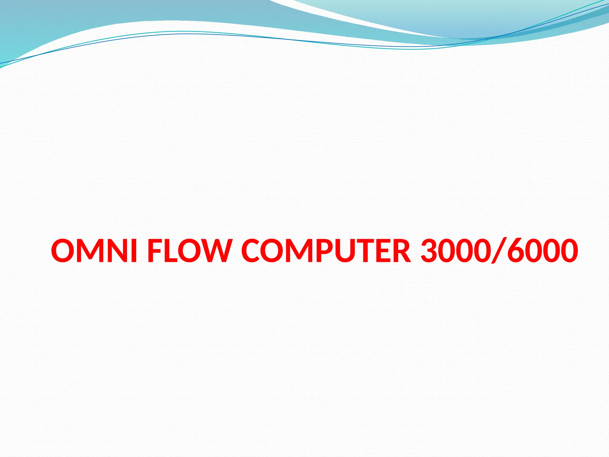
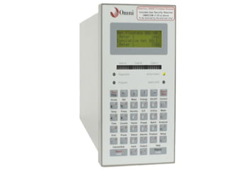
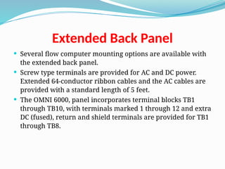
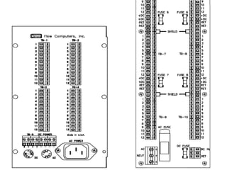
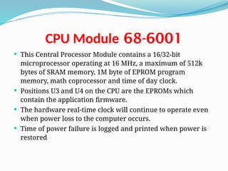
OMNI FLOW COMPUTER 3000/6000
INTRODUCTION
 About the Flow Computer Applications
 OMNI 6000 and OMNI 3000 Flow Computers are integral into the
majority of liquid and gas flow
 measurement and control systems. The current firmware revisions of
OMNI 6000/OMNI 3000 Flow Computers are:
 20/24: Turbine/Positive Displacement/Coriolis Liquid Flow
Metering Systems with K Factor Linearization (US/metric units)
 21/25: Orifice/Differential Pressure Liquid Flow Metering Systems
(US/metric units)
 22/26: Turbine/Positive Displacement Liquid Flow Metering
Systems with Meter Factor Linearization (US/metric units)
 23/27: Orifice/Turbine Gas Flow Metering Systems (US/metric units)
INTRODUCTION
 Manual Structure
 The User Manual comprises 4 volumes; each contained in separate
binding for easy manipulation. You will find a detailed table of
contents at the beginning of each volume.
 User Reference Documentation – The User Manual is structured
into four volumes.
 Volumes 1 and 2 are generic to all flow computer application
revisions.
 Volumes 3 and 4 are application specific.
 These have four versions each, published in separate documents
 i.e., one per application revision per volume.
 You will receive the version that corresponds to your application
revision.
INTRODUCTION
 Volume 1. System Architecture and Installation
 Volume 1 is generic to all applications and considers both US
and metric units. This volume describes:
 Basic hardware/software features
 Installation practices
 Calibration procedures
 Flow computer specifications
INTRODUCTION
 Volume 2. Basic Operation
 Volume 2 is application specific and is available in four separate
versions (one for each application revision).
 It covers the essential and routine tasks and procedures that may
be performed by the flow computer operator.
 Both US and metric units are considered.
 General computer-related features are described, such as:
 Basic hardware
 Software features
 Installation practices
 Calibration procedures
 Flow computer specifications
INTRODUCTION
 Volume 2. Basic Operation
 Overview of keypad functions
 Adjusting the display
 Clearing and viewing alarms
 Computer totalizing
 Printing and customizing reports
 The application-related topics may include:
 Batching operations
 Proving functions
 PID control functions
 Audit trail
 Other application specific functions
INTRODUCTION
 Volume 2. Basic Operation
 Depending on your application, some of these topics may not be
included in your specific documentation.
 An index of display variables and corresponding key press
sequences that are specific to your application are listed at the
end of each version of this volume.
INTRODUCTION
 Volume 3. Configuration and Advanced Operation
 Volume 3 is intended for the advanced user. It refers to
application specific topics and is available in four separate
versions (one for each application revision).
 This volume covers:
 Application overview
 Flow computer configuration data entry
 User-programmable functions
 Modbus Protocol implementation
 Flow equations and algorithms
INTRODUCTION
 Volume 4. Modbus Database Addresses and Index Numbers
 Volume 4 is intended for the system programmer (advanced
user).
 It comprises a descriptive list of database point assignments in
numerical order, within our firmware.
 This volume is application specific, for which there is one
version per application revision.
SYSTEM ARCHITECTURE AND
INSTALLATION
 Overview of Hardware and Software Features
 BASIC FEATURES - OMNI flow computers are applicable to liquid and gas
flow measurement, control and communication systems, and custody
transfer operations. It’s
 basic features are:
 32-bit processing, multi-tasking execution
 500 mSec calculation cycle
 Plug-in, assignable digital, serial and combination I/O modules
 Point-to-point digital transmitter interface
 14-bit A/Ds, temperature trimmed
 No I/O multiplexers, no potentiometers
 Photo-optical Isolation of each I/O point
 Meter pulse fidelity checking
SYSTEM ARCHITECTURE AND
INSTALLATION
 basic features are:
 Honeywell and Rosemount digital transmitter interface modules
 HART digital transmitter interface modules
 Ethernet communications module
 Dual LEDs indicate active/fused digital I/O
 Selectable digital I/O, individually fused
 Standard, field-proven firmware - no need for custom programming
 User-configurable control logic
 Up to 4 flow/pressure control loops
 User-configurable variables for displays and reports
 Data archive and report storage
 Modbus peer-to-peer communications to 38.4kbps for PLC/DCS
 Real-time dial-up for diagnostics
 Includes OMNICOM configuration software
OMNI Front Panel
Operator’s Panel
 LCD Display
 Electromechanical Totalizers
 Diagnostic and Program LEDs
 Active Alarm LED
 Alpha Shift LED
 Operator Keypad
Passive Backplane Mother Boards
 Passive backplane simply means that no active circuitry is
contained on it.
 The active circuitry is contained on the modules that plug into it.
 Mounted on the passive backplane are DIN standard connectors
which are bussed in two sections.
 The front section is a high performance, 16-bit bus which accepts
the Central Processor Module.
 The rear 8-bit I/O bus section comprises 10 connectors on the
OMNI 6000 and 4 on the OMNI 3000, which can accept any type
of I/O module manufactured by OMNI.
 The rearmost connector on both computers accepts the system
AC/DC power supply module.
 Dual ribbon cable assemblies (OMNI 6000) and a single ribbon
cable (OMNI 3000) connect the I/O connectors on the backplane
to the back panel terminals
OMNI 3000 Mother Board
OMNI 6000 Mother Board
Back Panel Terminal Board
 All signal I/O terminals and power connector/terminals are
available on the Back Panel.
 The AC power receptacle of the OMNI 6000 and OMNI 3000
Back Panel is an IEC 60320 C14 power inlet connector
assembly with an integral line-filter. The DC power
connector is a screw type terminal block.
 Both AC and DC fuse holders are also mounted on the Back
Panel for easy access. For detailed power requirements refer
to Input Power
 The OMNI 3000 terminal blocks are identified as TB1
through TB4, with terminals marked 1 through 12 for each
block.
Back Panel Terminal Board
 Each terminal block corresponds to the I/O module slot on
the Mother Board.
 The DC terminals are on TB5 marked plus (+) and minus (-)
 The OMNI 6000 terminal blocks are identified TB1 through
TB10 with terminals marked 1 through 12 for each block.
 These provide 120 circuit paths to the passive backplane.
 Each terminal block corresponds to the I/O module slot on
the Mother Board.
 The DC terminals are on TB11 marked plus (+) and minus (-)
Extended Back Panel
 Several flow computer mounting options are available with
the extended back panel.
 Screw type terminals are provided for AC and DC power.
Extended 64-conductor ribbon cables and the AC cables are
provided with a standard length of 5 feet.
 The OMNI 6000, panel incorporates terminal blocks TB1
through TB10, with terminals marked 1 through 12 and extra
DC (fused), return and shield terminals are provided for TB1
through TB8.
68-6001
CPU Module
 This Central Processor Module contains a 16/32-bit
microprocessor operating at 16 MHz, a maximum of 512k
bytes of SRAM memory, 1M byte of EPROM program
memory, math coprocessor and time of day clock.
 Positions U3 and U4 on the CPU are the EPROMs which
contain the application firmware.
 The hardware real-time clock will continue to operate even
when power loss to the computer occurs.
 Time of power failure is logged and printed when power is
restored
68-6001
CPU Module with SMT
RAM
 These two alternate CPU modules are equipped with Surface
Mount Technology for the RAM area.
 One CPU module with a daughter board containing U3 and
U4 EPROM’s, along with the surface mount RAM.
 The second version eliminates the daughter board placing
both EPROMs and SRAM directly onto the CPU
68-6201
CPU Module
 This CPU Module contains an updated processor, faster clock
and additional code and data memory space.
 The EPROM sockets have been replaced by Flash memory to
hold the application firmware
 CPU Jumper Settings:
 FLASH UPDATE
 Enabled – position for updating the Flash memory
 Disabled – position for Normal Operation
 WATCHDOG
 Out – for Factory use only
 In – for Normal Operation
68-6201
CPU Module
 Input/output (I/O) Modules
 OMNI Flow Computers utilize an I/O bus system. All I/O is
modular and plug-in for easy field maintenance and
replacement. I/O circuitry is also photo-optically isolated
from all field wiring which makes it relatively immune to
electrical noise and prevents damage to the electronics.
 Your OMNI Flow Computer has a combination of
different types of I/O modules:
 Digital (D) I/O Modules
 Serial (S) Modules
 Ethernet Modules
68-6201
CPU Module
 A and B Type Combo Modules
 E and E/D Type Combo Modules
 H and HV Type Combo Modules
 HART (HT and HM) Type Combo Modules
 SV Type Combo Modules
 Almost any combination of I/O mix can be accommodated in the
flow computer. The only limitations are the number of I/O
connectors (4 on OMNI 3000, 10 on OMNI 6000) and the number
of wires connecting them to the back panel field wiring
terminals (48 for OMNI 3000, 120 for OMNI 6000).
 The OMNI Flow Computer has a standard order in which the
modules are plugged into the Mother Board.
68-6201
CPU Module
 Photo-Optical Isolation
 The microprocessor circuitry is isolated via photo-optical devices from
all field wiring to prevent accidental damage to the electronics,
including that caused by static electricity. Photo-optical isolation also
inhibits electrical noise from inducing measurement errors.
Independent isolation of each process input provides high common-
mode rejection, allowing the user greater freedom when wiring
transmitter loops. Furthermore, it minimizes ground loop effects and
isolates and protects your flow computer from pipeline EMI and
transients.
 NOTE: Photo-Optical Isolation: Transducer signals are converted by the
LED into high frequency pulses of light. These are sensed by the photo-
transistor which passes the signal to the flow computer. Note that no
electrical connection exists between the transducers and the computer
circuits.
68-6201
CPU Module
 Digital I/O Modules
 NOTE: Some Digital I/O modules have 12 replaceable fuses; one fuse
for each I/O point. Other modules have electronic fuses that are tripped
when overloaded. They are automatically reset when the fault
condition is removed.
 Digital I/O modules provide inputs and outputs to control Provers,
Samplers, Injection pumps, and also provide remote totalizing. Each
digital module supplies 12 digital I/O points and each point may be
configured as an input or output. The OMNI 6000 can have a maximum
of two digital modules resulting in 24 digital I/O points. The OMNI 3000
normally has one digital I/O Module. Earlier Digital I/O Modules have
twelve ¼ amp fuses; one fuse for each I/O point. Recent SMT (Surface
Mount Technology) modules have circuitry for each channel trips if
overloaded and automatically resets when the overload is removed
(Figure 11).

68-6201
CPU Module
 NOTE: I/O Point LEDs: Along the edge of the Digital I/O module are 12
pairs of LEDs When a green LED is illuminated, the I/O point is active
and either receiving or sending pulses. The other LED is white in
appearance but illuminates red. A red LED indicates that either a fuse
is blown, on earlier modules or the I/O point is detecting an incorrect
input or output.
 IRQ, (Interrupt request) jumpers are provided on digital I/O modules
for interfacing to pipe prover detector switches. This feature applies
only to liquid measurement applications.
 These jumpers are only used to configure digital I/O point 1 or digital
I/O point 2 on module D1. All IRQ jumpers should be removed from D2
if a D2 module is installed
68-6201
CPU Module
 SMT Digital Module (68-6211)
 This current version of the Digital Module 68-6211 (Figure 13 and 14)
has the same number of digital I/O points available as the 68-6011
module (Figure 18). The only difference is that SMT (Surface Mount
Technology) modules have circuitry for each channel that trips when
overloaded. They automatically reset when the overload is removed.
An address jumper on the module allows the user to configure as
either a D1 or D2 module.
 NOTE: If using both a D1 and D2 module make sure the jumpers JP1
and JP2 on the D2 module are removed. I/O Point LEDs: Along the edge
of the digital I/O module are 12 pairs of LEDs When a green LED is
illuminated, the I/O point is active and either receiving or sending
pulses. The other LED is white in appearance but illuminates red. A red
LED indicates that either a fuse is blown, on earlier modules or the I/O
point is detecting an incorrect input or output.
68-6201
CPU Module
 Serial Communication Modules
 NOTE: Up to 12 flow computers and/or other compatible serial devices
can be multi-dropped using OMNI’s proprietary RS-232-C serial port.
Sixteen devices may be connected when using the RS-485 2-wire mode
and 32 devices can be connected when using RS-485 4 wire mode.
Typically, one serial I/O module is used on the OMNI 3000, providing
two ports. A maximum of three serial modules can be installed in the
OMNI 6000, providing six ports.
 Multivariable Transmitting Devices - In addition to the Serial I/O
Module # 68- 6205, the flow computer must also have an SV Module to
communicate with multivariable transmitters. This serial module must
be jumpered to use IRQ 3 when used in combination with an SV
Module. Without an SV Module, the jumper is placed in the IRQ 2
position. The SV Module can only be used with this serial module (68-
6205) and is not compatible with the Serial I/O Module # 68-6005.
68-6201
CPU Module
 RS-232/485 Serial I/O Module Model # 68-6205
 Serial I/O Module # 68-6205 is capable of handling two
communications ports Each serial communication port is individually
optically isolated for maximum common-mode and noise rejection
(Figure 19). Although providing RS-232C signal levels, the tri-state
output design allows multiple flow computers to share one serial link.
Communication parameters such as baud rate, stop bits and parity
settings are software selectable. In addition to RS-232, jumper
selections have been provided on each port to allow selection of RS-485
format. With this option, a total of two RS-485 ports are available on
 The RS-232/485 Module has been designed so that RS-232 or RS-485
communications standards can be selected by placement of 16-pin
resistor networks into the correct blocks. Figure 20 shows the locations
of blocks JB4, JB5, JB6 for Port #1, and JB1, JB2, JB3 for Port #2 for each
format. Note that the label settings in use are actually covered up by
the resistor networks. each module.
68-6201
CPU Module
 Process I/O Combination Modules
 Meter run instrumentation utilize plug-in process I/O “combo”
modules which include all necessary analog/digital (A/D) converters
and control circuitry. User selection of process I/O is available with
“combo” modules that can be a mix of meter pulse, frequency
densitometer, 4-20 mA, 4-wire 100 ohm RTD inputs, and 4-20 mA
outputs.
 All process measurements such as temperature, pressure, density, and
flow are input via these process I/O combo modules. Each module will
handle 4 inputs of a variety of signal types and provides one or two 4-
20 mA analog outputs (except the SV Module which has six 4-20 mA
outputs).
68-6201
CPU Module
 Process I/O Combination Modules
 Nine types of combo I/O modules are available: A, B, E, E/D, H, HV, HT,
HM and SV. All modules accept analog and pulse frequency type inputs,
except for the H and HV modules that interface digitally with
Honeywell Smart Transmitters, the HT and HM modules that interface
digitally with HART transmitters, and the SV module that interface
serially with RS-485 compatible multivariable transmitters.
 Except for the position of configuration jumpers that select the type
and address of each module, the A and B module types use identical I/O
boards, and also the E and E/D modules use identical boards.
Power Supply
 The OMNI Flow Computer can be AC or DC powered. Presently OMNI
offers the 6218 Universal PSU. The 6218 Power Supply can operate
between 90 and 264VAC input without any adjustments. See section 3.2
Input Power for detailed power information.
 The maximum system configuration of the OMNI is 24 process inputs,
18 process outputs are possible (if an SV-module is installed), 24 digital
I/O points, and 6* serial I/O channels. This Equipment dissipates
approximately 24 Watts. This causes an internal temperature of 15‫؛‬F
(8.33 C) over the ambient. The unit should not be mounted
Power Supply
 Model 68-6118 Power Supply
 All analog and digital circuits within the flow computer are powered
from a 5-volt switching regulator located on the power supply module.
This is located in the rear most connector on the computer backplane.
The DC power which supplies the switching regulator either comes
directly from the DC terminals on the Back Panel of the flow computer
(22-26 VDC) or by rectifying the output of the integral 120 VAC (230
VAC) 36VA transformer. Regulated 5-volt power is monitored by a 3-4
second shutdown circuit located on the 6118 power supply module.
When external power is applied to the computer, there will be a delay
of 3 to 4 seconds before the unit powers-up. If the 5VDC supply is short-
circuited, the supply will be shut-down and will attempt to restart in 3-
4 seconds.
Power Supply
 Model 68-6218 Power Supply
 All analog and digital circuits within the flow computer are powered
from a 5-volt switching regulator module located on the power supply
module. This is located in the rear most connector on the computer
backplane. The DC power which supplies the switching regulator
either comes directly from the DC terminals on the Back Panel of the
flow computer (22-26 VDC) or by a voltage converter that changes the
90 – 264 VAC to 24VDC. Regulated 5-volt power has a “soft-start” circuit
that allows the 5V to come up in approximately 150 milliseconds.
When external power is applied to the computer there will be a delay
of 150 milliseconds before the unit powers-up. If the 5VDC supply is
short-circuited the supply will be shut-down and will attempt to restart
when the short circuit no longer exists.
Firmware and Software
 OMNI Flow Computers are supplied with pre-programmed
firmware and PC configuration software which permit a single unit
to perform a great diversity of combined flow measurement tasks,
such as:
 Multiple Meter Run Totalizing, Batching, Proving, and Data Archiving
 Flow and Sampler Control
 Direct Interface to Gas Chromatographs and Smart/Multivariable
Transmitters
 Selectable Communications Protocols to Directly Interface to DCS, PLC
and SCADA Host Systems
 The flow computer database numbers thousands of data points
and provides the tightest communications coupling yet between
SCADA and the metering system.
Firmware and Software
 Interrupt-Driven CPU
 This is a very important aspect to firmware. It provides for a multi-
tasking environment in which priority tasks can be undertaken
concurrently with unrelated activity. This provides for high-speed
digital signals to be output at the same time as measurement
computations and serial communications to a printer or host
computer, without degradation in speed or tasking.
 All custody transfer measurement programs are stored in EPROM or
Flash Memory. This prevents damage due to electrical noise, or
tampering with the integrity of calculation specifications. SRAM
programming can also be accommodated.
Firmware and Software
 Cycle Time
 All time-critical measurement functions are performed by the flow
computer every 500 mSec. This provides greater accuracy of
measurement calculations and permits a faster response by pipeline
operations in critical control functions, such as opening or closing
valves.
 On-line Diagnostics and Calibration
 Extensive diagnostic software is built into the system which allows the
technician to locally or remotely debug a possible problem without
interrupting on-line measurement. Calibration of analog signals is
performed through the keypad and software. The system has only two
potentiometers, both of which are on the power supply and are factory
set and need no adjustment.
Firmware and Software
 PC Communications Interface
 The wide use of PCs and video display units makes it possible to
provide software for offline/ on-line access to measurement,
configuration and calibration data. Collection of historical reports,
including alarms, interval reports of any time sequence, liquid batch
and prove reports, and full remote technical intervention capabilities
are also provided.
 OMNICOM Configuration PC Software
 On-line or off-line configuration of your OMNI Flow Computer is
possible using a PC capable of running the OMNICOM program

supplied with your flow computer. This powerful software allows you
to copy modify and save to disk entire configurations. The program
also allows you to print customized reports by inputting report
templates that are uploaded to the flow computer.
Initializing Your Flow Computer
 A processor reset signal is automatically generated when:
 Power is applied.
 The processor reset switch at the rear of the front panel is toggled.
 The watchdog timer fails to be reset by firmware every 100
milliseconds.
 The flow computer will perform a diagnostic check of all program
and random-access memory whenever any of the above events
occur.
Process Input/output Combination Module
Setup
 User selection of process I/O is available with “combo” cards that can be a mix of meter
pulse, frequency densitometer, 4-20mA, 4-wire 100 ohm RTD inputs, and fused 4-20mA
outputs.
 Combo Module Input Features The input characteristics of each combo module are as
follows:
 A Type: Each input can be 1-5v; 4-20mA. Inputs #1 and #2 also accept RTD. Inputs #3
and #4 also accept flow pulse signals.
 B Type: Inputs #1, #2 & #3 can be 1-5v; 4-20mA. Inputs #1 and #2 also accept RTD. Input
#3 also accepts flow pulses and Input #4 is fixed as a frequency density input.
 E/D Type: Inputs #1 and #2 can be 1-5v; 4-20mA and RTD. Inputs #3 and #4 are
frequency density.
 E Type: Inputs #1 and #2 can be 1-5v; 4-20mA and RTD. Inputs #3 and #4 accept flow
pulses.
 H Type: All inputs are Honeywell DE Protocol.
 HV Type: All inputs are Honeywell Multivariable DE Protocol.
 HT/HM Type: Four HART FSK Networks.
 SV Type: Each port (#1 and #2) is capable of RS-485 multi-drop to various
multivariable transmitters.
Process Input/output Combination Module
Setup
 All process measurement signals are input via the process I/O combination (or
“combo”) modules plugged into the backplane of the computer. There currently are 9
types of combo modules available: A, B, E, E/D, H, HV, HT, HM and SV types. The 9
types of modules are actually manufactured using only 6 types of printed circuit
modules. The first can be configured as either an A or B Module; the second is used
for an E or E/D Module; the third is used for an H or HV Module; the fourth for an HT
module; the fifth for an HM module and the sixth is an SV module.
 Features of the I/O Combo Modules
 Each combo module (except the SV Module) will handle 4 inputs of a variety of signal
types and provides one or two 4-20 mA analog outputs. The SV Module has two ports
and six 4-20 mA analog outputs. Only the E Combo Module has Level A pulse fidelity
checking and double chronometry proving capabilities. The input/output capabilities
and some of the features of the combo modules are expressed in Table
Features of the I/O Combo Modules
 Setting the Address of the Combo Modules
 Jumpers are provided on each combo module that allows the user to select the
address needed to configure the module. Changing the firmware functions of
the module is also done by moving the appropriate jumper; i.e., A or B Type, E
or E/D, H or HV Type.
 Hardware Analog Configuration Jumpers
 Other jumpers are provided on each module that select the correct hardware
circuits needed for the type of signal that each input channel will accept. This
allows the same basic hardware module to accept signals such as 4-20 mA, 1-5
VDC, or 100ohm RTD probes as well as voltage or current pulses from a turbine,
PD meter or digital densitometer.
Features of the I/O Combo Modules
 Process I/O Combo Module Addresses Versus Physical I/O Points
 A flow computer will usually have several combo modules installed depending
on the number of flow meter runs to be measured. If for example, two A
modules, two B modules, one E/D module and one E modules were installed,
they would normally be numbered A1, A2, B1, B2, E/D1 and E1. Other address
combinations are acceptable (e.g.: A2, A3, B1, B4, E/D2 & E2) as long as each has
a unique identity. In the above example where six modules (A1, A2, B1, B2, E/D1
& E1) are installed, the physical I/O points are mapped as follows. (note that a B
module has only one analog output).
 That E/D modules come before the E modules To standardize, OMNI
recommends that combo modules should always be physically installed
starting with the lowest number A Type Module in I/O Slot #5 (Slot #3 in
OMNI 3000) as shown in Table 3, with additional modules being installed in
ascending order towards Slot #10 (Slot #4 in OMNI 3000).
Assigning Specific Signal Inputs
The OMNI factory pre-assigns the physical I/O points of each flow computer based
on
information supplied at time of order. This configuration information is stored in
battery
backed-up static CMOS RAM. If you wish to change or add to these assignments,
refer to the
section ‘Program Setup’ in Volume 3, Chapter 2 “Flow Computer
Configuration” and follow
these basic rules:
 Digital densitometer signals can only be assigned to the fourth channel of each
B Type Combo Module, or the third and fourth channel of each E/D Module.
 RTD signals can only be assigned to the first or second channel of each A, B, E/D
or E combo module. Whenever possible, avoid using the second RTD excitation
current source of an A Type Combo Module as this makes the second 4-20 mA
The A and B Combo I/O Modules
 All 4 process inputs can accept analog input voltages which are first
buffered with a 1 megohm input buffer, and then converted to pulse
frequencies using precision voltage-to frequency converters. With 2
averaged 500 millisecond samples, analog conversion
 resolution is 14 binary bits. Linearity is typically ±0.01% and the
temperature coefficient is trimmed to better than ±10 PPM/ F. Current

inputs such as 4-20 mA are converted to 1-5 VDC by jumpering-in a 250
ohm precision shunt resistor.
The A Type Combo I/O Module
The B Type Combo I/O Module
 You will need either a B Type Combo Module or E/D Type Combo
Module when using digital densitometers connected to the flow
computer. With a B Type Combo Module, Analog Output #2 is never
available because the periodic time function uses the internal timer
counter that is normally used to generate the second analog output.
 The B Type Combo Module (Figure 25 and 26) also handles 4 process
inputs but Input Channel # 4 is now used to measure the periodic time
of a digital densitometer. On the B module, Input Channel # 4 is always
jumpered as a frequency input. Signal coupling can be AC or DC with
trigger threshold adjustable for 1.6 or 3.5 Vpp sensitivity. Each module
is connected to the back panel terminal blocks via 12 wires on the
ribbon cables. The actual terminal block used depends upon which
backplane connector (?) the module is plugged into
The E/D and E Combo Modules
 The E/D and E combo I/O modules described below either use through-
hole technology components (P/N 68-6008), or surface mount
technology (SMT) components (P/N 68-6208) Modules manufactured
using either technology have similar performance and functionality.
 The hardware of E/D and E Type Combo Modules are similar to that of
the A and B Type Combo Modules (discussed previously) except these
modules provide only 2 analog input channels (1 and 2). These inputs
can be configured by jumpers for 1-5 volt, 4-20 mA or 4-wire RTDs. The
remaining two inputs (channels 3 and 4) are pulse inputs that can be
used to input flowmeter pulses or densitometer pulse signals. The
module hardware can also be configured by the application software
to provide “Level A Pulse Fidelity Checking” on the two pulse input
channels. Two 4-20 mA analog outputs are always available on the E/D
and E Type Combo Modules.
The E/D Type Combo I/O Module
 The E/D Type Combo Module is simply an E Type Combo Module with
the JPD jumper IN on the 6008 (in the ‘E/D’ position on the 6208)
Figures 27 and 28. Input Channels 1 and 2 are analog input channels
that are configured by jumpers for 1-5 volt, 4-20 mA, or 4-wire RTDs.
Input Channels 3 and 4 are always configured to measure periodic
time. They accept pulse signals from digital densitometers. Each
module is connected to the back panel terminal blocks via 12 wires on
the ribbon cables. The actual terminal numbers used depend upon
which backplane connector (?) the module is plugged into (Table ).
The E Type Combo I/O Module
 The E Type Combo Module uses the same PCB as the E/D Combo
Module. Jumper JPD is OUT on the 6008 (in the ‘E’ position on the 6208).
Double chronometry timers are provided in this module configuration,
allowing either pulse train (channel 3 or 4 on the module) to be
proved. Input Channels 3 and 4 must be used to input flowmeter
pulses. Input Channels 1 and 2 are analog input channels that are
configured by jumpers for 1-5 volt, 4-20 mA, or 4- wire RTDs. Both RTD
excitation current sources are always available. Each module is
connected to the back panel terminal blocks via 12 wires on the ribbon
cables. The actual terminal numbers used depend upon which
backplane connector (?) the module is plugged into (Table ).
The H Type Combo I/O Module
 The H Type Combo Module (Figure 29) is a special module that is used
to communicate with Honeywell field transmitters using the
Honeywell ‘DE Protocol’. It can communicate with up to 4 Honeywell
Smart Transmitters. It operates on a point-to-point basis. Honeywell
Model ST3000 temperature, pressure and differential pressure
transmitters are compatible. Transmitters operating in the ‘analog
mode’ are automatically given a ‘wake-up pulse’ and switched into the
‘DE’ Mode as soon as they are connected and assigned a meter run
function.
 Two analog outputs are always available on this module. Each module
is connected to the back panel terminal blocks via 12 wires on the
ribbon cables. The actual terminal numbers used depend upon which
backplane connector (?) the module is plugged into (Table ).
The SV Type Combo I/O Module
 The SV Type Combo Module (Figure) has two RS-485 serial ports that
are used to communicate with devices such as Rosemount 3095

multivariable transmitters using Modbus Protocol. The module also
has six 4-20 mA outputs (Table). Dual LEDs on each port provide status
of the communications.
 NOTE: SV Modules and Other Combo Module Types: The flow
computer can handle only
 two SV Modules and three other A, B, E/D, E or H I/O Combo Modules.
An HV module can also be installed in lieu of one of these I/O combo
modules. Reference Tech Bulletin # 980501
The HT / HM HART Module
 The HT/HM HART Module (Figure) is used to interface to HART devices
using the HART FSK protocol. The Module has four independent HART FSK
networks along with two analog outputs. The HT Module is used for point
to point communications and can support four single variable devices per
network. The HM Module is used for multi-drop configurations or multi-
variable sensors.
 NOTE: HT/HM HART Modules Types: The flow computer can handle up
to four HT/HM
 modules and can be installed with any other I/O modules except the H and
HV. See Technical Bulletin 090003 (52-0000-0019) for additional information
on the HT/HM Modules. Two analog outputs are always available on this
module. Each module is connected to the back panel terminal blocks via 12
wires on the ribbon cables. The actual terminal numbers used depend
upon which backplane connector (?) the module is plugged into (Table).
OMNI Flow Computer 3000,6000 hardware configuration.pptx

OMNI Flow Computer 3000,6000 hardware configuration.pptx

  • 1.
  • 3.
    INTRODUCTION  About theFlow Computer Applications  OMNI 6000 and OMNI 3000 Flow Computers are integral into the majority of liquid and gas flow  measurement and control systems. The current firmware revisions of OMNI 6000/OMNI 3000 Flow Computers are:  20/24: Turbine/Positive Displacement/Coriolis Liquid Flow Metering Systems with K Factor Linearization (US/metric units)  21/25: Orifice/Differential Pressure Liquid Flow Metering Systems (US/metric units)  22/26: Turbine/Positive Displacement Liquid Flow Metering Systems with Meter Factor Linearization (US/metric units)  23/27: Orifice/Turbine Gas Flow Metering Systems (US/metric units)
  • 4.
    INTRODUCTION  Manual Structure The User Manual comprises 4 volumes; each contained in separate binding for easy manipulation. You will find a detailed table of contents at the beginning of each volume.  User Reference Documentation – The User Manual is structured into four volumes.  Volumes 1 and 2 are generic to all flow computer application revisions.  Volumes 3 and 4 are application specific.  These have four versions each, published in separate documents  i.e., one per application revision per volume.  You will receive the version that corresponds to your application revision.
  • 5.
    INTRODUCTION  Volume 1.System Architecture and Installation  Volume 1 is generic to all applications and considers both US and metric units. This volume describes:  Basic hardware/software features  Installation practices  Calibration procedures  Flow computer specifications
  • 6.
    INTRODUCTION  Volume 2.Basic Operation  Volume 2 is application specific and is available in four separate versions (one for each application revision).  It covers the essential and routine tasks and procedures that may be performed by the flow computer operator.  Both US and metric units are considered.  General computer-related features are described, such as:  Basic hardware  Software features  Installation practices  Calibration procedures  Flow computer specifications
  • 7.
    INTRODUCTION  Volume 2.Basic Operation  Overview of keypad functions  Adjusting the display  Clearing and viewing alarms  Computer totalizing  Printing and customizing reports  The application-related topics may include:  Batching operations  Proving functions  PID control functions  Audit trail  Other application specific functions
  • 8.
    INTRODUCTION  Volume 2.Basic Operation  Depending on your application, some of these topics may not be included in your specific documentation.  An index of display variables and corresponding key press sequences that are specific to your application are listed at the end of each version of this volume.
  • 9.
    INTRODUCTION  Volume 3.Configuration and Advanced Operation  Volume 3 is intended for the advanced user. It refers to application specific topics and is available in four separate versions (one for each application revision).  This volume covers:  Application overview  Flow computer configuration data entry  User-programmable functions  Modbus Protocol implementation  Flow equations and algorithms
  • 10.
    INTRODUCTION  Volume 4.Modbus Database Addresses and Index Numbers  Volume 4 is intended for the system programmer (advanced user).  It comprises a descriptive list of database point assignments in numerical order, within our firmware.  This volume is application specific, for which there is one version per application revision.
  • 11.
    SYSTEM ARCHITECTURE AND INSTALLATION Overview of Hardware and Software Features  BASIC FEATURES - OMNI flow computers are applicable to liquid and gas flow measurement, control and communication systems, and custody transfer operations. It’s  basic features are:  32-bit processing, multi-tasking execution  500 mSec calculation cycle  Plug-in, assignable digital, serial and combination I/O modules  Point-to-point digital transmitter interface  14-bit A/Ds, temperature trimmed  No I/O multiplexers, no potentiometers  Photo-optical Isolation of each I/O point  Meter pulse fidelity checking
  • 12.
    SYSTEM ARCHITECTURE AND INSTALLATION basic features are:  Honeywell and Rosemount digital transmitter interface modules  HART digital transmitter interface modules  Ethernet communications module  Dual LEDs indicate active/fused digital I/O  Selectable digital I/O, individually fused  Standard, field-proven firmware - no need for custom programming  User-configurable control logic  Up to 4 flow/pressure control loops  User-configurable variables for displays and reports  Data archive and report storage  Modbus peer-to-peer communications to 38.4kbps for PLC/DCS  Real-time dial-up for diagnostics  Includes OMNICOM configuration software
  • 13.
  • 14.
    Operator’s Panel  LCDDisplay  Electromechanical Totalizers  Diagnostic and Program LEDs  Active Alarm LED  Alpha Shift LED  Operator Keypad
  • 16.
    Passive Backplane MotherBoards  Passive backplane simply means that no active circuitry is contained on it.  The active circuitry is contained on the modules that plug into it.  Mounted on the passive backplane are DIN standard connectors which are bussed in two sections.  The front section is a high performance, 16-bit bus which accepts the Central Processor Module.  The rear 8-bit I/O bus section comprises 10 connectors on the OMNI 6000 and 4 on the OMNI 3000, which can accept any type of I/O module manufactured by OMNI.  The rearmost connector on both computers accepts the system AC/DC power supply module.  Dual ribbon cable assemblies (OMNI 6000) and a single ribbon cable (OMNI 3000) connect the I/O connectors on the backplane to the back panel terminals
  • 17.
  • 18.
  • 19.
    Back Panel TerminalBoard  All signal I/O terminals and power connector/terminals are available on the Back Panel.  The AC power receptacle of the OMNI 6000 and OMNI 3000 Back Panel is an IEC 60320 C14 power inlet connector assembly with an integral line-filter. The DC power connector is a screw type terminal block.  Both AC and DC fuse holders are also mounted on the Back Panel for easy access. For detailed power requirements refer to Input Power  The OMNI 3000 terminal blocks are identified as TB1 through TB4, with terminals marked 1 through 12 for each block.
  • 20.
    Back Panel TerminalBoard  Each terminal block corresponds to the I/O module slot on the Mother Board.  The DC terminals are on TB5 marked plus (+) and minus (-)  The OMNI 6000 terminal blocks are identified TB1 through TB10 with terminals marked 1 through 12 for each block.  These provide 120 circuit paths to the passive backplane.  Each terminal block corresponds to the I/O module slot on the Mother Board.  The DC terminals are on TB11 marked plus (+) and minus (-)
  • 22.
    Extended Back Panel Several flow computer mounting options are available with the extended back panel.  Screw type terminals are provided for AC and DC power. Extended 64-conductor ribbon cables and the AC cables are provided with a standard length of 5 feet.  The OMNI 6000, panel incorporates terminal blocks TB1 through TB10, with terminals marked 1 through 12 and extra DC (fused), return and shield terminals are provided for TB1 through TB8.
  • 24.
    68-6001 CPU Module  ThisCentral Processor Module contains a 16/32-bit microprocessor operating at 16 MHz, a maximum of 512k bytes of SRAM memory, 1M byte of EPROM program memory, math coprocessor and time of day clock.  Positions U3 and U4 on the CPU are the EPROMs which contain the application firmware.  The hardware real-time clock will continue to operate even when power loss to the computer occurs.  Time of power failure is logged and printed when power is restored
  • 26.
    68-6001 CPU Module withSMT RAM  These two alternate CPU modules are equipped with Surface Mount Technology for the RAM area.  One CPU module with a daughter board containing U3 and U4 EPROM’s, along with the surface mount RAM.  The second version eliminates the daughter board placing both EPROMs and SRAM directly onto the CPU
  • 28.
    68-6201 CPU Module  ThisCPU Module contains an updated processor, faster clock and additional code and data memory space.  The EPROM sockets have been replaced by Flash memory to hold the application firmware  CPU Jumper Settings:  FLASH UPDATE  Enabled – position for updating the Flash memory  Disabled – position for Normal Operation  WATCHDOG  Out – for Factory use only  In – for Normal Operation
  • 30.
    68-6201 CPU Module  Input/output(I/O) Modules  OMNI Flow Computers utilize an I/O bus system. All I/O is modular and plug-in for easy field maintenance and replacement. I/O circuitry is also photo-optically isolated from all field wiring which makes it relatively immune to electrical noise and prevents damage to the electronics.  Your OMNI Flow Computer has a combination of different types of I/O modules:  Digital (D) I/O Modules  Serial (S) Modules  Ethernet Modules
  • 31.
    68-6201 CPU Module  Aand B Type Combo Modules  E and E/D Type Combo Modules  H and HV Type Combo Modules  HART (HT and HM) Type Combo Modules  SV Type Combo Modules  Almost any combination of I/O mix can be accommodated in the flow computer. The only limitations are the number of I/O connectors (4 on OMNI 3000, 10 on OMNI 6000) and the number of wires connecting them to the back panel field wiring terminals (48 for OMNI 3000, 120 for OMNI 6000).  The OMNI Flow Computer has a standard order in which the modules are plugged into the Mother Board.
  • 33.
    68-6201 CPU Module  Photo-OpticalIsolation  The microprocessor circuitry is isolated via photo-optical devices from all field wiring to prevent accidental damage to the electronics, including that caused by static electricity. Photo-optical isolation also inhibits electrical noise from inducing measurement errors. Independent isolation of each process input provides high common- mode rejection, allowing the user greater freedom when wiring transmitter loops. Furthermore, it minimizes ground loop effects and isolates and protects your flow computer from pipeline EMI and transients.  NOTE: Photo-Optical Isolation: Transducer signals are converted by the LED into high frequency pulses of light. These are sensed by the photo- transistor which passes the signal to the flow computer. Note that no electrical connection exists between the transducers and the computer circuits.
  • 34.
    68-6201 CPU Module  DigitalI/O Modules  NOTE: Some Digital I/O modules have 12 replaceable fuses; one fuse for each I/O point. Other modules have electronic fuses that are tripped when overloaded. They are automatically reset when the fault condition is removed.  Digital I/O modules provide inputs and outputs to control Provers, Samplers, Injection pumps, and also provide remote totalizing. Each digital module supplies 12 digital I/O points and each point may be configured as an input or output. The OMNI 6000 can have a maximum of two digital modules resulting in 24 digital I/O points. The OMNI 3000 normally has one digital I/O Module. Earlier Digital I/O Modules have twelve ¼ amp fuses; one fuse for each I/O point. Recent SMT (Surface Mount Technology) modules have circuitry for each channel trips if overloaded and automatically resets when the overload is removed (Figure 11). 
  • 36.
    68-6201 CPU Module  NOTE:I/O Point LEDs: Along the edge of the Digital I/O module are 12 pairs of LEDs When a green LED is illuminated, the I/O point is active and either receiving or sending pulses. The other LED is white in appearance but illuminates red. A red LED indicates that either a fuse is blown, on earlier modules or the I/O point is detecting an incorrect input or output.  IRQ, (Interrupt request) jumpers are provided on digital I/O modules for interfacing to pipe prover detector switches. This feature applies only to liquid measurement applications.  These jumpers are only used to configure digital I/O point 1 or digital I/O point 2 on module D1. All IRQ jumpers should be removed from D2 if a D2 module is installed
  • 38.
    68-6201 CPU Module  SMTDigital Module (68-6211)  This current version of the Digital Module 68-6211 (Figure 13 and 14) has the same number of digital I/O points available as the 68-6011 module (Figure 18). The only difference is that SMT (Surface Mount Technology) modules have circuitry for each channel that trips when overloaded. They automatically reset when the overload is removed. An address jumper on the module allows the user to configure as either a D1 or D2 module.  NOTE: If using both a D1 and D2 module make sure the jumpers JP1 and JP2 on the D2 module are removed. I/O Point LEDs: Along the edge of the digital I/O module are 12 pairs of LEDs When a green LED is illuminated, the I/O point is active and either receiving or sending pulses. The other LED is white in appearance but illuminates red. A red LED indicates that either a fuse is blown, on earlier modules or the I/O point is detecting an incorrect input or output.
  • 40.
    68-6201 CPU Module  SerialCommunication Modules  NOTE: Up to 12 flow computers and/or other compatible serial devices can be multi-dropped using OMNI’s proprietary RS-232-C serial port. Sixteen devices may be connected when using the RS-485 2-wire mode and 32 devices can be connected when using RS-485 4 wire mode. Typically, one serial I/O module is used on the OMNI 3000, providing two ports. A maximum of three serial modules can be installed in the OMNI 6000, providing six ports.  Multivariable Transmitting Devices - In addition to the Serial I/O Module # 68- 6205, the flow computer must also have an SV Module to communicate with multivariable transmitters. This serial module must be jumpered to use IRQ 3 when used in combination with an SV Module. Without an SV Module, the jumper is placed in the IRQ 2 position. The SV Module can only be used with this serial module (68- 6205) and is not compatible with the Serial I/O Module # 68-6005.
  • 41.
    68-6201 CPU Module  RS-232/485Serial I/O Module Model # 68-6205  Serial I/O Module # 68-6205 is capable of handling two communications ports Each serial communication port is individually optically isolated for maximum common-mode and noise rejection (Figure 19). Although providing RS-232C signal levels, the tri-state output design allows multiple flow computers to share one serial link. Communication parameters such as baud rate, stop bits and parity settings are software selectable. In addition to RS-232, jumper selections have been provided on each port to allow selection of RS-485 format. With this option, a total of two RS-485 ports are available on  The RS-232/485 Module has been designed so that RS-232 or RS-485 communications standards can be selected by placement of 16-pin resistor networks into the correct blocks. Figure 20 shows the locations of blocks JB4, JB5, JB6 for Port #1, and JB1, JB2, JB3 for Port #2 for each format. Note that the label settings in use are actually covered up by the resistor networks. each module.
  • 47.
    68-6201 CPU Module  ProcessI/O Combination Modules  Meter run instrumentation utilize plug-in process I/O “combo” modules which include all necessary analog/digital (A/D) converters and control circuitry. User selection of process I/O is available with “combo” modules that can be a mix of meter pulse, frequency densitometer, 4-20 mA, 4-wire 100 ohm RTD inputs, and 4-20 mA outputs.  All process measurements such as temperature, pressure, density, and flow are input via these process I/O combo modules. Each module will handle 4 inputs of a variety of signal types and provides one or two 4- 20 mA analog outputs (except the SV Module which has six 4-20 mA outputs).
  • 48.
    68-6201 CPU Module  ProcessI/O Combination Modules  Nine types of combo I/O modules are available: A, B, E, E/D, H, HV, HT, HM and SV. All modules accept analog and pulse frequency type inputs, except for the H and HV modules that interface digitally with Honeywell Smart Transmitters, the HT and HM modules that interface digitally with HART transmitters, and the SV module that interface serially with RS-485 compatible multivariable transmitters.  Except for the position of configuration jumpers that select the type and address of each module, the A and B module types use identical I/O boards, and also the E and E/D modules use identical boards.
  • 49.
    Power Supply  TheOMNI Flow Computer can be AC or DC powered. Presently OMNI offers the 6218 Universal PSU. The 6218 Power Supply can operate between 90 and 264VAC input without any adjustments. See section 3.2 Input Power for detailed power information.  The maximum system configuration of the OMNI is 24 process inputs, 18 process outputs are possible (if an SV-module is installed), 24 digital I/O points, and 6* serial I/O channels. This Equipment dissipates approximately 24 Watts. This causes an internal temperature of 15‫؛‬F (8.33 C) over the ambient. The unit should not be mounted
  • 50.
    Power Supply  Model68-6118 Power Supply  All analog and digital circuits within the flow computer are powered from a 5-volt switching regulator located on the power supply module. This is located in the rear most connector on the computer backplane. The DC power which supplies the switching regulator either comes directly from the DC terminals on the Back Panel of the flow computer (22-26 VDC) or by rectifying the output of the integral 120 VAC (230 VAC) 36VA transformer. Regulated 5-volt power is monitored by a 3-4 second shutdown circuit located on the 6118 power supply module. When external power is applied to the computer, there will be a delay of 3 to 4 seconds before the unit powers-up. If the 5VDC supply is short- circuited, the supply will be shut-down and will attempt to restart in 3- 4 seconds.
  • 51.
    Power Supply  Model68-6118 Power Supply  All analog and digital circuits within the flow computer are powered from a 5-volt switching regulator located on the power supply module. This is located in the rear most connector on the computer backplane. The DC power which supplies the switching regulator either comes directly from the DC terminals on the Back Panel of the flow computer (22-26 VDC) or by rectifying the output of the integral 120 VAC (230 VAC) 36VA transformer. Regulated 5-volt power is monitored by a 3-4 second shutdown circuit located on the 6118 power supply module. When external power is applied to the computer, there will be a delay of 3 to 4 seconds before the unit powers-up. If the 5VDC supply is short- circuited, the supply will be shut-down and will attempt to restart in 3- 4 seconds.
  • 53.
    Power Supply  Model68-6218 Power Supply  All analog and digital circuits within the flow computer are powered from a 5-volt switching regulator module located on the power supply module. This is located in the rear most connector on the computer backplane. The DC power which supplies the switching regulator either comes directly from the DC terminals on the Back Panel of the flow computer (22-26 VDC) or by a voltage converter that changes the 90 – 264 VAC to 24VDC. Regulated 5-volt power has a “soft-start” circuit that allows the 5V to come up in approximately 150 milliseconds. When external power is applied to the computer there will be a delay of 150 milliseconds before the unit powers-up. If the 5VDC supply is short-circuited the supply will be shut-down and will attempt to restart when the short circuit no longer exists.
  • 55.
    Firmware and Software OMNI Flow Computers are supplied with pre-programmed firmware and PC configuration software which permit a single unit to perform a great diversity of combined flow measurement tasks, such as:  Multiple Meter Run Totalizing, Batching, Proving, and Data Archiving  Flow and Sampler Control  Direct Interface to Gas Chromatographs and Smart/Multivariable Transmitters  Selectable Communications Protocols to Directly Interface to DCS, PLC and SCADA Host Systems  The flow computer database numbers thousands of data points and provides the tightest communications coupling yet between SCADA and the metering system.
  • 56.
    Firmware and Software Interrupt-Driven CPU  This is a very important aspect to firmware. It provides for a multi- tasking environment in which priority tasks can be undertaken concurrently with unrelated activity. This provides for high-speed digital signals to be output at the same time as measurement computations and serial communications to a printer or host computer, without degradation in speed or tasking.  All custody transfer measurement programs are stored in EPROM or Flash Memory. This prevents damage due to electrical noise, or tampering with the integrity of calculation specifications. SRAM programming can also be accommodated.
  • 57.
    Firmware and Software Cycle Time  All time-critical measurement functions are performed by the flow computer every 500 mSec. This provides greater accuracy of measurement calculations and permits a faster response by pipeline operations in critical control functions, such as opening or closing valves.  On-line Diagnostics and Calibration  Extensive diagnostic software is built into the system which allows the technician to locally or remotely debug a possible problem without interrupting on-line measurement. Calibration of analog signals is performed through the keypad and software. The system has only two potentiometers, both of which are on the power supply and are factory set and need no adjustment.
  • 58.
    Firmware and Software PC Communications Interface  The wide use of PCs and video display units makes it possible to provide software for offline/ on-line access to measurement, configuration and calibration data. Collection of historical reports, including alarms, interval reports of any time sequence, liquid batch and prove reports, and full remote technical intervention capabilities are also provided.  OMNICOM Configuration PC Software  On-line or off-line configuration of your OMNI Flow Computer is possible using a PC capable of running the OMNICOM program  supplied with your flow computer. This powerful software allows you to copy modify and save to disk entire configurations. The program also allows you to print customized reports by inputting report templates that are uploaded to the flow computer.
  • 59.
    Initializing Your FlowComputer  A processor reset signal is automatically generated when:  Power is applied.  The processor reset switch at the rear of the front panel is toggled.  The watchdog timer fails to be reset by firmware every 100 milliseconds.  The flow computer will perform a diagnostic check of all program and random-access memory whenever any of the above events occur.
  • 62.
    Process Input/output CombinationModule Setup  User selection of process I/O is available with “combo” cards that can be a mix of meter pulse, frequency densitometer, 4-20mA, 4-wire 100 ohm RTD inputs, and fused 4-20mA outputs.  Combo Module Input Features The input characteristics of each combo module are as follows:  A Type: Each input can be 1-5v; 4-20mA. Inputs #1 and #2 also accept RTD. Inputs #3 and #4 also accept flow pulse signals.  B Type: Inputs #1, #2 & #3 can be 1-5v; 4-20mA. Inputs #1 and #2 also accept RTD. Input #3 also accepts flow pulses and Input #4 is fixed as a frequency density input.  E/D Type: Inputs #1 and #2 can be 1-5v; 4-20mA and RTD. Inputs #3 and #4 are frequency density.  E Type: Inputs #1 and #2 can be 1-5v; 4-20mA and RTD. Inputs #3 and #4 accept flow pulses.  H Type: All inputs are Honeywell DE Protocol.  HV Type: All inputs are Honeywell Multivariable DE Protocol.  HT/HM Type: Four HART FSK Networks.  SV Type: Each port (#1 and #2) is capable of RS-485 multi-drop to various multivariable transmitters.
  • 63.
    Process Input/output CombinationModule Setup  All process measurement signals are input via the process I/O combination (or “combo”) modules plugged into the backplane of the computer. There currently are 9 types of combo modules available: A, B, E, E/D, H, HV, HT, HM and SV types. The 9 types of modules are actually manufactured using only 6 types of printed circuit modules. The first can be configured as either an A or B Module; the second is used for an E or E/D Module; the third is used for an H or HV Module; the fourth for an HT module; the fifth for an HM module and the sixth is an SV module.  Features of the I/O Combo Modules  Each combo module (except the SV Module) will handle 4 inputs of a variety of signal types and provides one or two 4-20 mA analog outputs. The SV Module has two ports and six 4-20 mA analog outputs. Only the E Combo Module has Level A pulse fidelity checking and double chronometry proving capabilities. The input/output capabilities and some of the features of the combo modules are expressed in Table
  • 65.
    Features of theI/O Combo Modules  Setting the Address of the Combo Modules  Jumpers are provided on each combo module that allows the user to select the address needed to configure the module. Changing the firmware functions of the module is also done by moving the appropriate jumper; i.e., A or B Type, E or E/D, H or HV Type.  Hardware Analog Configuration Jumpers  Other jumpers are provided on each module that select the correct hardware circuits needed for the type of signal that each input channel will accept. This allows the same basic hardware module to accept signals such as 4-20 mA, 1-5 VDC, or 100ohm RTD probes as well as voltage or current pulses from a turbine, PD meter or digital densitometer.
  • 66.
    Features of theI/O Combo Modules  Process I/O Combo Module Addresses Versus Physical I/O Points  A flow computer will usually have several combo modules installed depending on the number of flow meter runs to be measured. If for example, two A modules, two B modules, one E/D module and one E modules were installed, they would normally be numbered A1, A2, B1, B2, E/D1 and E1. Other address combinations are acceptable (e.g.: A2, A3, B1, B4, E/D2 & E2) as long as each has a unique identity. In the above example where six modules (A1, A2, B1, B2, E/D1 & E1) are installed, the physical I/O points are mapped as follows. (note that a B module has only one analog output).  That E/D modules come before the E modules To standardize, OMNI recommends that combo modules should always be physically installed starting with the lowest number A Type Module in I/O Slot #5 (Slot #3 in OMNI 3000) as shown in Table 3, with additional modules being installed in ascending order towards Slot #10 (Slot #4 in OMNI 3000).
  • 67.
    Assigning Specific SignalInputs The OMNI factory pre-assigns the physical I/O points of each flow computer based on information supplied at time of order. This configuration information is stored in battery backed-up static CMOS RAM. If you wish to change or add to these assignments, refer to the section ‘Program Setup’ in Volume 3, Chapter 2 “Flow Computer Configuration” and follow these basic rules:  Digital densitometer signals can only be assigned to the fourth channel of each B Type Combo Module, or the third and fourth channel of each E/D Module.  RTD signals can only be assigned to the first or second channel of each A, B, E/D or E combo module. Whenever possible, avoid using the second RTD excitation current source of an A Type Combo Module as this makes the second 4-20 mA
  • 68.
    The A andB Combo I/O Modules  All 4 process inputs can accept analog input voltages which are first buffered with a 1 megohm input buffer, and then converted to pulse frequencies using precision voltage-to frequency converters. With 2 averaged 500 millisecond samples, analog conversion  resolution is 14 binary bits. Linearity is typically ±0.01% and the temperature coefficient is trimmed to better than ±10 PPM/ F. Current  inputs such as 4-20 mA are converted to 1-5 VDC by jumpering-in a 250 ohm precision shunt resistor.
  • 70.
    The A TypeCombo I/O Module
  • 75.
    The B TypeCombo I/O Module  You will need either a B Type Combo Module or E/D Type Combo Module when using digital densitometers connected to the flow computer. With a B Type Combo Module, Analog Output #2 is never available because the periodic time function uses the internal timer counter that is normally used to generate the second analog output.  The B Type Combo Module (Figure 25 and 26) also handles 4 process inputs but Input Channel # 4 is now used to measure the periodic time of a digital densitometer. On the B module, Input Channel # 4 is always jumpered as a frequency input. Signal coupling can be AC or DC with trigger threshold adjustable for 1.6 or 3.5 Vpp sensitivity. Each module is connected to the back panel terminal blocks via 12 wires on the ribbon cables. The actual terminal block used depends upon which backplane connector (?) the module is plugged into
  • 79.
    The E/D andE Combo Modules  The E/D and E combo I/O modules described below either use through- hole technology components (P/N 68-6008), or surface mount technology (SMT) components (P/N 68-6208) Modules manufactured using either technology have similar performance and functionality.  The hardware of E/D and E Type Combo Modules are similar to that of the A and B Type Combo Modules (discussed previously) except these modules provide only 2 analog input channels (1 and 2). These inputs can be configured by jumpers for 1-5 volt, 4-20 mA or 4-wire RTDs. The remaining two inputs (channels 3 and 4) are pulse inputs that can be used to input flowmeter pulses or densitometer pulse signals. The module hardware can also be configured by the application software to provide “Level A Pulse Fidelity Checking” on the two pulse input channels. Two 4-20 mA analog outputs are always available on the E/D and E Type Combo Modules.
  • 80.
    The E/D TypeCombo I/O Module  The E/D Type Combo Module is simply an E Type Combo Module with the JPD jumper IN on the 6008 (in the ‘E/D’ position on the 6208) Figures 27 and 28. Input Channels 1 and 2 are analog input channels that are configured by jumpers for 1-5 volt, 4-20 mA, or 4-wire RTDs. Input Channels 3 and 4 are always configured to measure periodic time. They accept pulse signals from digital densitometers. Each module is connected to the back panel terminal blocks via 12 wires on the ribbon cables. The actual terminal numbers used depend upon which backplane connector (?) the module is plugged into (Table ).
  • 84.
    The E TypeCombo I/O Module  The E Type Combo Module uses the same PCB as the E/D Combo Module. Jumper JPD is OUT on the 6008 (in the ‘E’ position on the 6208). Double chronometry timers are provided in this module configuration, allowing either pulse train (channel 3 or 4 on the module) to be proved. Input Channels 3 and 4 must be used to input flowmeter pulses. Input Channels 1 and 2 are analog input channels that are configured by jumpers for 1-5 volt, 4-20 mA, or 4- wire RTDs. Both RTD excitation current sources are always available. Each module is connected to the back panel terminal blocks via 12 wires on the ribbon cables. The actual terminal numbers used depend upon which backplane connector (?) the module is plugged into (Table ).
  • 86.
    The H TypeCombo I/O Module  The H Type Combo Module (Figure 29) is a special module that is used to communicate with Honeywell field transmitters using the Honeywell ‘DE Protocol’. It can communicate with up to 4 Honeywell Smart Transmitters. It operates on a point-to-point basis. Honeywell Model ST3000 temperature, pressure and differential pressure transmitters are compatible. Transmitters operating in the ‘analog mode’ are automatically given a ‘wake-up pulse’ and switched into the ‘DE’ Mode as soon as they are connected and assigned a meter run function.  Two analog outputs are always available on this module. Each module is connected to the back panel terminal blocks via 12 wires on the ribbon cables. The actual terminal numbers used depend upon which backplane connector (?) the module is plugged into (Table ).
  • 89.
    The SV TypeCombo I/O Module  The SV Type Combo Module (Figure) has two RS-485 serial ports that are used to communicate with devices such as Rosemount 3095  multivariable transmitters using Modbus Protocol. The module also has six 4-20 mA outputs (Table). Dual LEDs on each port provide status of the communications.  NOTE: SV Modules and Other Combo Module Types: The flow computer can handle only  two SV Modules and three other A, B, E/D, E or H I/O Combo Modules. An HV module can also be installed in lieu of one of these I/O combo modules. Reference Tech Bulletin # 980501
  • 92.
    The HT /HM HART Module  The HT/HM HART Module (Figure) is used to interface to HART devices using the HART FSK protocol. The Module has four independent HART FSK networks along with two analog outputs. The HT Module is used for point to point communications and can support four single variable devices per network. The HM Module is used for multi-drop configurations or multi- variable sensors.  NOTE: HT/HM HART Modules Types: The flow computer can handle up to four HT/HM  modules and can be installed with any other I/O modules except the H and HV. See Technical Bulletin 090003 (52-0000-0019) for additional information on the HT/HM Modules. Two analog outputs are always available on this module. Each module is connected to the back panel terminal blocks via 12 wires on the ribbon cables. The actual terminal numbers used depend upon which backplane connector (?) the module is plugged into (Table).