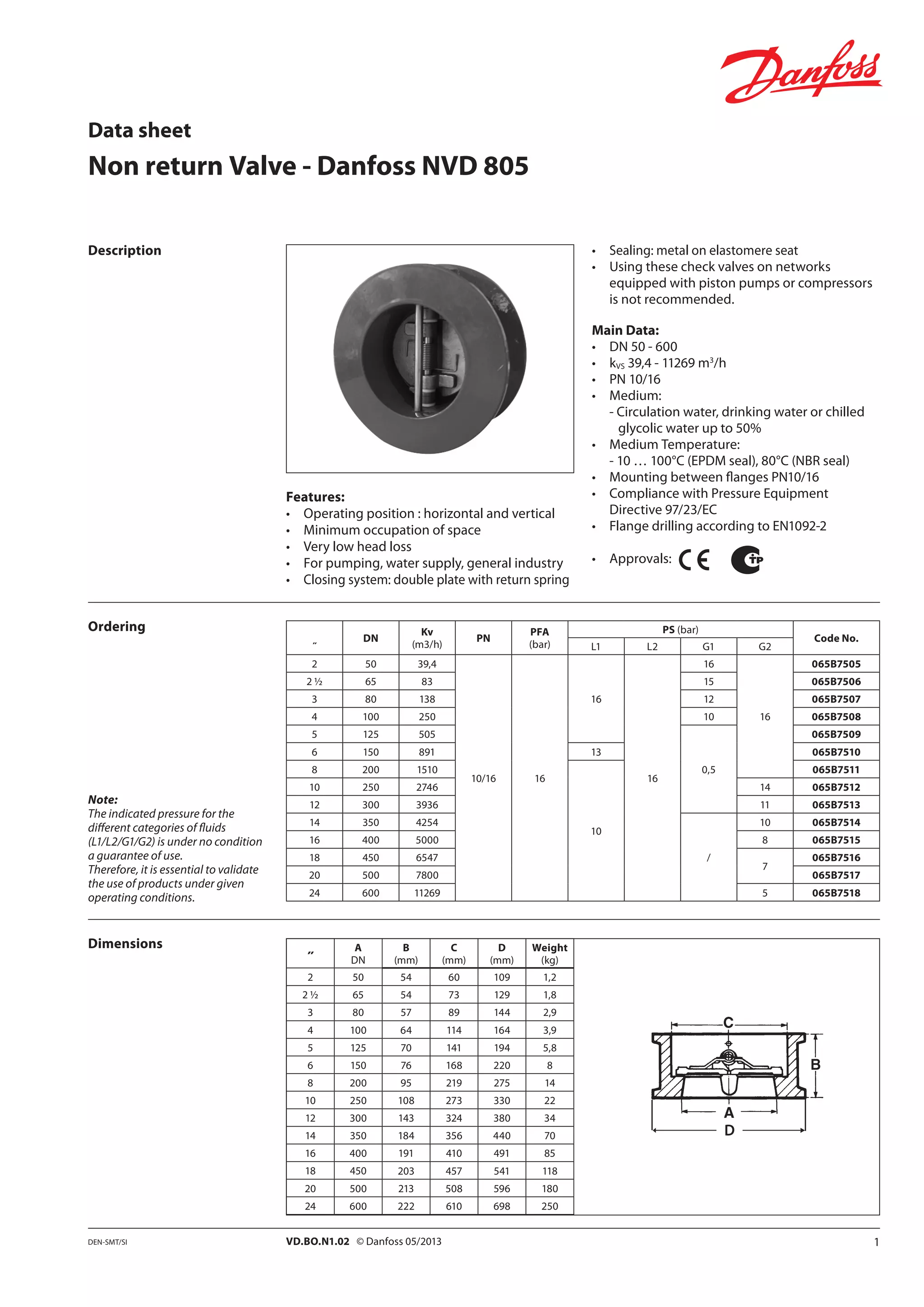
˝
A
DN
B
(mm)
C
(mm)
D
(mm)
Weight
(kg)
2 50 54 60 109 1,2
2 ½ 65 54 73 129 1,8
3 80 57 89 144 2,9
4 100 64 114 164 3,9
5 125 70 141 194 5,8
6 150 76 168 220 8
8 200 95 219 275 14
10 250 108 273 330 22
12 300 143 324 380 34
14 350 184 356 440 70
16 400 191 410 491 85
18 450 203 457 541 118
20 500 213 508 596 180
24 600 222 610 698 250
D
1VD.BO.N1.02 © Danfoss 05/2013DEN-SMT/SI
Non return Valve - Danfoss NVD 805
Features:
• 	 Operating position : horizontal and vertical
• 	 Minimum occupation of space
• 	 Very low head loss
• 	 For pumping, water supply, general industry
• 	 Closing system: double plate with return spring
Description
Ordering
Dimensions
Note:
The indicated pressure for the
different categories of fluids
(L1/L2/G1/G2) is under no condition
a guarantee of use.
Therefore, it is essential to validate
the use of products under given
operating conditions.
• 	 Sealing: metal on elastomere seat
• 	 Using these check valves on networks
equipped with piston pumps or compressors
is not recommended.
Main Data:
• 	 DN 50 - 600
• 	 kVS 39,4 - 11269 m3
/h
• 	 PN 10/16
• 	 Medium:
- Circulation water, drinking water or chilled
glycolic water up to 50%
• 	 Medium Temperature:
- 10 … 100°C (EPDM seal), 80°C (NBR seal)
• 	 Mounting between flanges PN10/16
• 	 Compliance with Pressure Equipment
Directive 97/23/EC
• 	 Flange drilling according to EN1092-2
• 	 Approvals:
˝
DN
Kv
(m3/h)
PN
PFA
(bar)
PS (bar)
Code No.
L1 L2 G1 G2
2 50 39,4
10/16 16
16
16
16
16
065B7505
2 ½ 65 83 15 065B7506
3 80 138 12 065B7507
4 100 250 10 065B7508
5 125 505
0,5
065B7509
6 150 891 13 065B7510
8 200 1510
10
065B7511
10 250 2746 14 065B7512
12 300 3936 11 065B7513
14 350 4254
/
10 065B7514
16 400 5000 8 065B7515
18 450 6547
7
065B7516
20 500 7800 065B7517
24 600 11269 5 065B7518
PED 97/23/CE
Data sheet
2 Produced by Danfoss A/S © 05/2013VD.BO.N1.02
Design
Headloss diagram
Pos. Description Material EURO ANSI
1
Casing DN50-150
DN200-300&400
*DN350&450-600
Cast iron + epoxy
Ductile iron + epoxy
Cast iron + epoxy
EN-GJL-250
EN-GJS-400.15
EN-GJL-250
ASTM A 48 35 B
ASTM A 536 65-45-12
ASTM A 48 35 B
2 Plates Aluminium bronze CuAl10Fe5Ni5 C95400
3
Seal DN50-300&400
DN350&450-600
EPDM
NBR (nitrile)
− −
4 Spring Stainless steel X5CrNiMo17-12-2 AISI 316
5
Steam DN50-300&400
DN350&450-600
Stainless steel
X3CrNiMo17-13-3
X5CrNi18-10
AISI 316
AISI 304
6 Bearing PTFE − −
7 Eye bolt DN>150 Steel XC15 − −
8 Plugs Brass − −
DN
Opening pressure
(mm) KV
(m3
/h)
ζ
˝
(mm)
2 50
Near 0
39,40 6,30
2 1/2 65 83,00 4,10
3 80 138,00 3,40
4 100 250,00 2,50
5 125 505,00 1,45
6 150 891,00 1,00
8 200 1510,0 1,10
10 250 2746,00 1,10
12 300 3936,00 1,10
14 350 4254,00 1,30
16 400 5000,00 1,60
18 450 6547,00 1,50
20 500 7800,00 1,60
24 600 11269,00 1,60
Data sheet	 Danfoss NVD 805
Direction for use :
• 	 Solid line : Valve completely open
• 	 Dotted line : opening stage of valve

Nvd 805 check valve

  • 1.
    ˝ A DN B (mm) C (mm) D (mm) Weight (kg) 2 50 5460 109 1,2 2 ½ 65 54 73 129 1,8 3 80 57 89 144 2,9 4 100 64 114 164 3,9 5 125 70 141 194 5,8 6 150 76 168 220 8 8 200 95 219 275 14 10 250 108 273 330 22 12 300 143 324 380 34 14 350 184 356 440 70 16 400 191 410 491 85 18 450 203 457 541 118 20 500 213 508 596 180 24 600 222 610 698 250 D 1VD.BO.N1.02 © Danfoss 05/2013DEN-SMT/SI Non return Valve - Danfoss NVD 805 Features: • Operating position : horizontal and vertical • Minimum occupation of space • Very low head loss • For pumping, water supply, general industry • Closing system: double plate with return spring Description Ordering Dimensions Note: The indicated pressure for the different categories of fluids (L1/L2/G1/G2) is under no condition a guarantee of use. Therefore, it is essential to validate the use of products under given operating conditions. • Sealing: metal on elastomere seat • Using these check valves on networks equipped with piston pumps or compressors is not recommended. Main Data: • DN 50 - 600 • kVS 39,4 - 11269 m3 /h • PN 10/16 • Medium: - Circulation water, drinking water or chilled glycolic water up to 50% • Medium Temperature: - 10 … 100°C (EPDM seal), 80°C (NBR seal) • Mounting between flanges PN10/16 • Compliance with Pressure Equipment Directive 97/23/EC • Flange drilling according to EN1092-2 • Approvals: ˝ DN Kv (m3/h) PN PFA (bar) PS (bar) Code No. L1 L2 G1 G2 2 50 39,4 10/16 16 16 16 16 16 065B7505 2 ½ 65 83 15 065B7506 3 80 138 12 065B7507 4 100 250 10 065B7508 5 125 505 0,5 065B7509 6 150 891 13 065B7510 8 200 1510 10 065B7511 10 250 2746 14 065B7512 12 300 3936 11 065B7513 14 350 4254 / 10 065B7514 16 400 5000 8 065B7515 18 450 6547 7 065B7516 20 500 7800 065B7517 24 600 11269 5 065B7518 PED 97/23/CE Data sheet
  • 2.
    2 Produced byDanfoss A/S © 05/2013VD.BO.N1.02 Design Headloss diagram Pos. Description Material EURO ANSI 1 Casing DN50-150 DN200-300&400 *DN350&450-600 Cast iron + epoxy Ductile iron + epoxy Cast iron + epoxy EN-GJL-250 EN-GJS-400.15 EN-GJL-250 ASTM A 48 35 B ASTM A 536 65-45-12 ASTM A 48 35 B 2 Plates Aluminium bronze CuAl10Fe5Ni5 C95400 3 Seal DN50-300&400 DN350&450-600 EPDM NBR (nitrile) − − 4 Spring Stainless steel X5CrNiMo17-12-2 AISI 316 5 Steam DN50-300&400 DN350&450-600 Stainless steel X3CrNiMo17-13-3 X5CrNi18-10 AISI 316 AISI 304 6 Bearing PTFE − − 7 Eye bolt DN>150 Steel XC15 − − 8 Plugs Brass − − DN Opening pressure (mm) KV (m3 /h) ζ ˝ (mm) 2 50 Near 0 39,40 6,30 2 1/2 65 83,00 4,10 3 80 138,00 3,40 4 100 250,00 2,50 5 125 505,00 1,45 6 150 891,00 1,00 8 200 1510,0 1,10 10 250 2746,00 1,10 12 300 3936,00 1,10 14 350 4254,00 1,30 16 400 5000,00 1,60 18 450 6547,00 1,50 20 500 7800,00 1,60 24 600 11269,00 1,60 Data sheet Danfoss NVD 805 Direction for use : • Solid line : Valve completely open • Dotted line : opening stage of valve