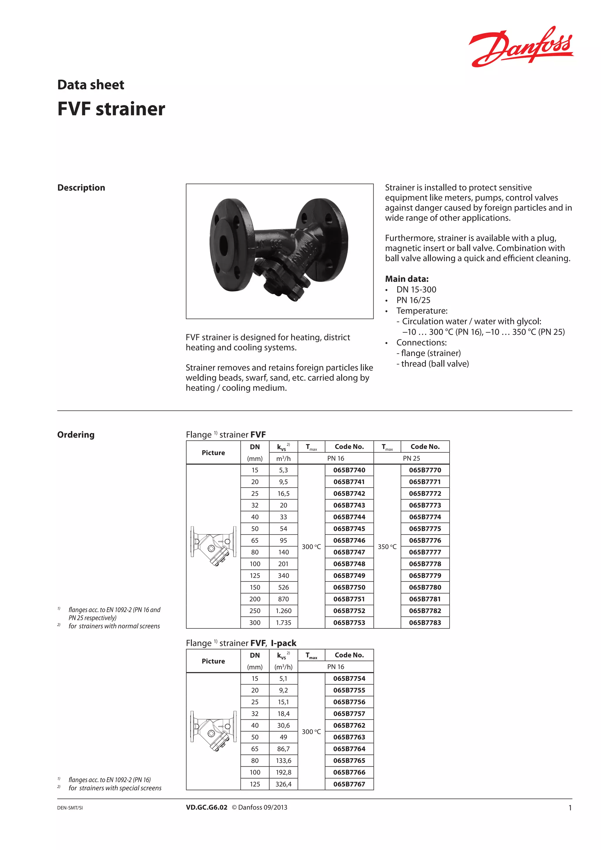
1VD.GC.G6.02 © Danfoss 09/2013DEN-SMT/SI
Data sheet
FVF strainer
FVF strainer is designed for heating, district
heating and cooling systems.
Strainer removes and retains foreign particles like
welding beads, swarf, sand, etc. carried along by
heating / cooling medium.
Description
Ordering Flange 1)
strainer FVF
Picture
DN kVS
2)
Tmax Code No. Tmax Code No.
(mm) m3
/h PN 16 PN 25
15 5,3
300 o
C
065B7740
350 o
C
065B7770
20 9,5 065B7741 065B7771
25 16,5 065B7742 065B7772
32 20 065B7743 065B7773
40 33 065B7744 065B7774
50 54 065B7745 065B7775
65 95 065B7746 065B7776
80 140 065B7747 065B7777
100 201 065B7748 065B7778
125 340 065B7749 065B7779
150 526 065B7750 065B7780
200 870 065B7751 065B7781
250 1.260 065B7752 065B7782
300 1.735 065B7753 065B7783
Flange 1)
strainer FVF, I-pack
Picture
DN kVS
2)
Tmax Code No.
(mm) (m3
/h) PN 16
15 5,1
300 o
C
065B7754
20 9,2 065B7755
25 15,1 065B7756
32 18,4 065B7757
40 30,6 065B7762
50 49 065B7763
65 86,7 065B7764
80 133,6 065B7765
100 192,8 065B7766
125 326,4 065B7767
1)
	 flanges acc. to EN 1092-2 (PN 16 and 		
	 PN 25 respectively)
2)
	 for strainers with normal screens
Strainer is installed to protect sensitive
equipment like meters, pumps, control valves
against danger caused by foreign particles and in
wide range of other applications.
Furthermore, strainer is available with a plug,
magnetic insert or ball valve. Combination with
ball valve allowing a quick and efficient cleaning.
Main data:
•	 DN 15-300
•	 PN 16/25
•	 Temperature:
-	Circulation water / water with glycol:
	 −10 … 300 °C (PN 16), −10 … 350 °C (PN 25)
•	 Connections:
	 - flange (strainer)
	 - thread (ball valve)
1)
	 flanges acc. to EN 1092-2 (PN 16)
2)
	 for strainers with special screens
2 VD.GC.G6.02 © Danfoss 09/2013 DEN-SMT/SI
Data sheet	 FVF strainer
Picture
DN PN FVF-Screen FVF-Screen
(mm) (bar) (normal) (fine)
15/20
16, 25
065B7810 065B7824
25 065B7812 065B7826
32 065B7813 065B7827
40 065B7814 065B7828
50 065B7815 065B7829
65 065B7816 065B7830
80 065B7817 065B7831
100 065B7818 065B7832
125 065B7819 065B7833
150 065B7820 065B7834
200 065B7821 065B7835
250 065B7822 065B7836
300 065B7823 065B7837
Accessories
Picture
DN FVF-M
Picture
DN FVF-B
(mm) magnetic insert (mm) ball valve
15
065B7790
10
(used for FVF
DN 15 - 50)
065B7802
20
25
065B7791
32
40 065B7792
50 065B7793
65 065B7794
15
(used for FVF
DN 65 - 300)
065B7801
80 065B7795
100
065B7796
125
150 065B7797
200 065B7798
250 065B7799
300 065B7800
Ordering (continuous) Spare parts
Technical data
Nominal diameter DN 15 20 25 32 40 50 65 80 100 125 150 200 250 300
kVS value
normal screen
m3
/h
5,3 9,5 16,5 20 33 54 95 140 201 340 526 870 1260 1735
fine screen 5,0 9,0 14,8 18 30 48 85 131 189 320 494 818 1184 1631
special screen 5,1 9,2 15,1 18,4 30,6 49 86,7 133,6 192,8 326,4 -
kVS value
(with magnetic insert)
normal screen 4,8 8,6 14,9 18 29 49 86 127 183 316 489 809 1172 1613
fine screen 4,5 8,1 13,3 16 27 44 77 119 170 297 459 760 1101 1516
Mesh size
normal screen
mm
0,54 0,87 1,18
fine screen 0,25
special screen 0,40 -
Number of meshses
normal screen
n/cm2
150 64 25
fine screen 625
special screen 280 -
Flow medium Circulation water / glycolic water up to 50%
Nominal pressure PN 16 or 25
Medium temperature o
C −10 ... 300 (PN16), −10 ... 350 (PN25)
Connection Flanges acc. to DIN EN 1092-2 (PN16 and PN25 respectively)
Materials
Body (strainer)
PN 16 Grey cast iron EN-GJL-250 (GG-25)
PN 25 Ductile iron EN-GJS-400-18-LT (GGG 40.3)
Body (ball valve) Dezincing free brass CuZn36Pb2As
Screen Stainless steel, mat. No 1.4301
Gasket Graphite
Picture
DN
FVF - Gasket
(mm)
15/20 065B7886
25/32 065B7887
40 065B7888
50 065B7889
65 065B7890
80 065B7891
100 065B7892
125 065B7893
150 065B7894
200 065B7895
250 065B7896
300 065B7897
3VD.GC.G6.02 © Danfoss 09/2013DEN-SMT/SI
o
C
PN
❶
❷
❷
❶
EN-GJS-400-18-LT
(GGG 40.3) PN25
EN-GJL-250
(GG 25) PN16
o
C
PN
0 	 120 	 140 	 160 	 180 	 200 	 220	 240 	 260 	 280 	 300 	 320 	 340 	350
10
15
20
25
AA
With magnetic insert With ball valve
Data sheet	 FVF strainer
Design
	 1.	Body
	 2.	Cover
	 3.	Screen	
	 4.	Gasket
	 5.	Screw
	 6.	Nut
	 7.	 Plug screw
	 8.	Magnet
	 9.	Washer
	10.	Handle
11. 	Ball
12.	 Stem
Pressure temperature
diagram
Ball valve diagram
Maximum allowed operating pressure as a function of medium temperature (according to EN 1092-2).
4 VD.GC.G6.02 Produced by Danfoss A/S © 09/2013
L
H
L1
D
DN
Data sheet	 FVF strainer
The medium flow direction must correspond to
an arrow on the strainer body.
Strainers are to be installed in horizontal position
with mesh bonet directed downwards.
Vertical position is also allowed (be aware -
when medium flows upwards strainer retains
all foreign particles but is not able to collect
them).
Sufficient space to pull out the mesh for
replacement and cleaning must be ensured.
Installation positions
Dimensions
DN L H
PN 16 PN 25
Weight
D d dk D d dk
mm (kg)
15 130 75 95 14 65 95 14 65 2,2
20 150 75 105 14 75 105 14 75 3,3
25 160 90 115 14 85 115 14 85 3,8
32 180 90 140 19 100 140 19 100 5,0
40 200 110 150 19 110 150 19 110 6,5
50 230 120 165 19 125 165 19 125 8,5
65 290 140 185 19 145 185 19 145 12,0
80 310 165 200 19 160 200 19 160 16,6
100 350 220 220 19 180 235 23 190 25,0
125 400 260 250 19 210 270 28 220 39,0
150 480 300 285 23 240 300 28 250 61,0
200 600 360 340 23 295 360 28 310 109
250 730 470 405 28 355 425 31 370 162
300 850 560 460 28 410 485 31 430 280
Ball valve
DN L L1 H D
mm
10 47 43 36 12,5
15 60 50 52 15,5

Strainers fvf

  • 1.
    1VD.GC.G6.02 © Danfoss09/2013DEN-SMT/SI Data sheet FVF strainer FVF strainer is designed for heating, district heating and cooling systems. Strainer removes and retains foreign particles like welding beads, swarf, sand, etc. carried along by heating / cooling medium. Description Ordering Flange 1) strainer FVF Picture DN kVS 2) Tmax Code No. Tmax Code No. (mm) m3 /h PN 16 PN 25 15 5,3 300 o C 065B7740 350 o C 065B7770 20 9,5 065B7741 065B7771 25 16,5 065B7742 065B7772 32 20 065B7743 065B7773 40 33 065B7744 065B7774 50 54 065B7745 065B7775 65 95 065B7746 065B7776 80 140 065B7747 065B7777 100 201 065B7748 065B7778 125 340 065B7749 065B7779 150 526 065B7750 065B7780 200 870 065B7751 065B7781 250 1.260 065B7752 065B7782 300 1.735 065B7753 065B7783 Flange 1) strainer FVF, I-pack Picture DN kVS 2) Tmax Code No. (mm) (m3 /h) PN 16 15 5,1 300 o C 065B7754 20 9,2 065B7755 25 15,1 065B7756 32 18,4 065B7757 40 30,6 065B7762 50 49 065B7763 65 86,7 065B7764 80 133,6 065B7765 100 192,8 065B7766 125 326,4 065B7767 1) flanges acc. to EN 1092-2 (PN 16 and PN 25 respectively) 2) for strainers with normal screens Strainer is installed to protect sensitive equipment like meters, pumps, control valves against danger caused by foreign particles and in wide range of other applications. Furthermore, strainer is available with a plug, magnetic insert or ball valve. Combination with ball valve allowing a quick and efficient cleaning. Main data: • DN 15-300 • PN 16/25 • Temperature: - Circulation water / water with glycol: −10 … 300 °C (PN 16), −10 … 350 °C (PN 25) • Connections: - flange (strainer) - thread (ball valve) 1) flanges acc. to EN 1092-2 (PN 16) 2) for strainers with special screens
  • 2.
    2 VD.GC.G6.02 ©Danfoss 09/2013 DEN-SMT/SI Data sheet FVF strainer Picture DN PN FVF-Screen FVF-Screen (mm) (bar) (normal) (fine) 15/20 16, 25 065B7810 065B7824 25 065B7812 065B7826 32 065B7813 065B7827 40 065B7814 065B7828 50 065B7815 065B7829 65 065B7816 065B7830 80 065B7817 065B7831 100 065B7818 065B7832 125 065B7819 065B7833 150 065B7820 065B7834 200 065B7821 065B7835 250 065B7822 065B7836 300 065B7823 065B7837 Accessories Picture DN FVF-M Picture DN FVF-B (mm) magnetic insert (mm) ball valve 15 065B7790 10 (used for FVF DN 15 - 50) 065B7802 20 25 065B7791 32 40 065B7792 50 065B7793 65 065B7794 15 (used for FVF DN 65 - 300) 065B7801 80 065B7795 100 065B7796 125 150 065B7797 200 065B7798 250 065B7799 300 065B7800 Ordering (continuous) Spare parts Technical data Nominal diameter DN 15 20 25 32 40 50 65 80 100 125 150 200 250 300 kVS value normal screen m3 /h 5,3 9,5 16,5 20 33 54 95 140 201 340 526 870 1260 1735 fine screen 5,0 9,0 14,8 18 30 48 85 131 189 320 494 818 1184 1631 special screen 5,1 9,2 15,1 18,4 30,6 49 86,7 133,6 192,8 326,4 - kVS value (with magnetic insert) normal screen 4,8 8,6 14,9 18 29 49 86 127 183 316 489 809 1172 1613 fine screen 4,5 8,1 13,3 16 27 44 77 119 170 297 459 760 1101 1516 Mesh size normal screen mm 0,54 0,87 1,18 fine screen 0,25 special screen 0,40 - Number of meshses normal screen n/cm2 150 64 25 fine screen 625 special screen 280 - Flow medium Circulation water / glycolic water up to 50% Nominal pressure PN 16 or 25 Medium temperature o C −10 ... 300 (PN16), −10 ... 350 (PN25) Connection Flanges acc. to DIN EN 1092-2 (PN16 and PN25 respectively) Materials Body (strainer) PN 16 Grey cast iron EN-GJL-250 (GG-25) PN 25 Ductile iron EN-GJS-400-18-LT (GGG 40.3) Body (ball valve) Dezincing free brass CuZn36Pb2As Screen Stainless steel, mat. No 1.4301 Gasket Graphite Picture DN FVF - Gasket (mm) 15/20 065B7886 25/32 065B7887 40 065B7888 50 065B7889 65 065B7890 80 065B7891 100 065B7892 125 065B7893 150 065B7894 200 065B7895 250 065B7896 300 065B7897
  • 3.
    3VD.GC.G6.02 © Danfoss09/2013DEN-SMT/SI o C PN ❶ ❷ ❷ ❶ EN-GJS-400-18-LT (GGG 40.3) PN25 EN-GJL-250 (GG 25) PN16 o C PN 0 120 140 160 180 200 220 240 260 280 300 320 340 350 10 15 20 25 AA With magnetic insert With ball valve Data sheet FVF strainer Design 1. Body 2. Cover 3. Screen 4. Gasket 5. Screw 6. Nut 7. Plug screw 8. Magnet 9. Washer 10. Handle 11. Ball 12. Stem Pressure temperature diagram Ball valve diagram Maximum allowed operating pressure as a function of medium temperature (according to EN 1092-2).
  • 4.
    4 VD.GC.G6.02 Producedby Danfoss A/S © 09/2013 L H L1 D DN Data sheet FVF strainer The medium flow direction must correspond to an arrow on the strainer body. Strainers are to be installed in horizontal position with mesh bonet directed downwards. Vertical position is also allowed (be aware - when medium flows upwards strainer retains all foreign particles but is not able to collect them). Sufficient space to pull out the mesh for replacement and cleaning must be ensured. Installation positions Dimensions DN L H PN 16 PN 25 Weight D d dk D d dk mm (kg) 15 130 75 95 14 65 95 14 65 2,2 20 150 75 105 14 75 105 14 75 3,3 25 160 90 115 14 85 115 14 85 3,8 32 180 90 140 19 100 140 19 100 5,0 40 200 110 150 19 110 150 19 110 6,5 50 230 120 165 19 125 165 19 125 8,5 65 290 140 185 19 145 185 19 145 12,0 80 310 165 200 19 160 200 19 160 16,6 100 350 220 220 19 180 235 23 190 25,0 125 400 260 250 19 210 270 28 220 39,0 150 480 300 285 23 240 300 28 250 61,0 200 600 360 340 23 295 360 28 310 109 250 730 470 405 28 355 425 31 370 162 300 850 560 460 28 410 485 31 430 280 Ball valve DN L L1 H D mm 10 47 43 36 12,5 15 60 50 52 15,5