This document provides an overview of the Ackermann Clino Systems product catalog for 2013. It includes:
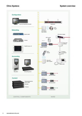
1) An overview of the Clino Systevo call system, which provides optoacoustic and digital communication features across multiple levels from rooms to zones.
2) Descriptions of the central components of the system including the Systevo Control panel, audio interface, and workstation.
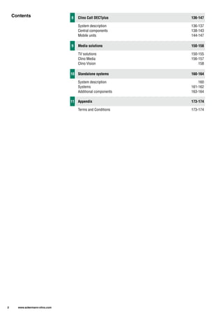
3) Lists of the sections contained in the catalog covering central components, room components, corridor components, and installation accessories.