NPTEL fundamentals of manufacturing process part 1
1.
Fundamentals of ManufacturingProcesses
Metal working processes: Forging
DHEERENDRA KUMAR DWIVEDI
MECHANICAL & INDUSTRIAL ENGINEERING DEPARTMENT
1
2.
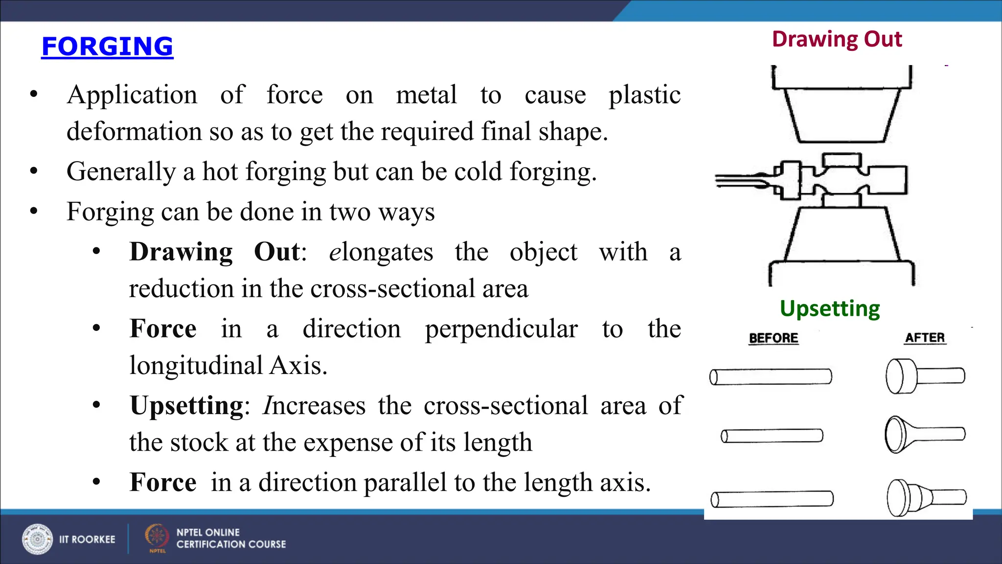
FORGING
• Application offorce on metal to cause plastic
deformation so as to get the required final shape.
• Generally a hot forging but can be cold forging.
• Forging can be done in two ways
• Drawing Out: elongates the object with a
reduction in the cross-sectional area
• Force in a direction perpendicular to the
longitudinal Axis.
• Upsetting: Increases the cross-sectional area of
the stock at the expense of its length
• Force in a direction parallel to the length axis.
Drawing Out
Upsetting
3.
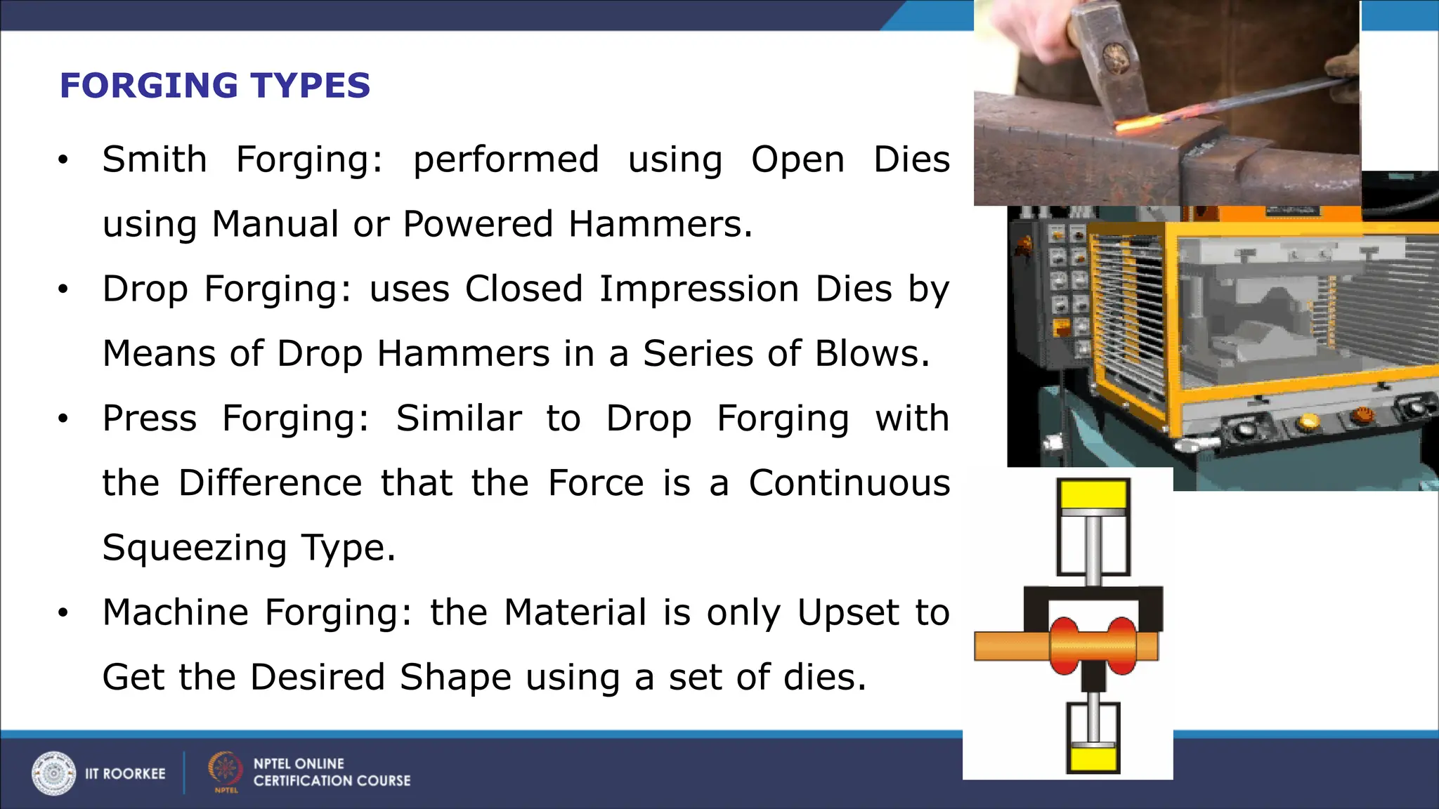
FORGING TYPES
• SmithForging: performed using Open Dies
using Manual or Powered Hammers.
• Drop Forging: uses Closed Impression Dies by
Means of Drop Hammers in a Series of Blows.
• Press Forging: Similar to Drop Forging with
the Difference that the Force is a Continuous
Squeezing Type.
• Machine Forging: the Material is only Upset to
Get the Desired Shape using a set of dies.
5.
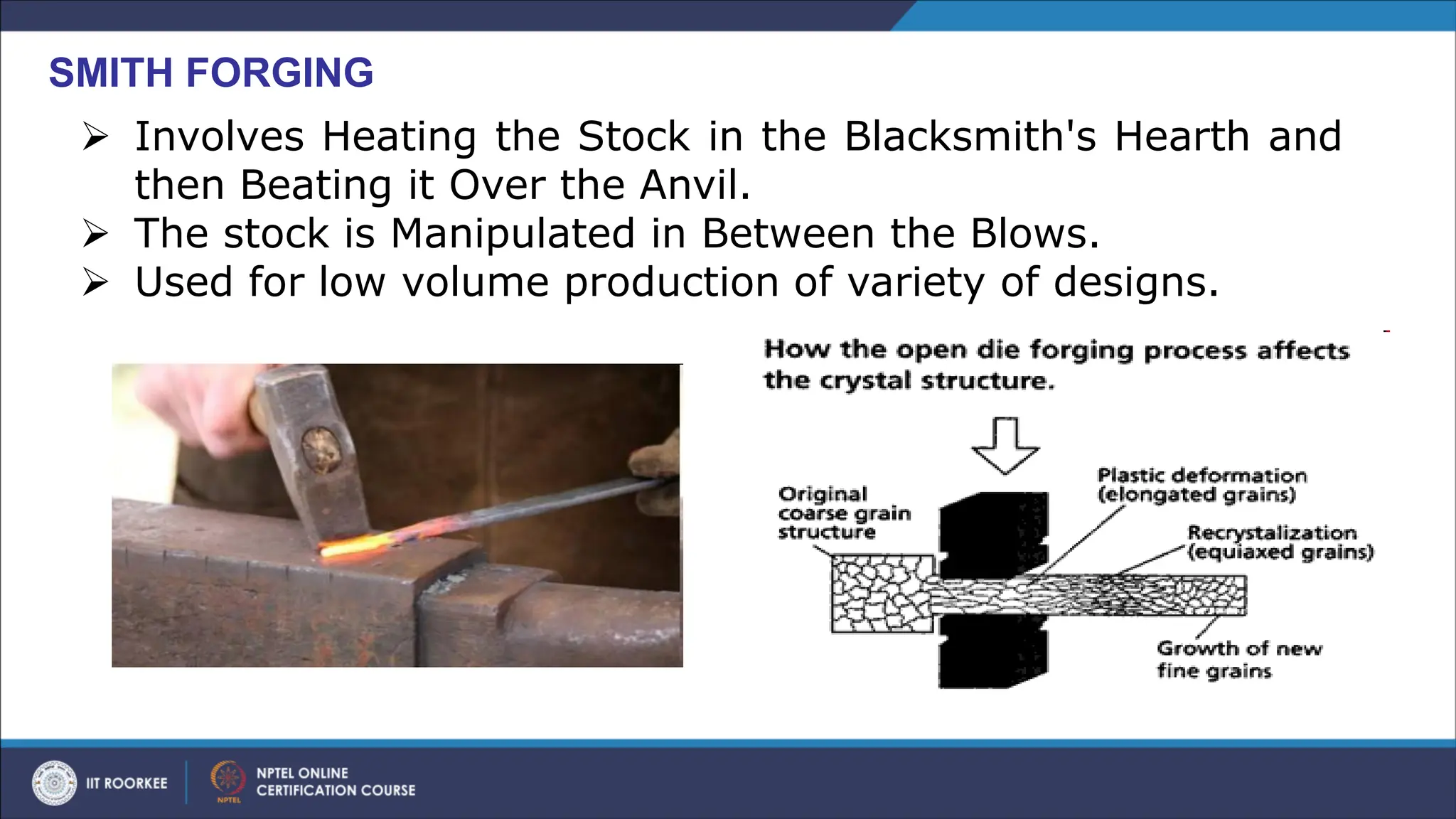
SMITH FORGING
➢ InvolvesHeating the Stock in the Blacksmith's Hearth and
then Beating it Over the Anvil.
➢ The stock is Manipulated in Between the Blows.
➢ Used for low volume production of variety of designs.
6.
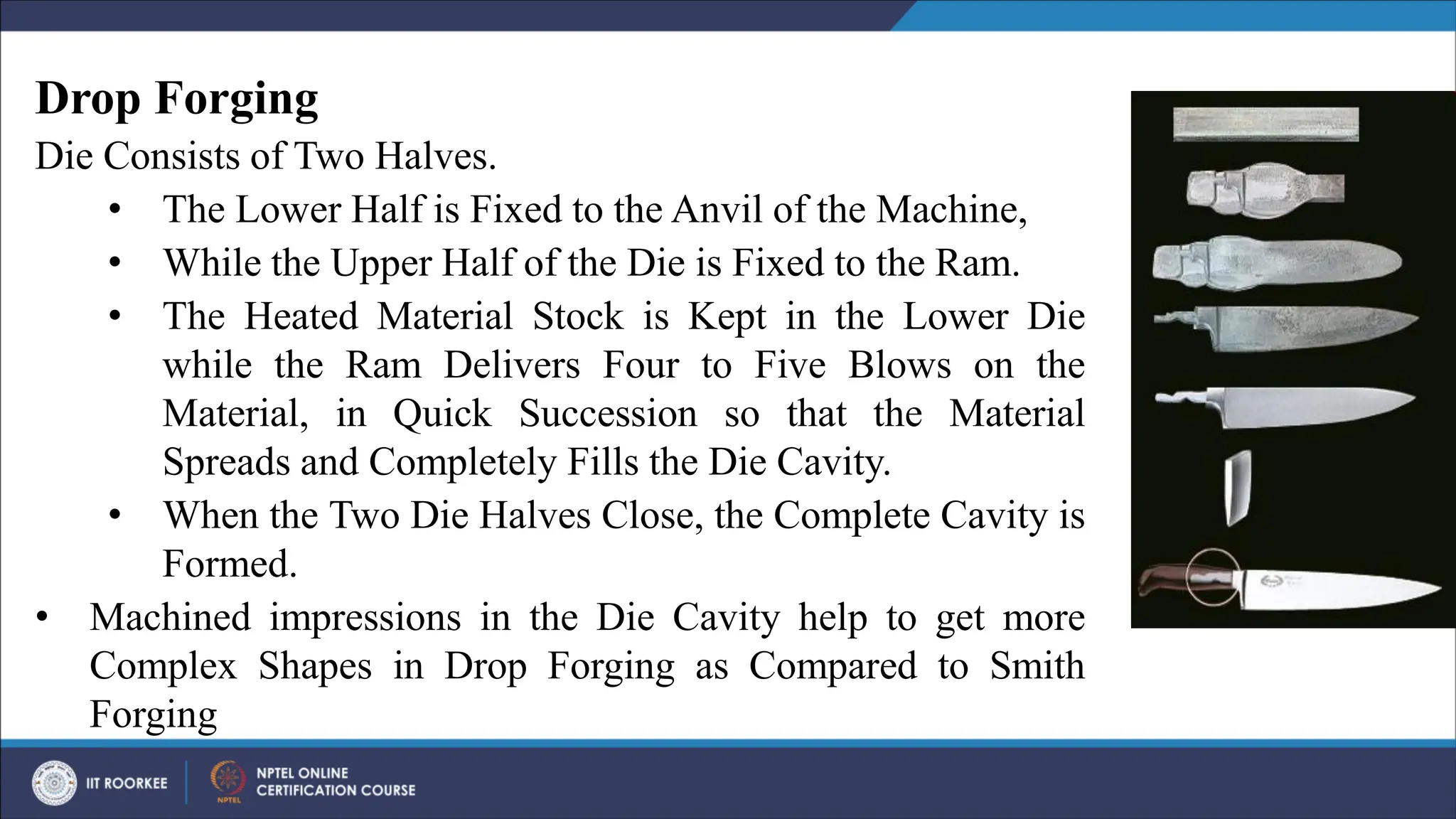
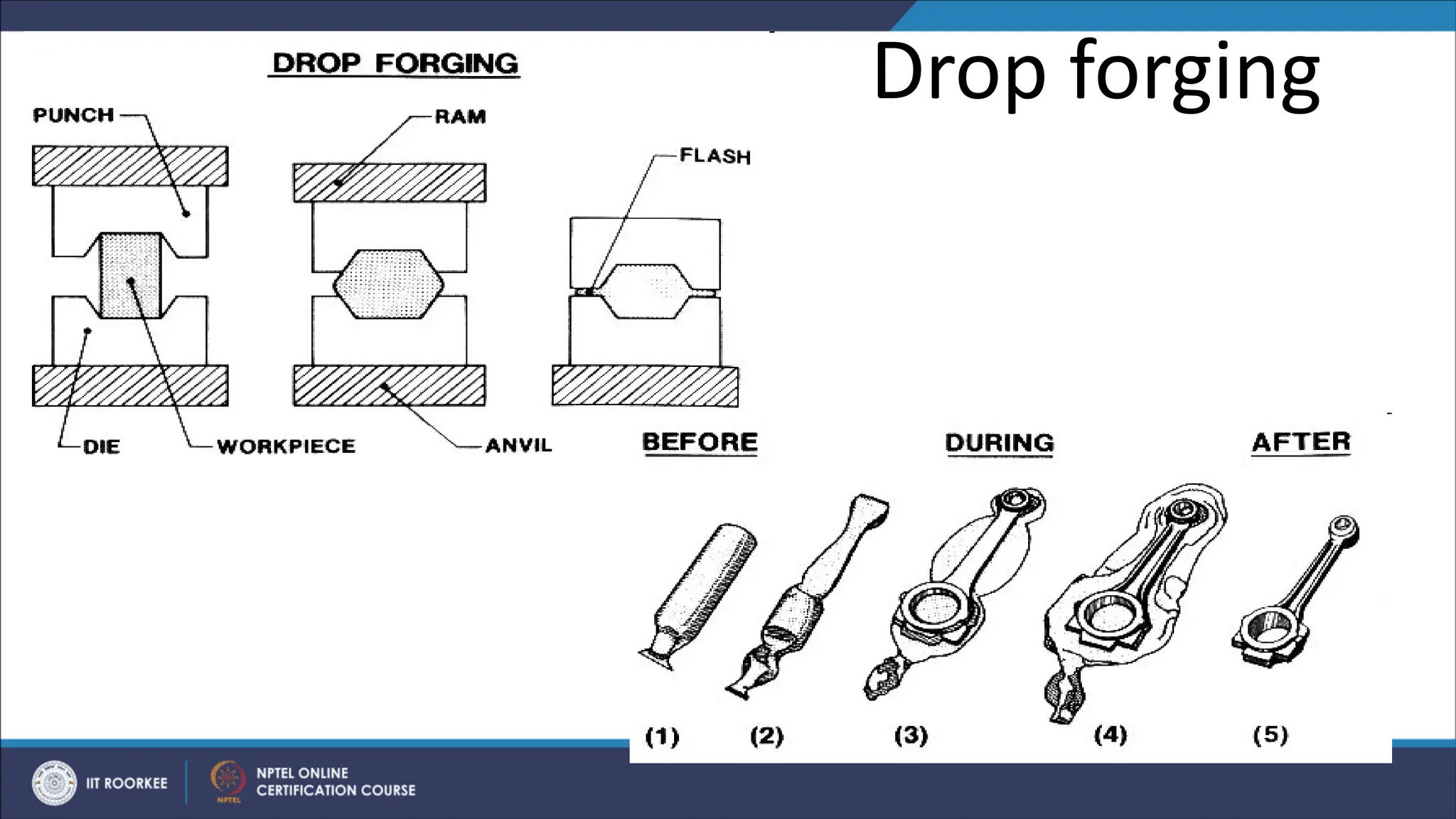
Drop Forging
Die Consistsof Two Halves.
• The Lower Half is Fixed to the Anvil of the Machine,
• While the Upper Half of the Die is Fixed to the Ram.
• The Heated Material Stock is Kept in the Lower Die
while the Ram Delivers Four to Five Blows on the
Material, in Quick Succession so that the Material
Spreads and Completely Fills the Die Cavity.
• When the Two Die Halves Close, the Complete Cavity is
Formed.
• Machined impressions in the Die Cavity help to get more
Complex Shapes in Drop Forging as Compared to Smith
Forging
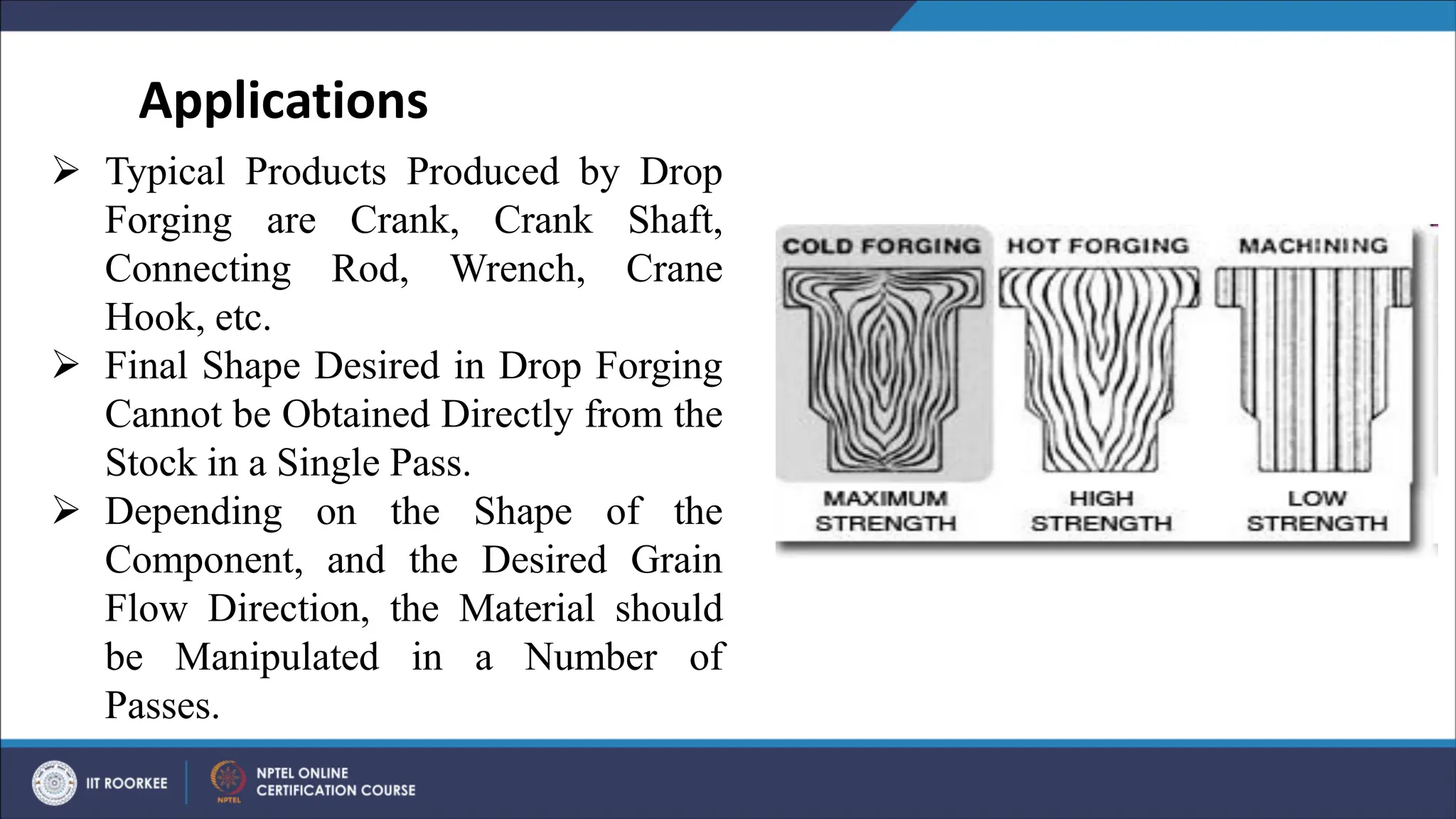
➢ Typical ProductsProduced by Drop
Forging are Crank, Crank Shaft,
Connecting Rod, Wrench, Crane
Hook, etc.
➢ Final Shape Desired in Drop Forging
Cannot be Obtained Directly from the
Stock in a Single Pass.
➢ Depending on the Shape of the
Component, and the Desired Grain
Flow Direction, the Material should
be Manipulated in a Number of
Passes.
Applications
9.
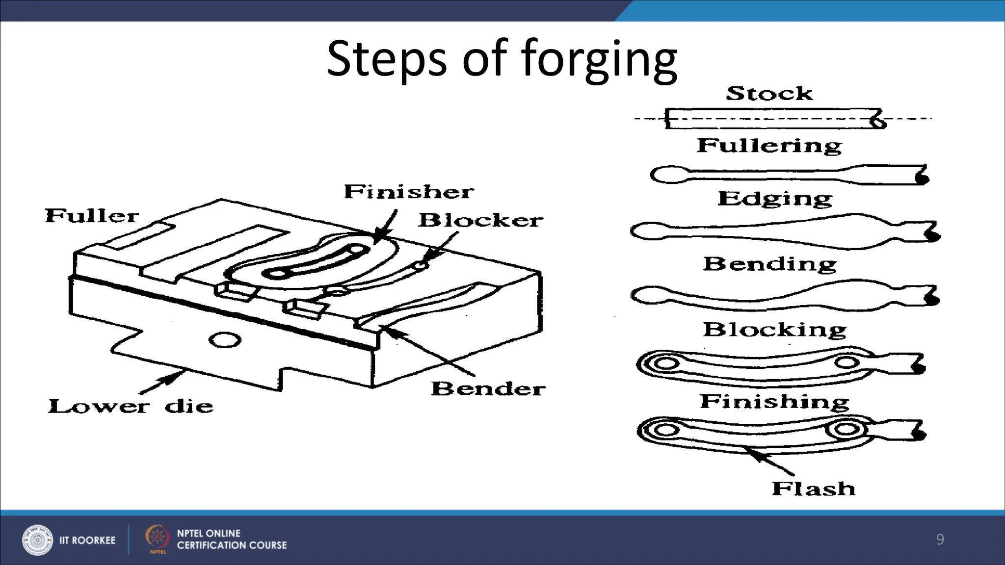
Steps of forging
9
•Fullering impression: reducing stock to the desired size.
• Edging impression (preforming): ensures defect-free flow of
material, complete die fill and minimum flash loss.
• Bending impression: for the parts having a bent shape.
• Blocking is a step before finishing. the material flows to deep
pockets, sharp corners, etc. before the finishing impression
without flash.
• Finishing: is the final impression for actual shape .at this stage a
little extra material is added to the stock forms the flash and
surrounds the forging in the parting plane.
• Trimming is removal of the extra flash present around the forging
to make the forging in usable .
10.
• In PressForging: Uniform Deformation Throughout the Depth.
• Cleaner impressed as compared to the Jarred Impressions produced in
the drop forged components.
• Press forging suits for smaller size components than drop forging
• As former needs higher Press Capacity for Deforming in Closed
Impression Dies.
• Press capacities may range from 5 MN to 50 MN for normal
applications and as high as 600 MN for special heavy duty
applications.
Press Forging vs Drop Forging
11.
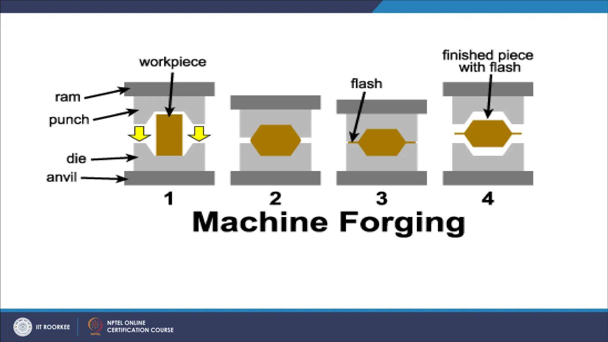
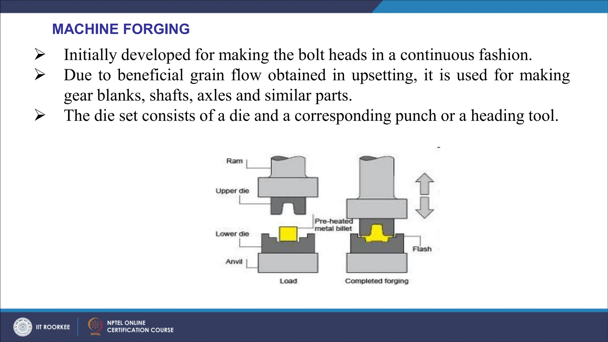
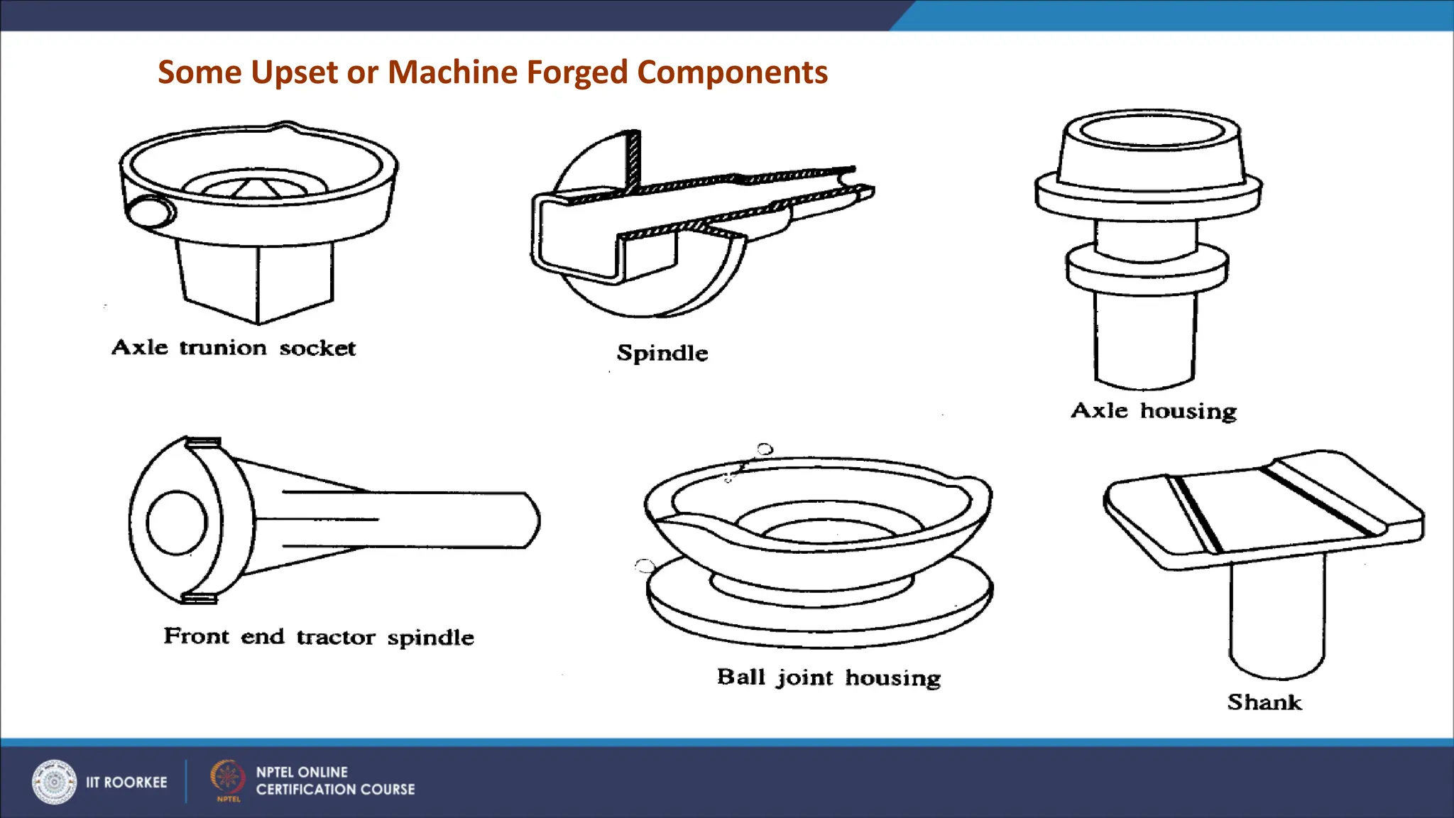
➢ Initially developedfor making the bolt heads in a continuous fashion.
➢ Due to beneficial grain flow obtained in upsetting, it is used for making
gear blanks, shafts, axles and similar parts.
➢ The die set consists of a die and a corresponding punch or a heading tool.
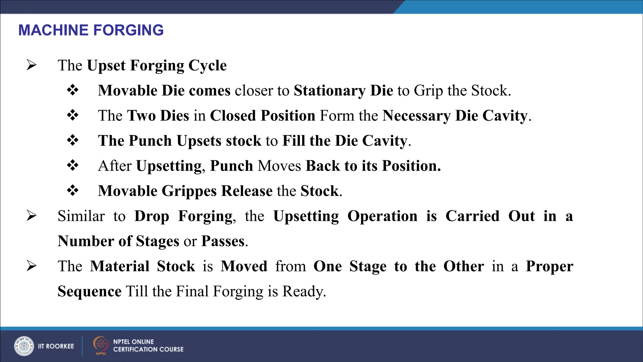
MACHINE FORGING
12.
➢ The UpsetForging Cycle
❖ Movable Die comes closer to Stationary Die to Grip the Stock.
❖ The Two Dies in Closed Position Form the Necessary Die Cavity.
❖ The Punch Upsets stock to Fill the Die Cavity.
❖ After Upsetting, Punch Moves Back to its Position.
❖ Movable Grippes Release the Stock.
➢ Similar to Drop Forging, the Upsetting Operation is Carried Out in a
Number of Stages or Passes.
➢ The Material Stock is Moved from One Stage to the Other in a Proper
Sequence Till the Final Forging is Ready.
MACHINE FORGING
FORGING DEFECTS
➢ UnfilledSections: of Die Cavity by the Flowing Material due to:
❖ Improper Design of Forging Die or
❖ Faulty Forging Techniques.
➢ Cold Shut: A Small Crack at the Corners of the Forging due to Improper Design of
the Die e.g. Corner and Fillet Radii are Small which in turn results in small cracks due
to poor flow of materials at the Corner.
➢ Scale Pits: Irregular Depressions on the Surface of the Forging primarily due to
improper Cleaning of the Stock Used for Forging.
➢ The Oxide and Scale Present on the Stock Surface Gets Embedded into the Finished
Forging Surface. When the Forging is Cleaned by Pickling, these are Seen as
Depressions on the Forging Surface.
15.
➢ Die Shift:
CAUSES:Die Shift is Caused by the
❖ Misalignment of the Two Die Halves Making the Two Halves of the Forging to be
of Improper Shape.