The wordmembrane originates from the Latin word
membrana which means a skin.
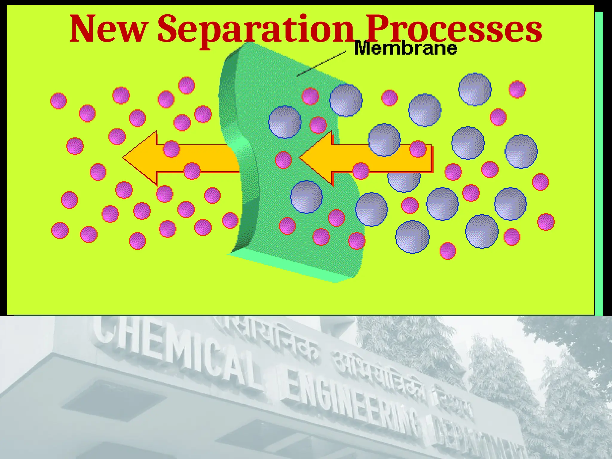
A membrane is a selective barrier that permits the
separation of certain species in a fluid by combination of
sieving and sorption diffusion mechanism.
Separation is achieved by selectively passing
(permeating) one or more components of a stream
through the membrane while retarding the passage of
one or more other components.
Membranes can selectively separate components over a
wide range of particle sizes and molecular weights, from
macromolecular materials such as starch and protein to
monovalent ions.
Membranes have gained an important place in chemical technology and
are used in a broad range of applications.
3.
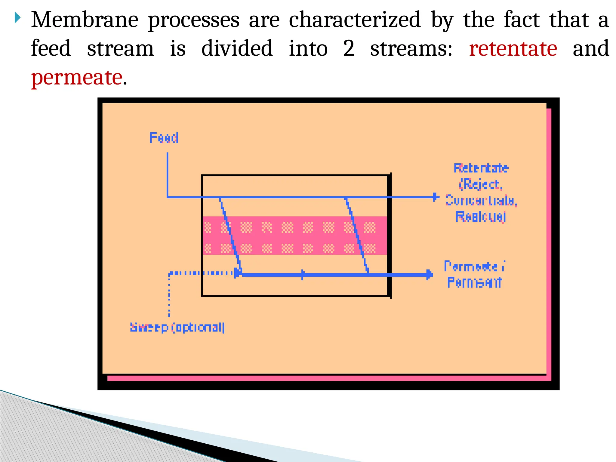
Membrane processesare characterized by the fact that a
feed stream is divided into 2 streams: retentate and
permeate.
4.
The retentateis that part of the feed that does not pass
through the membrane, while the permeate is that part
of the feed that does pass through the membrane.
The optional "sweep" is a gas or liquid that is used to help
remove the permeate.
The component(s) of interest in membrane separation is
known as the solute. The solute can be retained on the
membrane and removed in the retentate or passed through
the membrane in the permeate.
5.
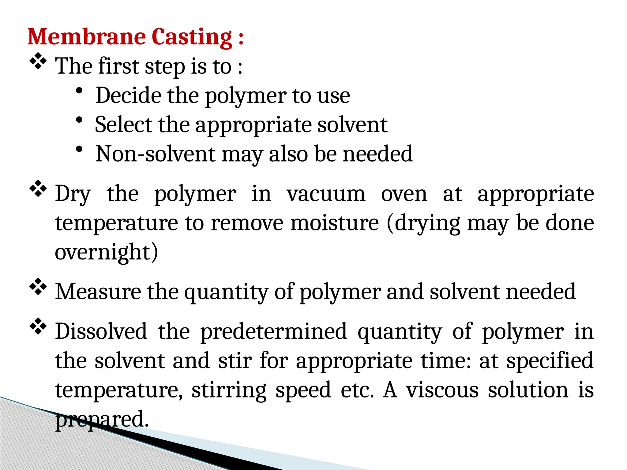
Membrane Casting :
The first step is to :
• Decide the polymer to use
• Select the appropriate solvent
• Non-solvent may also be needed
Dry the polymer in vacuum oven at appropriate
temperature to remove moisture (drying may be done
overnight)
Measure the quantity of polymer and solvent needed
Dissolved the predetermined quantity of polymer in
the solvent and stir for appropriate time: at specified
temperature, stirring speed etc. A viscous solution is
prepared.
6.
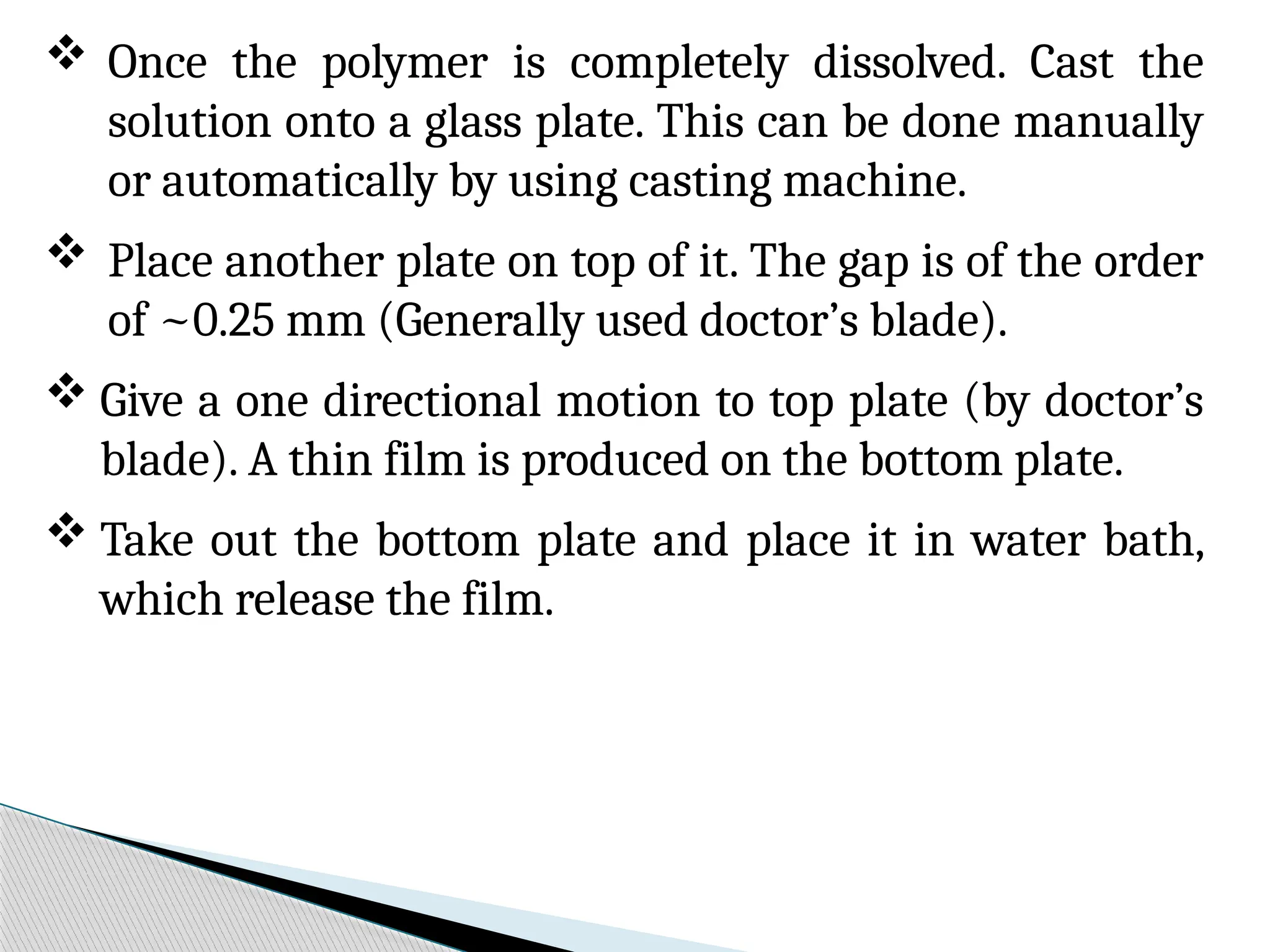
Once thepolymer is completely dissolved. Cast the
solution onto a glass plate. This can be done manually
or automatically by using casting machine.
Place another plate on top of it. The gap is of the order
of ~0.25 mm (Generally used doctor’s blade).
Give a one directional motion to top plate (by doctor’s
blade). A thin film is produced on the bottom plate.
Take out the bottom plate and place it in water bath,
which release the film.
7.
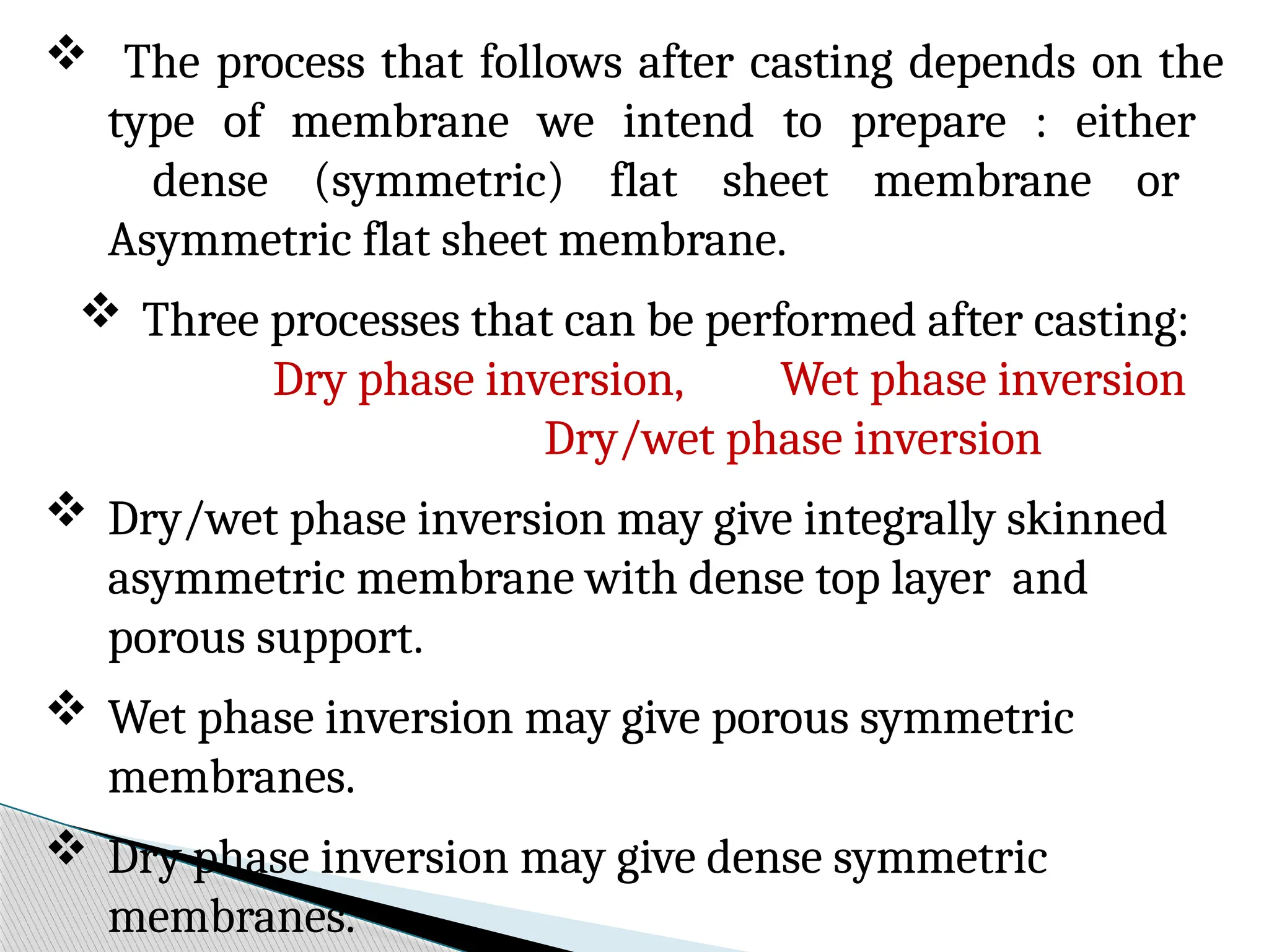
The processthat follows after casting depends on the
type of membrane we intend to prepare : either
dense (symmetric) flat sheet membrane or
Asymmetric flat sheet membrane.
Three processes that can be performed after casting:
Dry phase inversion, Wet phase inversion
Dry/wet phase inversion
Dry/wet phase inversion may give integrally skinned
asymmetric membrane with dense top layer and
porous support.
Wet phase inversion may give porous symmetric
membranes.
Dry phase inversion may give dense symmetric
membranes.
8.
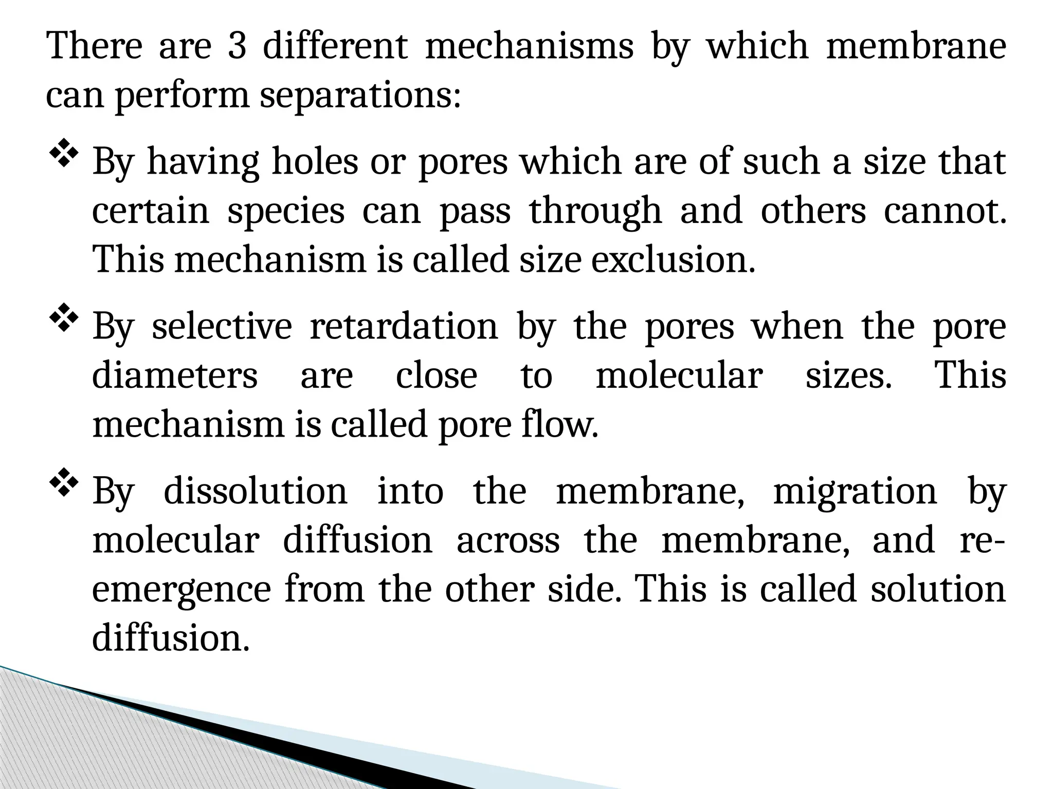
There are 3different mechanisms by which membrane
can perform separations:
By having holes or pores which are of such a size that
certain species can pass through and others cannot.
This mechanism is called size exclusion.
By selective retardation by the pores when the pore
diameters are close to molecular sizes. This
mechanism is called pore flow.
By dissolution into the membrane, migration by
molecular diffusion across the membrane, and re-
emergence from the other side. This is called solution
diffusion.
9.
Membrane selection dependson a variety of factors :
Composition of the feed solution
Operating parameters
Application type
Separation goals
Chain interactions, chain rigidity, functional group
polarity, and stereoisomerism also need to be factored
into polymer choice and organic membrane
manufacturing
Organic and inorganic membranes have their own
advantages and disadvantages, it is important to
determine what type of membrane or polymer is most
suitable for the application.
10.
A majority ofindustrial membranes consist of
synthetic or natural polymers; membranes with
both types of polymers are known as organic
membranes.
Examples of synthetic polymers include
Polytetrafluoroethylene (Teflon PTFE),
Polyamide-imide (PAI), and
Polyvinylidenedifluoride (PVDF)
Polystyrene and polytetrafluoroethylene (Teflon/
PTFE).
Natural polymers include rubber, wool, and
cellulose.
11.
Membranes canalso be made from other non-
polymeric materials. Such membranes include
inorganic membranes (for example metal, ceramic,
carbon and zeolites) and liquid membranes.
In addition, recent developments had led to the
introduction of the so-called Hybrid Membranes (or
Mixed Matrix Membranes), where both organic and
inorganic components are used.
Another variation in membranes application is the
Bipolar Membranes (BPM). where membranes of
different ionic charge are "sandwiched" together.
12.
Artificial / Syntheticpolymers are synthesized by the
polymerization of a monomer or co-polymerization of 2
monomers. The resulting polymer (Polymerization) is
categorized as having:
A long, linear chain such as polyethylene
A, branched chain, such as polysulfone or polybutadiene
A, three dimensional highly cross-linked structure, such
as phenol-formaldehyde.
moderately cross-linked structure, such as butyl rubber
13.
Linear-chained polymers aremore soluble in organic
solvents. They become pliable or moldable with
temperature increase and are known as thermoplastic
polymers.
On the other hand, cross-linked polymers are almost
insoluble in organic solvents. They do not soften with
temperature increase and are known as thermosetting
polymers.
14.
Polymer selectionmust be based on
compatibility with membrane fabrication
technology and intended application use.
For example, the polymer may require a low
affinity toward the permeate, while other
times it may need to withstand harsh cleaning
conditions due to membrane fouling.
Chain interactions, chain rigidity, functional
group polarity, and stereoisomerism also need
to be factored into polymer choice and organic
membrane manufacturing.
15.
Inorganic Membranes
Inorganic membranesrefer to membranes made of
materials such as ceramic, carbon, silica, zeolite,
various oxides (alumina, titania, zirconia)
and metals such as palladium, silver and their alloys.
Inorganic membranes can be classified into 2 major
categories based on its structure:
Porous inorganic membranes and
Dense (non-porous) inorganic membranes.
Microporous inorganic membranes have 2
different structures:
Symmetric and asymmetric; and include both
amorphous and crystalline membranes.
16.
Application ofdense inorganic membranes is
primarily for highly selective separation of gases
such as hydrogen and oxygen.
However, dense membranes have limited
industrial application due to their low
permeability compared to porous inorganic
membranes.
Therefore, today's commercial inorganic
membrane market is dominated by porous
membranes.
17.
Advantages that inorganicmembrane
possesses are
High thermal and chemical stability,
Inertness to microbiological degradation, and
Ease of cleaning after fouling compared to
organic counterparts.
However, inorganic membranes
Tend to have higher capital costs due to specific
thickness requirements needed to withstand
pressure drop differences.
18.
Metallic membranesare made from sintering metal
powders such as tungsten, palladium or stainless steel and
then depositing them onto a porous substrate.
The main use of metallic membranes is for hydrogen
separation with palladium (Pd) and its alloy being the
primary choice of material, due to its high solubility and
permeability for hydrogen. Palladium, however, is
expensive.
Alternative to palladium and less expensive are tantalum
and vanadium, which are also quite permeable to
hydrogen.
Recent focus is on supported thin metallic membranes
with thickness ranging from submicron to a few ten
microns. The advantages include
Reduced material costs,
19.
Another applicationis the use of these
membranes to control the feed rate during partial
oxidation reactions (e.g. addition of hydrogen).
A major problem associated with metal
membranes is the surface poisoning effects (e.g.
by a carbon-containing source) which can be
more significant for thin metal membranes.
20.
Ceramic membranesconsist of metal (Al or Ti)
and non-metal (oxides, nitride, or carbide).
They are generally used for highly acidic or basic
environments due to inertness.
They have the advantages of being chemically inert
and stable at high temperatures.
This stability makes ceramic microfiltration and
ultrafiltration membranes particularly suitable for
food, biotechnology and pharmaceutical
applications in which membranes require repeated
steam sterilization and chemical cleaning.
21.
Ceramic membraneshave also been proposed for gas
separations.
An example application of recent development is in
the production and processing of syngas (synthetic
gas - a mixture of hydrogen and carbon monoxide).
The key part of the process involves the separation of
oxygen from air in the form of ions to oxidize the
methane.
The downside of ceramic membranes is the high
sensitivity to temperature gradient, which leads to
membrane cracking.
22.
Zeolite membranes
Zeolitesare microporous crystalline alumina-
silicate with a uniform pore size.
Zeolites are used as catalysts or adsorbents in a
form of micron or submicron-sized crystallites
embedded in millimeter-sized granules.
Zeolite membranes are used in highly-selective
gas separation due to highly uniform pore size.
This material also has a catalytic characteristic,
which is beneficial for catalytic membrane reactor
applications.
23.
Few downsidesof zeolite membranes include
Relatively low gas flux and
Thicker layer requirements to prevent cracks
and pinholes.
Overcome: use thin layer supported on others.
Other problem: Thermal effect of zeolites. The
zeolite layer can exhibit negative thermal
expansion, i.e. in the high temperature region the
zeolite layer shrinks …. But the support
continuously expands, resulting in thermal stress
problems for the attachment of the zeolite layer to
the support, as well as for the connection of the
individual micro-crystals within the zeolite layer.
24.
Types of motionof molecules through barrier
1) Permeation:
a) Dissolution of permeating molecules in the
membrane
b) Diffusion of dissolved molecules
c) Desorption of penetrant molecules to the
downstream side.
2) Knudsen diffusion (d/ < 0.2):
λ
Single gaseous molecules diffuse under
rarefied conditions so that the mean free path
is longer than the pore diameter.
3) Convection (d/ > 20):
λ
Viscous flow through the pores of
ultrafiltration and microfiltration.
25.
Permeation mechanism
Herewe are talking about almost non porous
membrane or pores are very small in case of reverse
osmosis and nano filtration.
The solute are getting dissolved in the dissolution steps,
solute have getting dissolved in the membrane phase,
and because of the concentration gradient, it will
diffuse from upstream to permeate side (feed to the
permeate side) through the membrane matrix then
again, because of the concentration gradient in the
permeate side the concentration is this nothing almost
and it get dissolved in the permeate side these three
steps including a in total they are called permeation
mechanism.
26.
• Second oneis, Knudsen diffusion
(d/<0.2)- d is the core diameter and is
the mean free path of the molecule. These are
basically transport of gaseous species under
rarefied condition.
• Third one is convection (d/ > 20) - if (d/
> 20) then pure convection will be taking place
under the pressure gradient.
27.
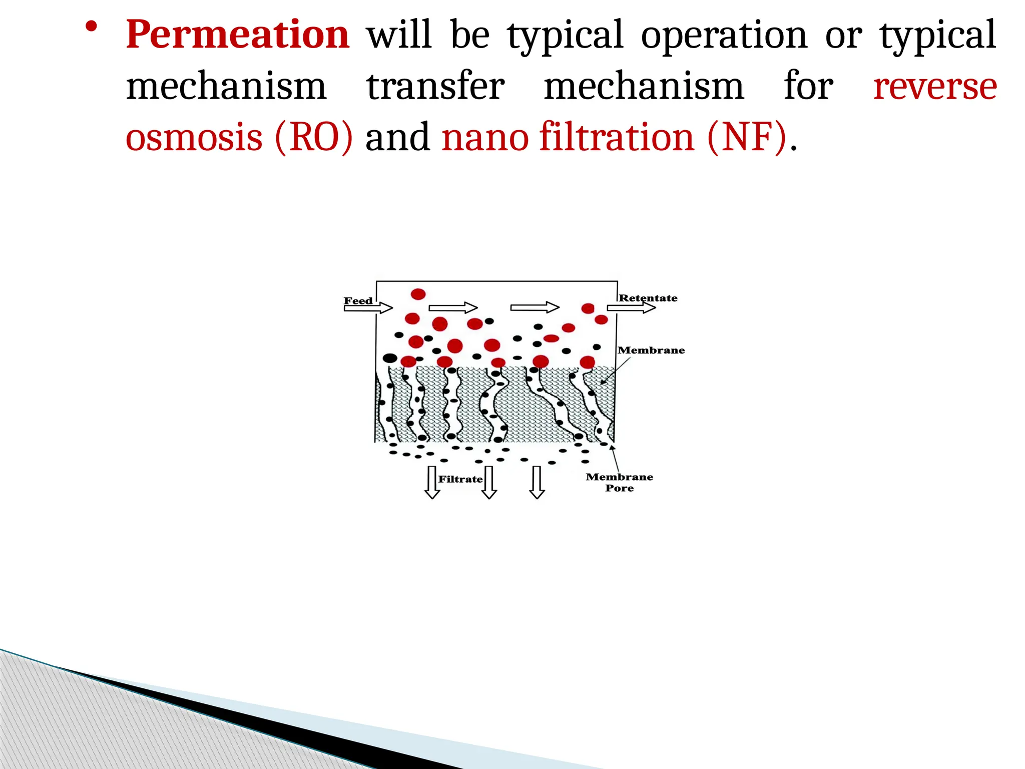
• Permeation willbe typical operation or typical
mechanism transfer mechanism for reverse
osmosis (RO) and nano filtration (NF).
• Both diffusion and convection will be more or less
predominant as we go towards the more pore size
of the membrane /next relax pore size of the
membrane.
• The mechanism is transfer from diffusion to the
convection right for lower molecular, cut off ultra
filtration membrane.
• For micro filtration membrane, convection is
the only mechanism.
28.
Transport mechanisms andperformance
parameters (Book
Chapter)
Sieving or size exclusion is the governing mechanism for
MF or higher pore size UF membranes.
Permeation, i.e., solute dissolution in membrane phase
from feed, diffusion through the membrane and
desorption in permeate is the governing mechanism of
denser membranes, like, RO and NF.
Performance parameters of any membrane based
process are mainly permeability and retention.
Permeability indicates how porous the membrane is and
it is directly related to the throughput of the process.
29.
Retention ofmembranes is an indicative of its
selectivity. In fact, membranes with high
permeability have lower selectivity.
Therefore, there should be a judicious trade-off
between permeability and retention of the
membrane for a particular application.
Hydrophilicity of membrane surface sometimes
becomes important as it imparts the anti-
fouling property to the surface, thereby
lowering the membrane fouling and
subsequently enhancing its life.
30.
Generally, membraneshave a pore size
distribution and hence average pore size of
membrane is denoted by the molecular weight
of solute that is retained 90% by the
membrane and this molecular weight is known
as molecular weight cut off (MWCO).
A membrane having a rating of 10000 MWCO
means it retains solutes of molecular weight
above 10000 Da and allows permeation of
solutes having molecular weight less than that.
31.
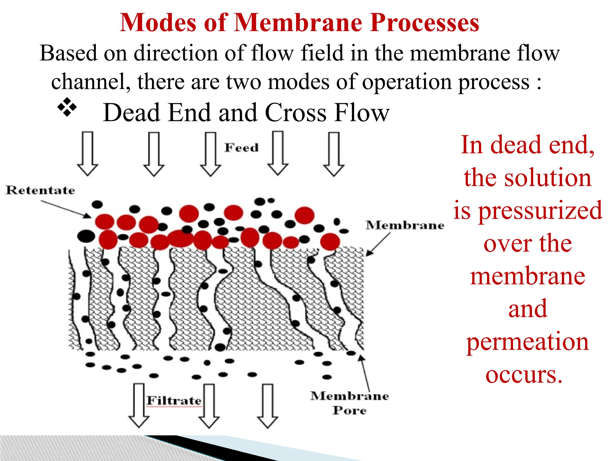
Modes of MembraneProcesses
Based on direction of flow field in the membrane flow
channel, there are two modes of operation process :
Dead End and Cross Flow
In dead end,
the solution
is pressurized
over the
membrane
and
permeation
occurs.
32.
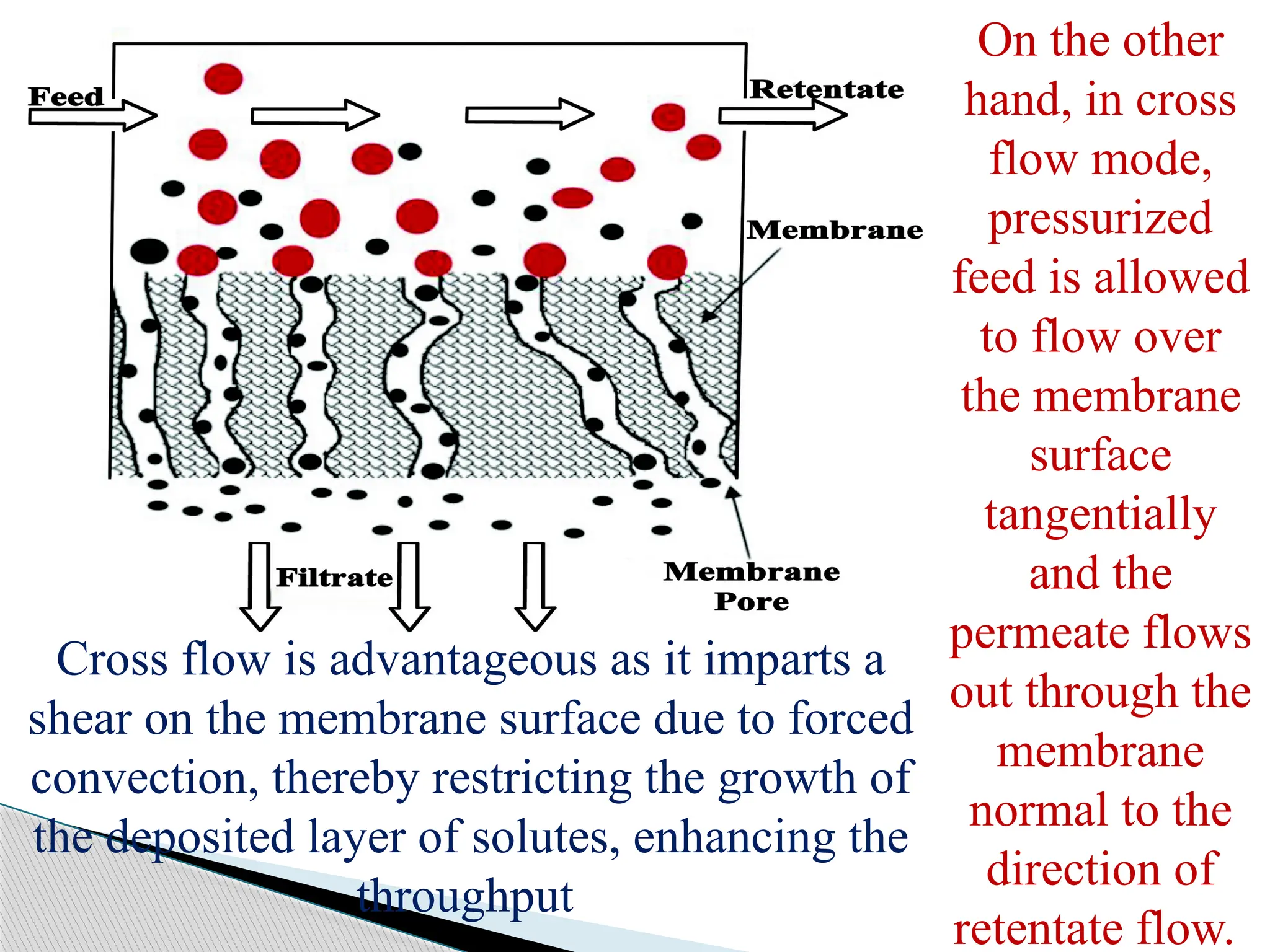
On the other
hand,in cross
flow mode,
pressurized
feed is allowed
to flow over
the membrane
surface
tangentially
and the
permeate flows
out through the
membrane
normal to the
direction of
retentate flow.
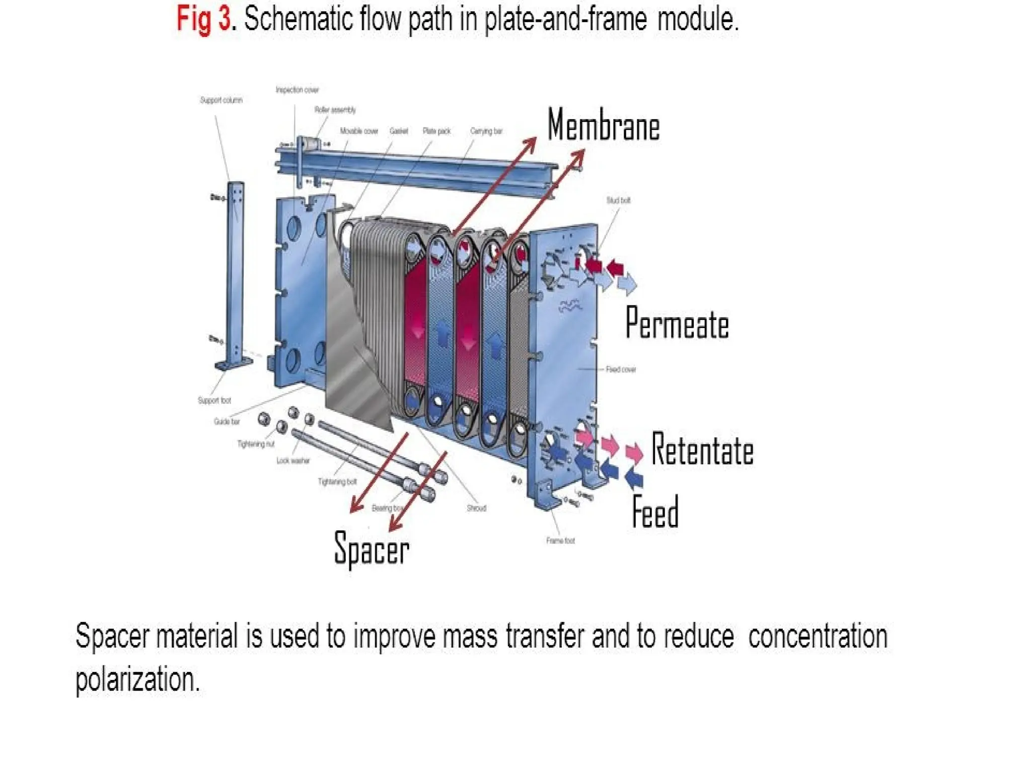
Cross flow is advantageous as it imparts a
shear on the membrane surface due to forced
convection, thereby restricting the growth of
the deposited layer of solutes, enhancing the
throughput
33.
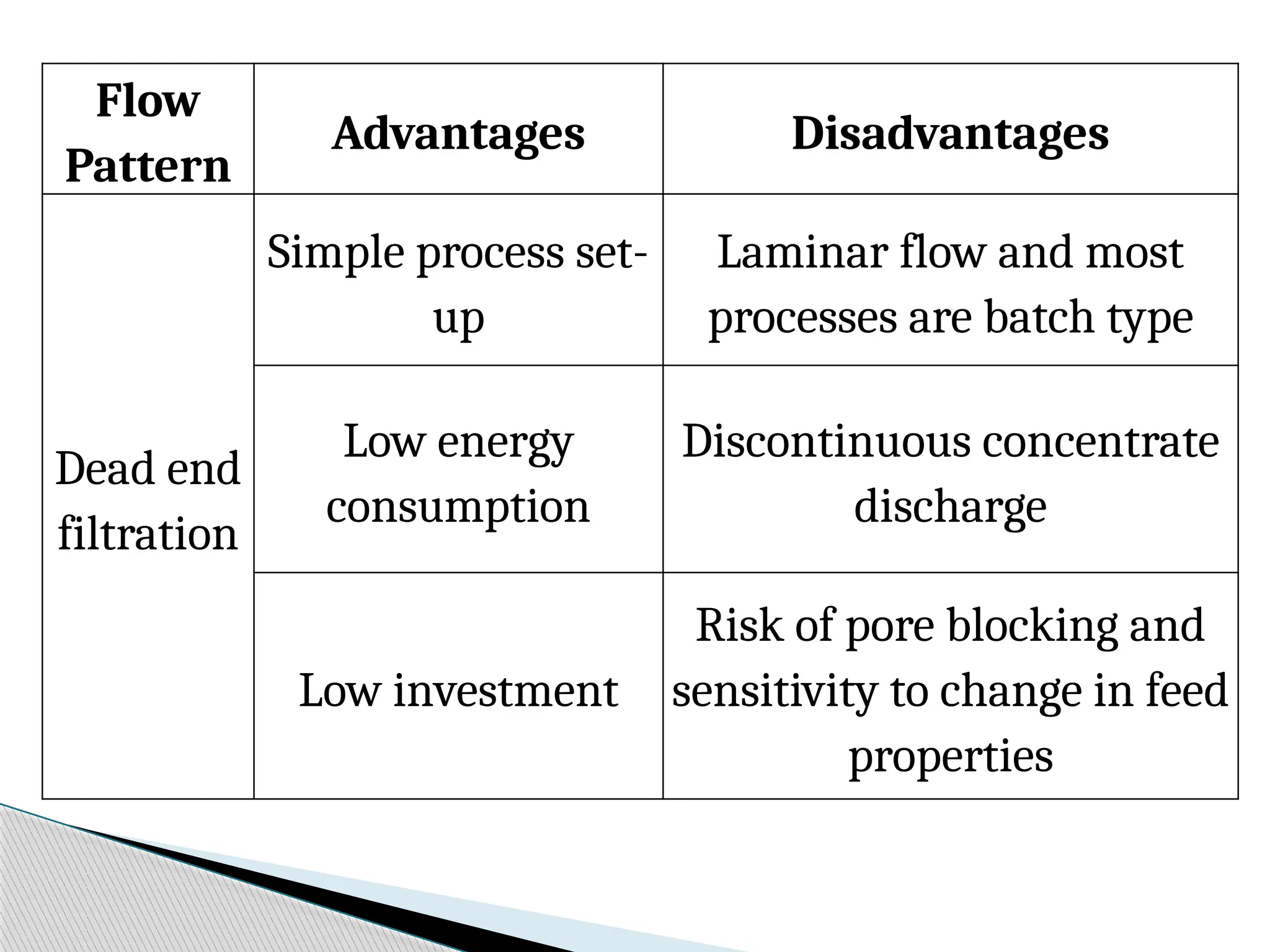
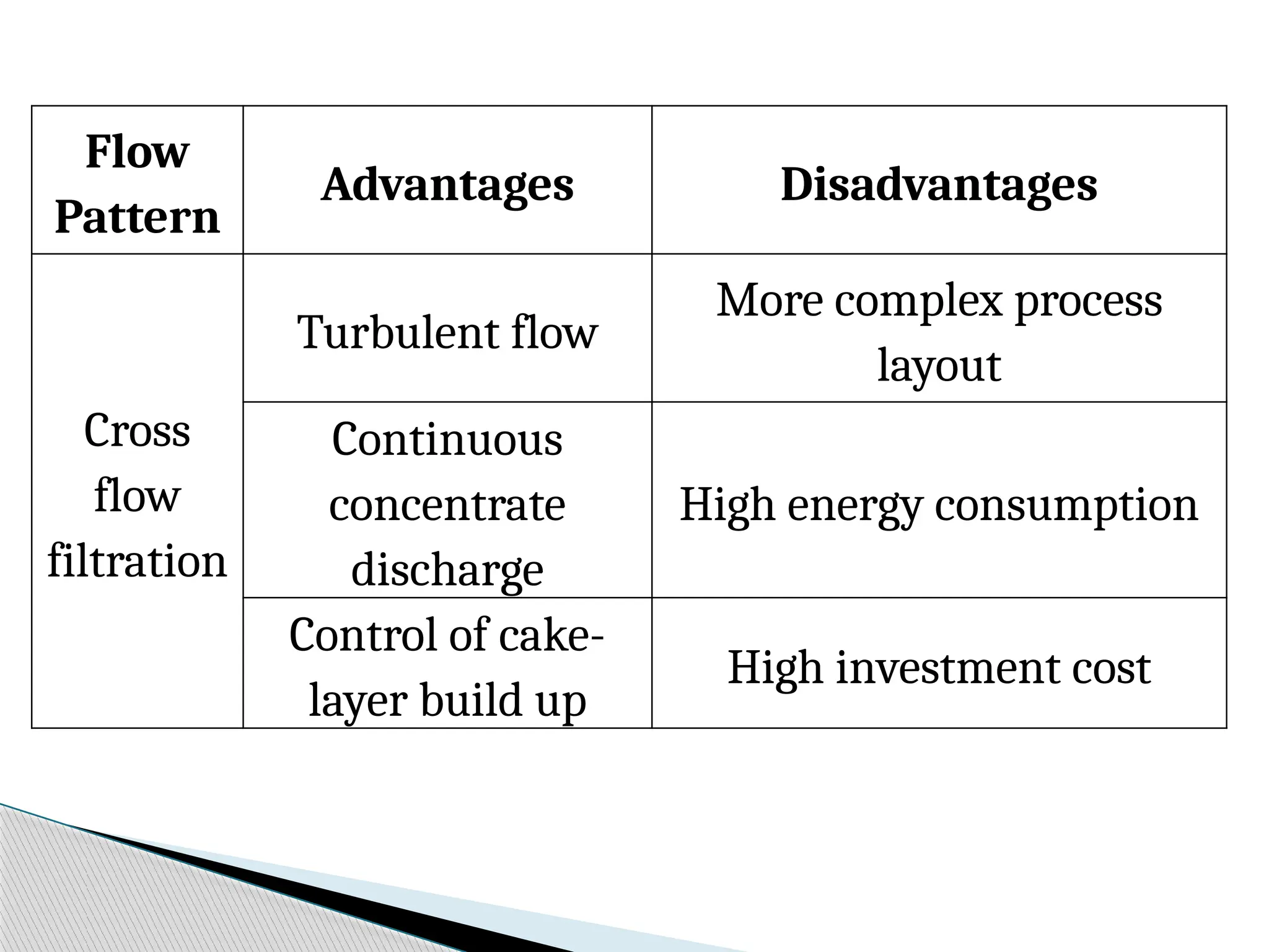
Flow
Pattern
Advantages Disadvantages
Dead end
filtration
Simpleprocess set-
up
Laminar flow and most
processes are batch type
Low energy
consumption
Discontinuous concentrate
discharge
Low investment
Risk of pore blocking and
sensitivity to change in feed
properties
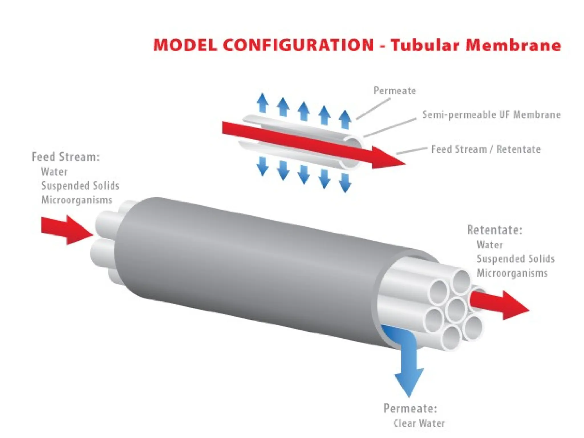
Membrane modules
Thepractical equipment where the actual
membrane based separation occurs is known as
membrane modules. Housing of the membrane is
known as membrane modules and these modules
are generally expensive because they need to be
leak-proof even at high operating pressure.
The basic aim of development of these modules is to
provide maximum filtration area in smaller volume,
so that the design becomes compact, space saving
and the permeate flux i.e., the productivity of the
system is maximum.
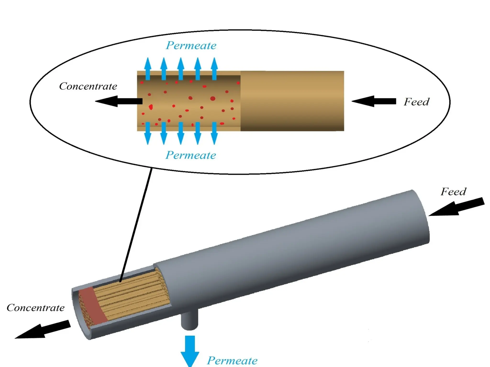
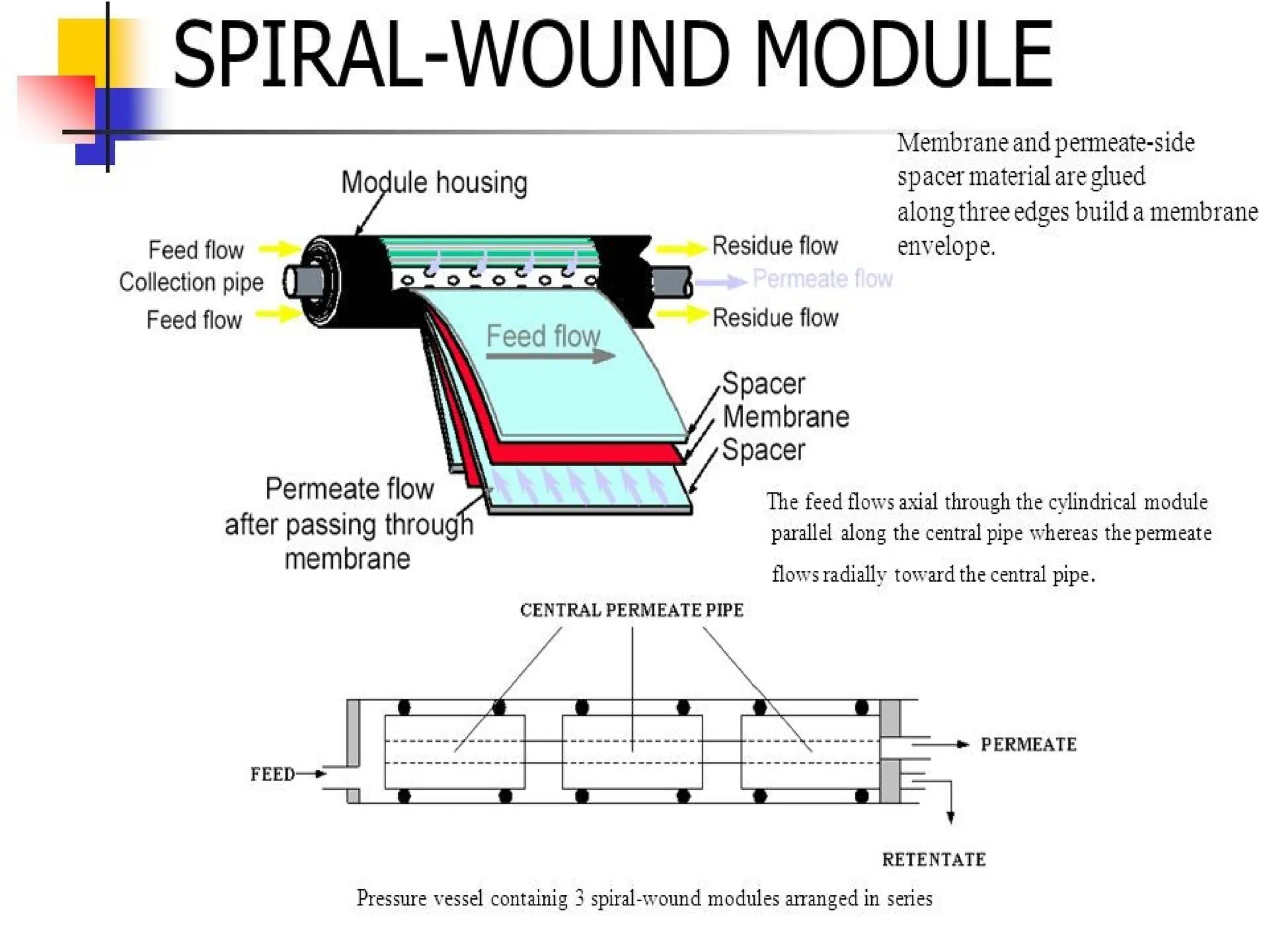
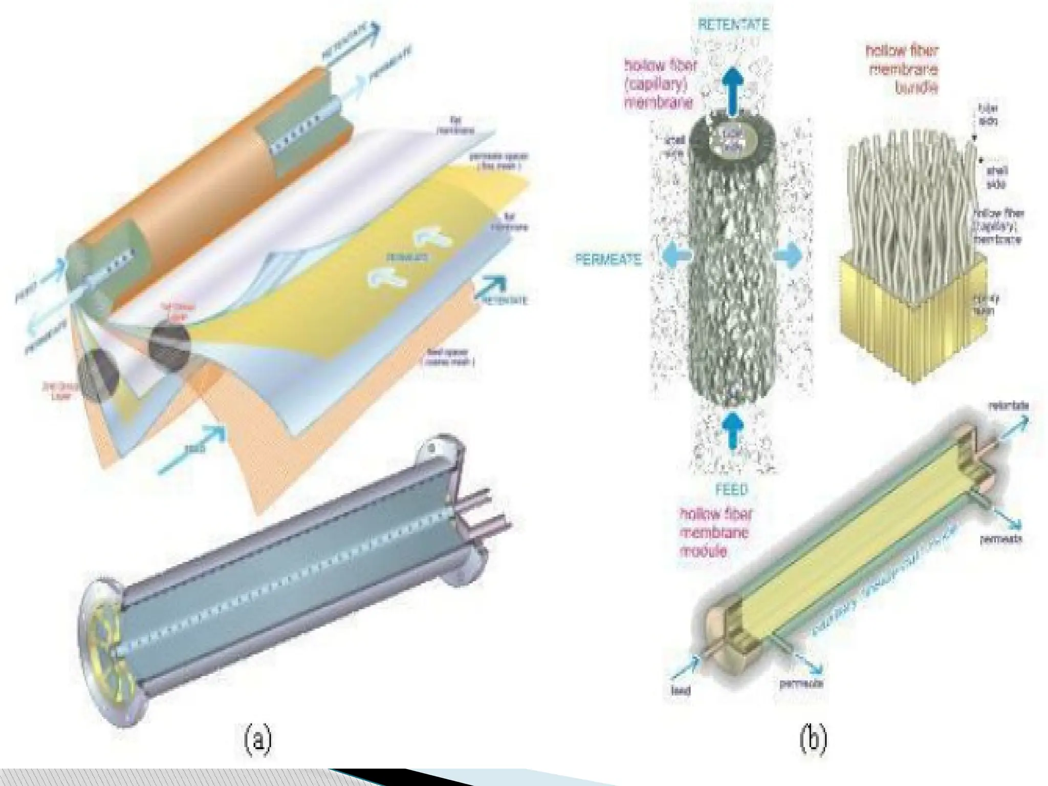
36.
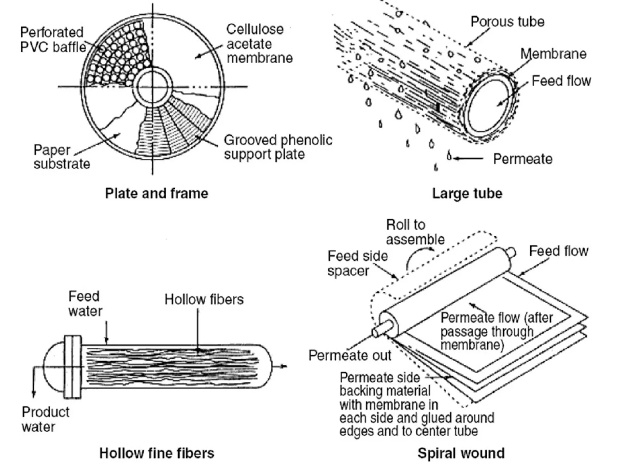
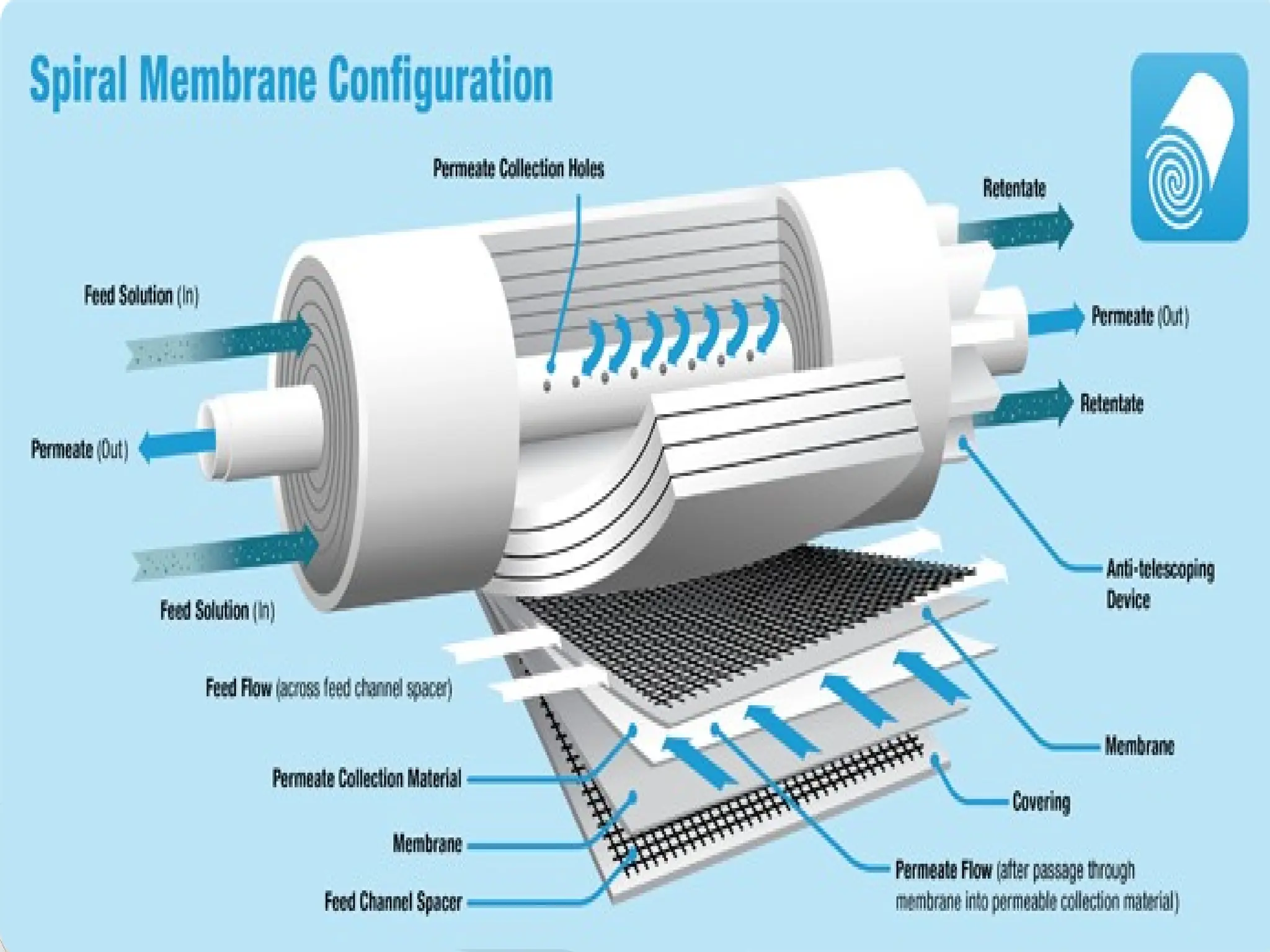
Commonly used membranemodules are
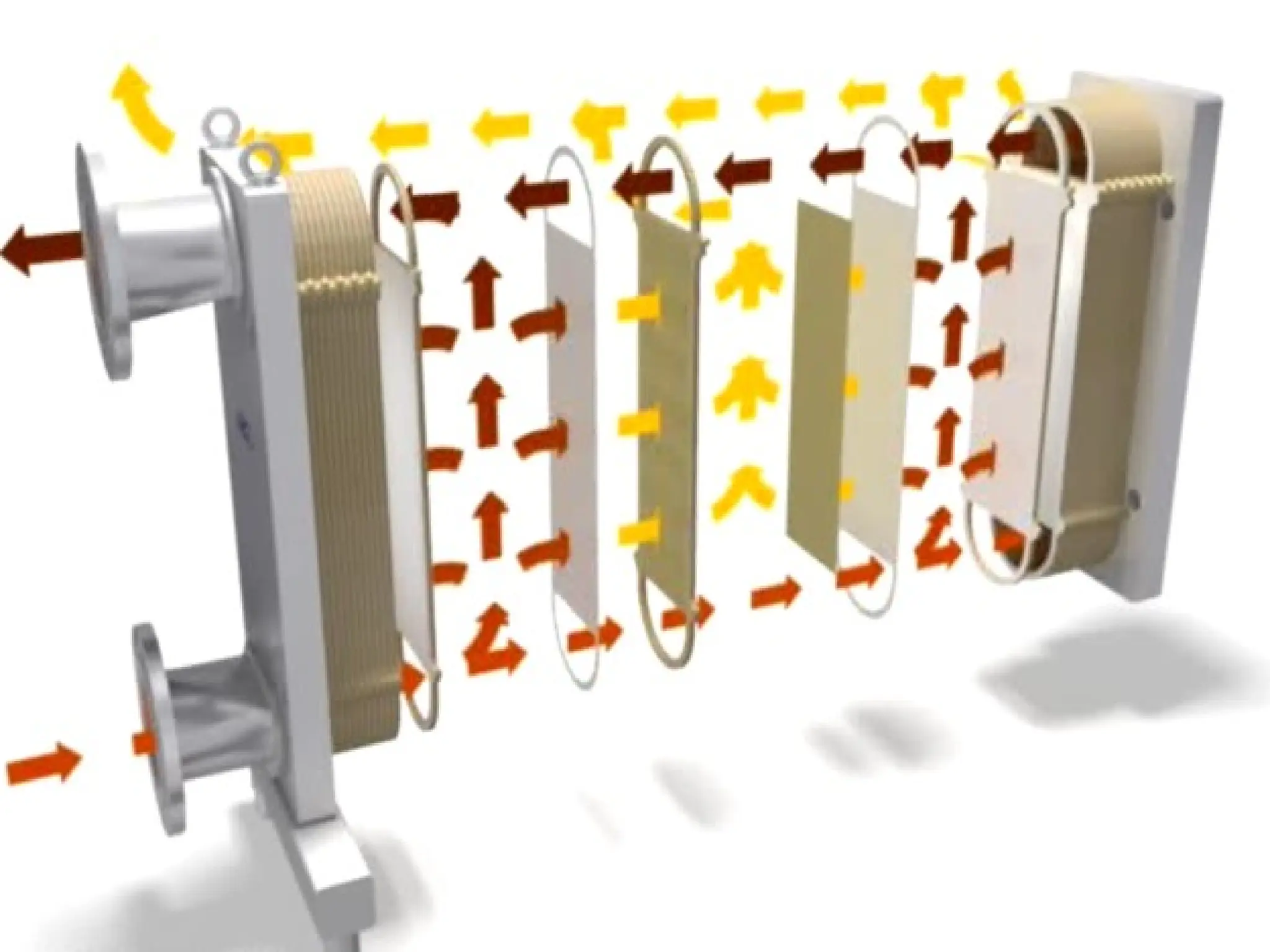
Plate and Frame,
Hollow Fiber Module,
Spiral Wound Module and
Tubular Module.
Suitable module is used for separation or
clarification purpose based on the operating
conditions and process parameters
45.
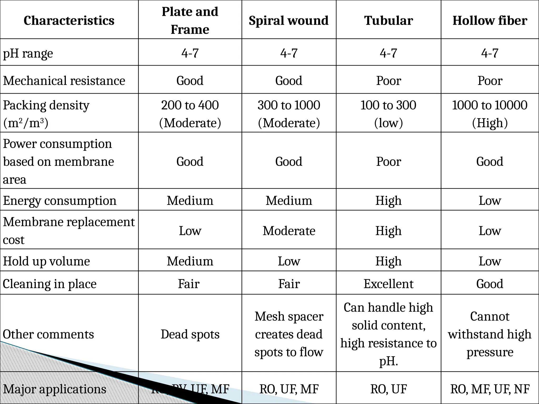
Characteristics
Plate and
Frame
Spiral woundTubular Hollow fiber
pH range 4-7 4-7 4-7 4-7
Mechanical resistance Good Good Poor Poor
Packing density
(m2
/m3
)
200 to 400
(Moderate)
300 to 1000
(Moderate)
100 to 300
(low)
1000 to 10000
(High)
Power consumption
based on membrane
area
Good Good Poor Good
Energy consumption Medium Medium High Low
Membrane replacement
cost
Low Moderate High Low
Hold up volume Medium Low High Low
Cleaning in place Fair Fair Excellent Good
Other comments Dead spots
Mesh spacer
creates dead
spots to flow
Can handle high
solid content,
high resistance to
pH.
Cannot
withstand high
pressure
Major applications RO, PV, UF, MF RO, UF, MF RO, UF RO, MF, UF, NF
46.
Driving Forces inMembrane Separation
Processes
Separation in membrane is the result of differences
in the transport rates of chemical species through it.
Transport rate is determined by the driving force
acting on individual components, their mobility,
concentration of solute in membrane phase, etc.
Mobility : Depending on solute size and
structure of membrane.
Concentration : Chemical compatibility of
solute & interface material.
47.
Categorization of variousmembrane
based processes
Among the different membrane separation
techniques, pressure-driven processes are simplest
in terms of their ability to separate particulates in
liquid and gas feed streams according to size.
Through utilizing pressure as a driving force for
separation, with a membrane acting as a
semipermeable barrier, pressure-driven processes
are also associated with higher flux compared to
their thermal and concentration-based separation
counterparts.
48.
Types ofpressure-driven membrane
separation techniques are categorized
according to membrane pore size, which, in
turn, dictates the degree of separation
achieved.
These categories are
Microfiltration (MF),
Ultrafiltration (UF),
Nanofiltration (NF), and
Reverse osmosis (RO).
49.
Reverse Osmosis
Reverseosmosis (RO) membranes contain the smallest
pores of the pressure-driven membrane processes and
are capable of retaining all dissolved particles within a
feed stream, including monovalent ions.
This degree of separation results in a permeate
consisting of a pure solvent, which, in many cases, is
water.
Separation using RO is accomplished not only through
size exclusion but utilizes a diffusive mechanism as well.
50.
• Pore sizeis very small (2-10A0
), therefore, it will be
used for separation of very low molecular size
material (we are going to separate small solute
particles which will be having a molecular weight
typically less than 100, that means various types of
salts, e.g.: Sodium chloride have molecular weight
58.5).
• Since the pore size is very small, the osmotic pressure
will become predominant.
• As osmotic pressure has two characteristics: It is
directly proportional to the concentration (that’s why
it is known as the colligative property) and inversely
proportional to the molecular weight.
51.
• Therefore, ifwe encounter solute which is having very
low molecular weight, then osmotic pressure become
very high (and for higher molecular solute, osmotic
pressure becomes low, it is not very important).
Therefore, in this case, we have to apply pressure in
the feed side to overcome the osmotic pressure. Then
only the first step of permeate coming in the other in
the downstream side. So, pressure requirement in
reverse osmosis becomes highest. Pressure
requirement is in the order of 25-40 atmosphere.
• The most common applications for RO are in the
preparation of drinking water and beverage
concentration.
52.
Nano Filtration
Bothsize and charge play a role in nanofiltration (NF)
separation processes (in contrast to MF and UF, in which
solutes are separated according to size).
Pore size are slightly higher than RO.
With a average pore size between 5 - 20A0
, NF
membranes are capable of retaining low molecular
weight, uncharged solutes, such as sugars and other
organic molecules.
Since the pore size is higher, therefore, we can separate
the particles of higher molecular weight (in the range of
200-1000).
53.
As thepore size is higher and the molecular weight of
the particle to be separated is higher, therefore,
pressure requirements will be slightly lower in this
case.
It causes a partial retention of salts
NF membranes also retain charged species, such as
polyvalent ions and large monovalent ions, whereas
smaller monovalent species pass through.
Applications for NF membranes range from
theremoval of natural organic matter in wastewater
treatment, hardness reduction in water purification,
and whey demineralization in dairy processing.
54.
The applicationsof nano filtration are dyes
separation: dye molecules have the molecular weight
in the range of 200-900. These are various dye
solution / dyes, which is having molecular weight in
these ranges.
The small low molecular weight organics like,
polyphenols having a typical molecular weight
between 400-600 and they can be separated by the
nano filtration completely so, we can select
appropriate cut off or characterized nano filtration
membrane and can separate the polyphenols, dye.
Therefore, nano filtration has tremendous application
in the in treatment of the textile effluent. So, it can
separate out the dyes.
55.
Ultra Filtration
Within the family of pressure-driven membrane
processes, ultrafiltration (UF) lies between
microfiltration and nanofiltration in terms of pore size,
which can range from 20 - 100A0
.
Molecular weight of solutes that is separated will be in
the range of 1000-105
.
Since, we are talking about the higher pore sized and
separation of higher molecular solute, the pressure
requirements will be less and it will be 6-8 atmosphere.
Transport mechanism is, a mixture of convection (main
mechanism) as diffusion.
56.
It hasa wide variety of application, e.g., separation of
high molecular weight protein.
This size range allows for the concentration of high
molecular weight proteins, macromolecules, and other
small, suspended solids.
In contrast to MF, UF membranes are categorized with
respect to their molecular weight cutoff, i.e., their
ability to retain a molecule of a given size, rather than
by the size of their pores.
Nevertheless, the pore size range of UF membranes
makes them well-suited for use in a wide variety of
ultrafiltration applications across multiple industries.
57.
In theautomotive industry, UF is used in the recovery
of undeposited paint for reuse in the electrocoating
process.
In the food and beverage industries, it is used in
applications ranging from the concentration of whey
protein to the clarification of fruit juices.
Protein separation purification or fractionation blood,
red blood cells, polymeric solution separation on
purification of polymeric solution, it can be done under
ultra filtration process.
58.
Membrane canbe utilized for separation / purification
/ fractionation. All the purpose can be solved.
One can separated out particular solute, one can
purified a particular solute by separating, and one can
fractionated.
Suppose, we are having 2 solutes, (Let say molecular
weight 60,000 and another solute having molecular
weight 7000) then we can select a particular
membrane. Let say, 40,000 or 30,000 cut off that will
retain in the higher molecular solute, in the upstream
side and it will allow lower molecular solute in the
downstream side, so, it can be utilized for the case of
fractionation.
59.
Micro Filtration
Microfiltration(MF) lies on the upper end of the
spectrum of pressure-driven membrane techniques, with
membranes containing the largest pore size of the
aforementioned processes.
Pore size is very high (in the order of more than 1000 A0
),
0.1m, 0.2 m, 1 m, 2 m like that, and molecular
weight of solutes to be separated is greater than 1 lakh.
Therefore, pressure requirement is lower (2 to 4 atm). Ex:
filtration of clay solution, latex, paint etc.
As the pore size of the membrane becomes higher, the
pressure requirement is going to be lower and lower.
Therefore, we do not require very high pressure for
effect.
60.
As weare talking about the low pore size membrane,
then the osmotic pressure becomes pretty important
and becomes very high.
It is often used as a precursor step to downstream
filtration applications in order to achieve the desired
degree of separation within a given feed stream.
Due to the larger pore size of MF membranes, many of
these processes are capable of being run at lower
pressures than those with membranes containing
smaller pores. Common MF applications involve the
separation of large macromolecules in clarification
steps, such as in the removal of bacteria from cellular
broths and in fat removal processes in the dairy
industry.
61.
Osmotic Pressure ()
•Suppose we are having a chamber separate by a semi
permeable barrier (between two solutes, it will selective
to a particular species, i.e., it will allows water, but it will
not allows salt)
• Let say some volume of water in both chambers. One is
solution side (add some salt here) and another is solvent
(pure water) side. Then the solvent (water) activity is
less in the solution chamber and more in the solvent
side, therefore, water will be transported from the
solvent to the solution side, because driving force of
chemical potential gradient.
62.
• So, aftersome time, the equilibrium will be taking
place, (it may be after 24 hours, may be occur 36 hour)
finally, the level of water under solvent side will go
down and level of water in the solution side will go up
that will calls a hydrostatic development of a
hydrostatic head (gh) and this is nothing but the
osmotic pressure.
• As osmotic pressure is colligative property (Colligative
property means, any property means, any property that
will depend on the amount of solute present in the
system). It mean, if we increase the concentration of
the salt in the solution side, the concentration
difference will be higher, so water activity difference of
activity higher, so more water will be permeating from
the solvent side to the solution side.
63.
• In thatcase, the hydrostatic pressure (gh) between
the final equilibrium position in the solution side and
solvent side will be more, so osmotic pressure develop
will be more.
• Therefore, osmotic pressure is directly proportional to
the concentration of the solute and inversely
proportional to the molecular weight of the solute.
Therefore, for solute having lower molecular weight,
the osmotic pressure will be very high.
• Therefore, for dilute solution = RTC / M; this is
known as Vant Hoff relation. This is for the monovalent
salt.
• The relation for the divalent salt : = (+
- -
)
RTC / M, i.e., for CaCl2
these basically valence, +
is 2
and Cl-
is 1.
64.
Note
• Any solutionhave its own osmotic pressure, for
example, if we have a glass of saline solution, or
sugar solution, it will be having its own osmotic
pressure, but we cannot realize the osmotic
pressure, because osmotic pressure can be realized
if one only if, semi permeable barrier is present in
the solution. Otherwise, we cannot realize the
osmotic pressure. That’s why, whenever we are
talking about membrane base separation process,
since, a semi permeable barrier is present in the
solution itself. The osmotic pressure becomes very
important.
65.
• When wedrink a glass of saline water, it is
having osmotic pressure, but before drinking it
we cannot feel it, but when it goes inside, the
vessels etc, in the body are basically semi
permeable barrier; so, it creates an increasing
blood pressure therefore, the doctor also, advise
do not take saline water or decrease the intake
of salt, because it will increase osmotic pressure
in the blood vessels and it may ruptured.
66.
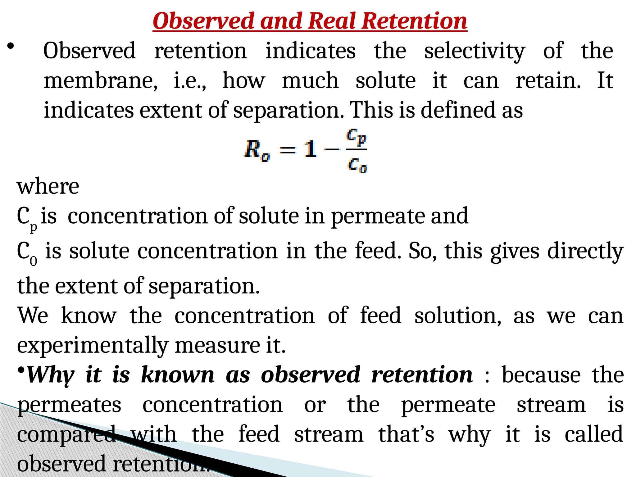
Observed and RealRetention
• Observed retention indicates the selectivity of the
membrane, i.e., how much solute it can retain. It
indicates extent of separation. This is defined as
where
Cp
is concentration of solute in permeate and
C0
is solute concentration in the feed. So, this gives directly
the extent of separation.
We know the concentration of feed solution, as we can
experimentally measure it.
•Why it is known as observed retention : because the
permeates concentration or the permeate stream is
compared with the feed stream that’s why it is called
observed retention.
67.
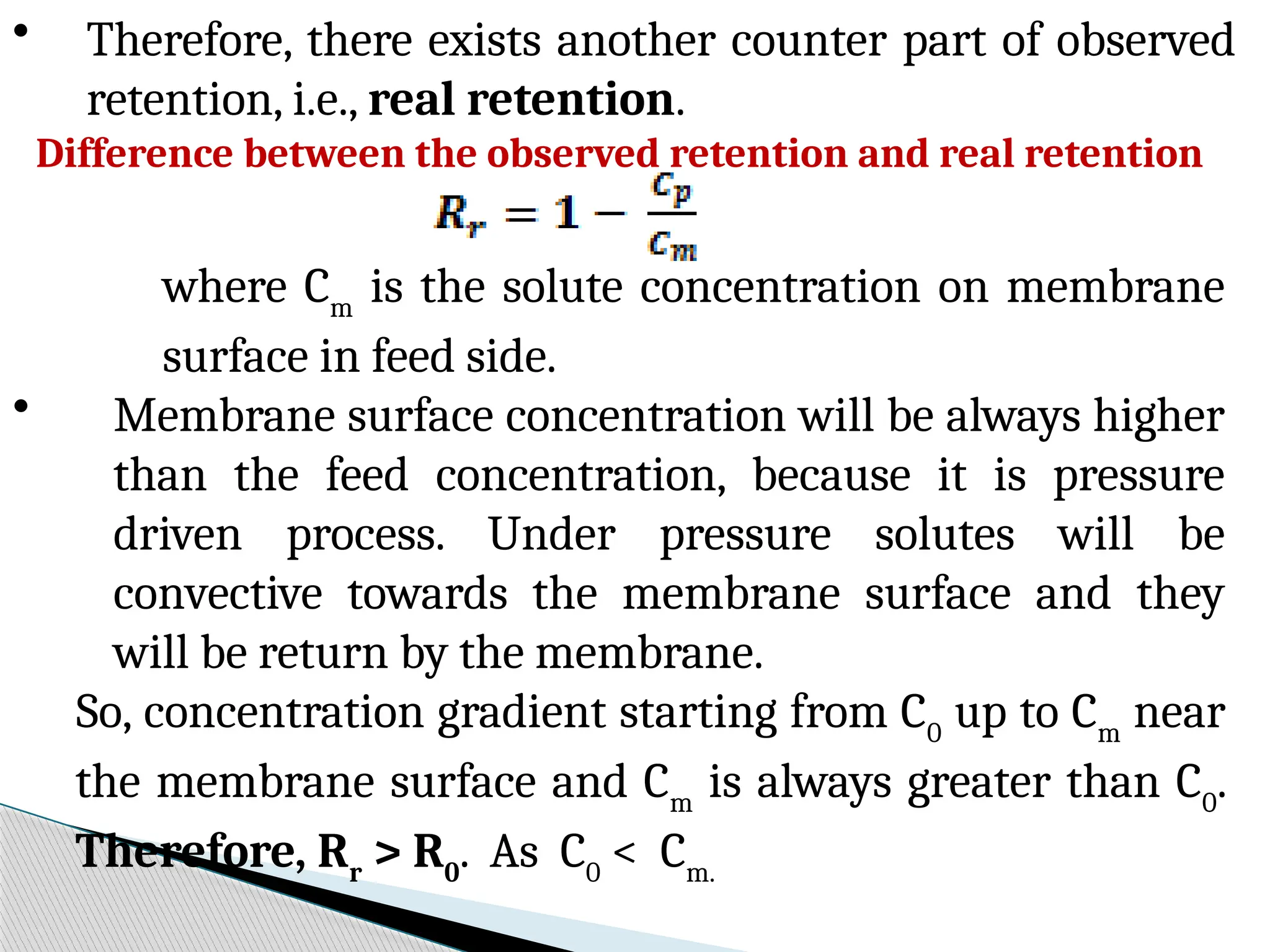
• Therefore, thereexists another counter part of observed
retention, i.e., real retention.
Difference between the observed retention and real retention
where Cm
is the solute concentration on membrane
surface in feed side.
• Membrane surface concentration will be always higher
than the feed concentration, because it is pressure
driven process. Under pressure solutes will be
convective towards the membrane surface and they
will be return by the membrane.
So, concentration gradient starting from C0
up to Cm
near
the membrane surface and Cm
is always greater than C0
.
Therefore, Rr
> R0
. As C0
< Cm.
68.
Dialysis
Dialysis isa separation technique that relies on selective
diffusion of molecules across a semi-permeable
membrane to separate molecules based on size.
In the feed side, a specific set of solutes are permeated
through the membrane (which contains pores of a
manufactured size-range) to the other side.
The upstream feed is known as the feed side and the
downstream is known as the dialysate.
Typically, dialysate stream is pure distilled water. Thus,
the concentration gradient between the two streams is
the maximum.
69.
The transportis effected by the concentration gradient
between two streams.
The duration of separation entirely depends on the rate
of the solutes through the membrane.
Sample molecules that are larger than the pores are
retained on the sample side of the membrane, but small
molecules pass through the membrane, reducing the
concentration of those molecules in the sample.
Alternatively, desired components in the external buffer
solution can be slowly brought into the sample.
Dialysis is used for a wide variety of applications:
desalting, buffer exchange, removal of labeling reagents,
drug binding studies, cell growth and feeding, virus
purification, and blood treatment. An example is removal
of urea, creatinin from blood stream.
70.
Electro Dialysis (ED)
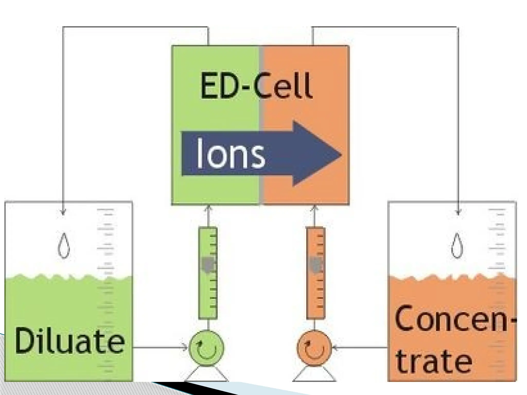
Electro Dialysis (ED) is a membrane process, during
which ions are transported through semi permeable
membrane, under the influence of an electric potential.
The membranes are cation- or anion-selective, which
basically means that either positive ions or negative ions
will flow through.
Cation-selective membranes are polyelectrolytes with
negatively charged matter, which rejects negatively
charged ions and allows positively charged ions to flow
through.
72.
By placingmultiple membranes in a row, which
alternately allow positively or negatively charged ions to
flow through, the ions can be removed from wastewater.
In some columns concentration of ions will take place
and in other columns ions will be removed. The
concentrated saltwater flow is circulated until it has
reached a value that enables precipitation. At this point
the flow is discharged.
This technique can be applied to remove ions from
water. Particles that do not carry an electrical charge are
not removed.
73.
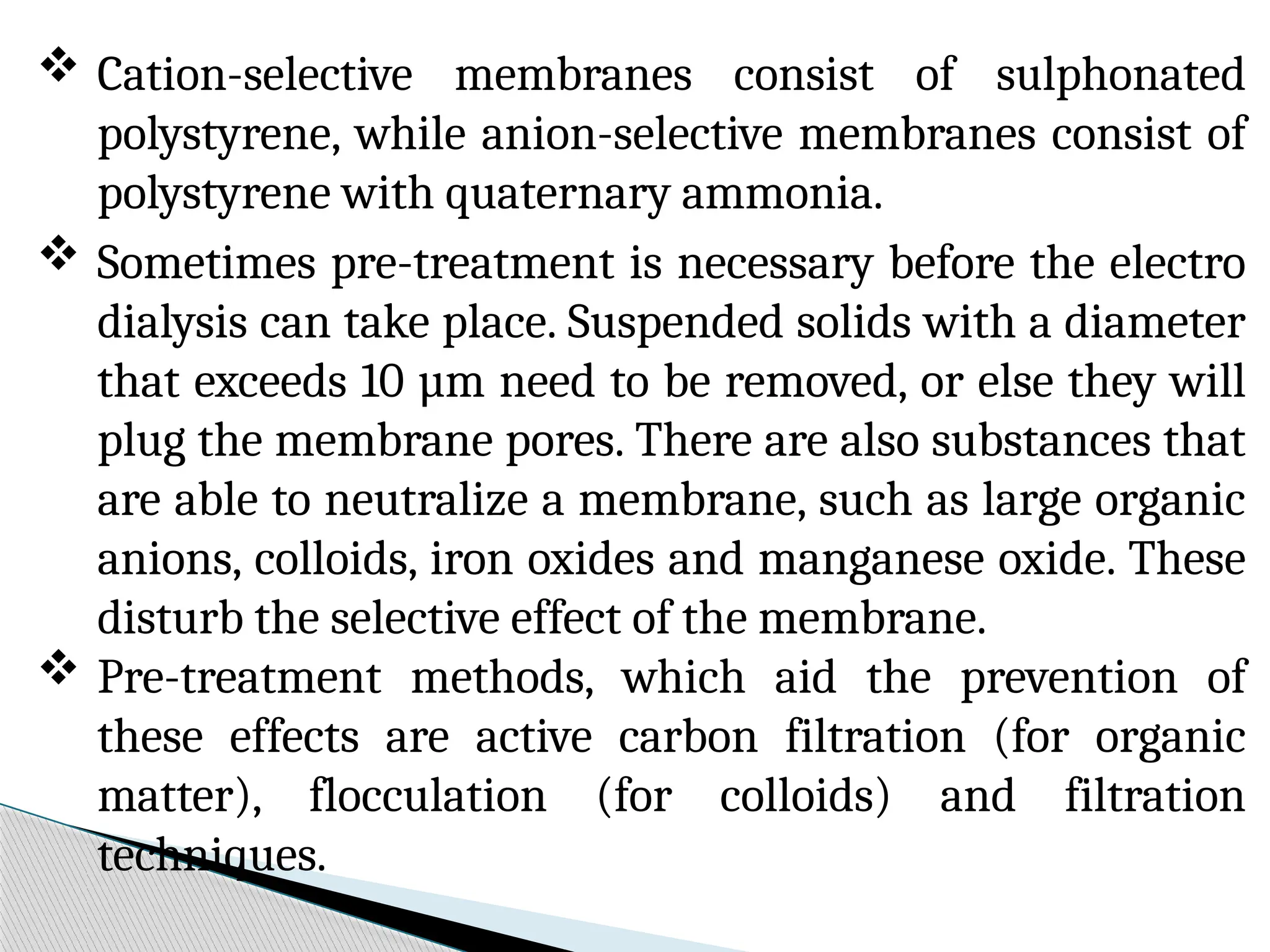
Cation-selective membranesconsist of sulphonated
polystyrene, while anion-selective membranes consist of
polystyrene with quaternary ammonia.
Sometimes pre-treatment is necessary before the electro
dialysis can take place. Suspended solids with a diameter
that exceeds 10 µm need to be removed, or else they will
plug the membrane pores. There are also substances that
are able to neutralize a membrane, such as large organic
anions, colloids, iron oxides and manganese oxide. These
disturb the selective effect of the membrane.
Pre-treatment methods, which aid the prevention of
these effects are active carbon filtration (for organic
matter), flocculation (for colloids) and filtration
techniques.
74.
Applications
• Desalination ofsalt water
• Stabilisation of wine
• Whey demineralisation
• Pharmaceutical application
• Pickling bath recycling
75.
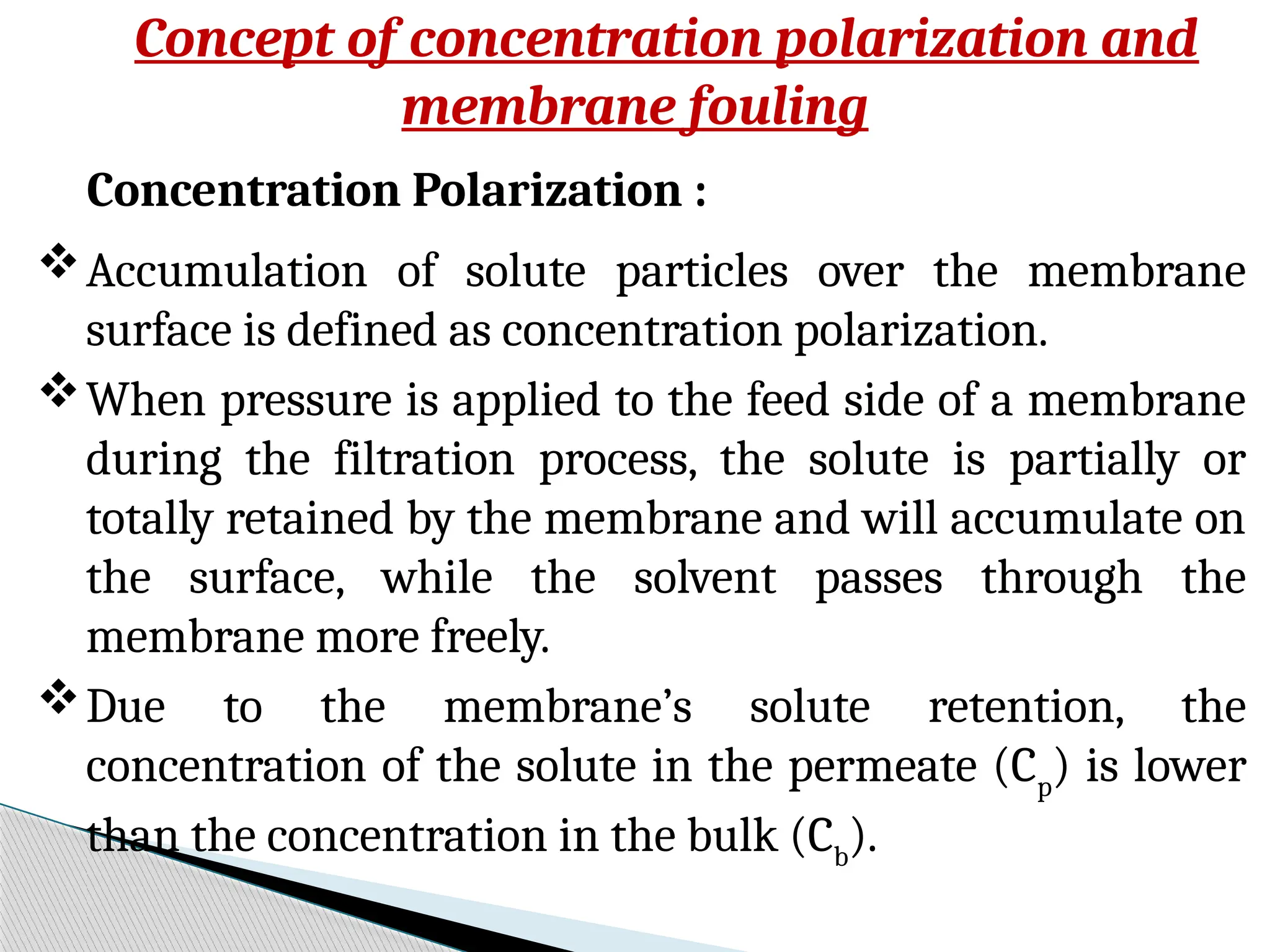
Concept of concentrationpolarization and
membrane fouling
Concentration Polarization :
Accumulation of solute particles over the membrane
surface is defined as concentration polarization.
When pressure is applied to the feed side of a membrane
during the filtration process, the solute is partially or
totally retained by the membrane and will accumulate on
the surface, while the solvent passes through the
membrane more freely.
Due to the membrane’s solute retention, the
concentration of the solute in the permeate (Cp
) is lower
than the concentration in the bulk (Cb
).
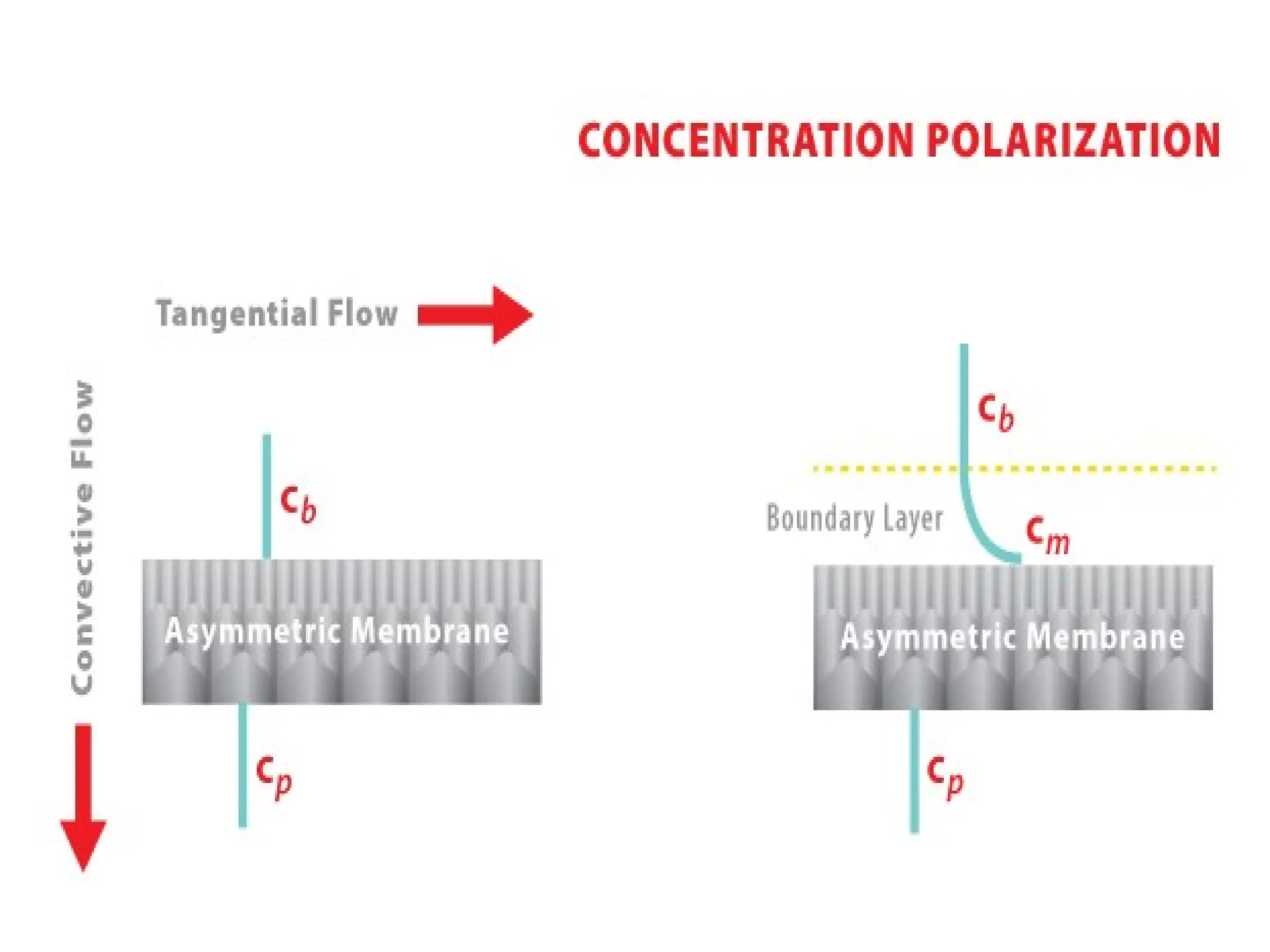
77.
The concentrationof the solute gradually
increases on the surface of the membrane, due
to solute accumulation from convective flow.
At some point, the convective solute flow to the
surface of the membrane will be balanced by the
solute flux through the membrane and the
diffusive flow from the membrane surface to the
bulk.
A concentration polarization profile, in which
the concentration at the membrane surface (Cm
)
is typically higher than the Cb, will be
established in the boundary layer.
78.
Effect of ConcentrationPolarization :
(i) Increase in osmotic pressure of the solution.
(ii) Formation of gel over the membrane surface.
(iii) Increases the viscosity of the solution.
(iv) Solute enters into the pores and pores are blocked
partially or completely.
First phenomena decrease in driving force.
Second and third increases the resistance against flux.
Fourth decreases the membrane permeability. All these
effects lead to decrease in permeate flux.
Concentration polarization cannot be avoided, it can
only be minimized.
79.
Fouling of membrane: Fouling of membrane is of
two types reversible and irreversible.
Reversible Fouling : It can be washed away by
adopting an appropriate cleaning protocol, like
membrane washing. After cleaning, membrane
permeability is restored. Concentration polarization
is reversible fouling.
Irreversible Fouling : In this case, membrane pores
are blocked permanently and they cannot be
removed, even after proper washing. Permeability is
lost permanently.
80.
Other Types
Fouling I: Biofouling- Biofouling is a term for an
undesirable accumulation of microorganisms on the
membrane surface. May be caused by algae growth
stimulated by light, by microorganisms embedded in
the membrane (Biofilms) or module or even by
sulphate reduction by anaerobic bacteria present in
raw waters and eventually causes possible
degradation of membrane material
Particulate fouling is the build-up of particulates
such as suspended solids, colloids and
microorganisms on the membrane
81.
Fouling II :Organic fouling : occurs by the
chemical or physical adsorption of organic
compounds on to the membrane, which may be
followed by the formation of a cake or gel layer
Scaling : It is the term for agglomeration of
particles (salts) on the membrane, which ends up
in a total blockage of the filtration process. This
negative effect can occur during nanofiltration or
reverse osmosis.
82.
Factors Affecting MembraneFouling
• Physicochemical properties of the membrane, e.g.
hydrophobicity, electrostatic charge, reactive groups
• Physicochemical properties of the solute, like molecular
weight, electrostatic charge, hydrophobicity
• The physicochemical parameters of the feed solution, e.g.,
pH, solute concentration
• Membrane morphology, i.e. pore size, pore shape, etc.
• Operating parameters, e.g. TMP, permeate flux, system
Hydrodynamics, etc.
• Concentration polarization
• Membrane operation history
83.
Fouling control
• Preventionof fouling by pre-treatment of feed water
• Optimize nutrient limitation techniques(Biofilms)
• Periodic cleaning (e.g. Backwashing, anti-fouling-agents)
• Optimization of filtration operating conditions
• Improve cleaning efficiency
84.
Industrial Membrane-Separation Processes
(Applications)
1.Reverse osmosis
• Desalinization of brackish water
• Treatment of wastewater to remove a wide variety of
impurities
• Treatment of surface and groundwater
• Concentration of foodstuffs
• Removal of alcohol from beer
2. Dialysis
• Separation of nickel sulfate from sulfuric acid
• Hemodialysis (removal of waste metabolites and excess
body water, and restoration of electrolyte balance in
blood)
85.
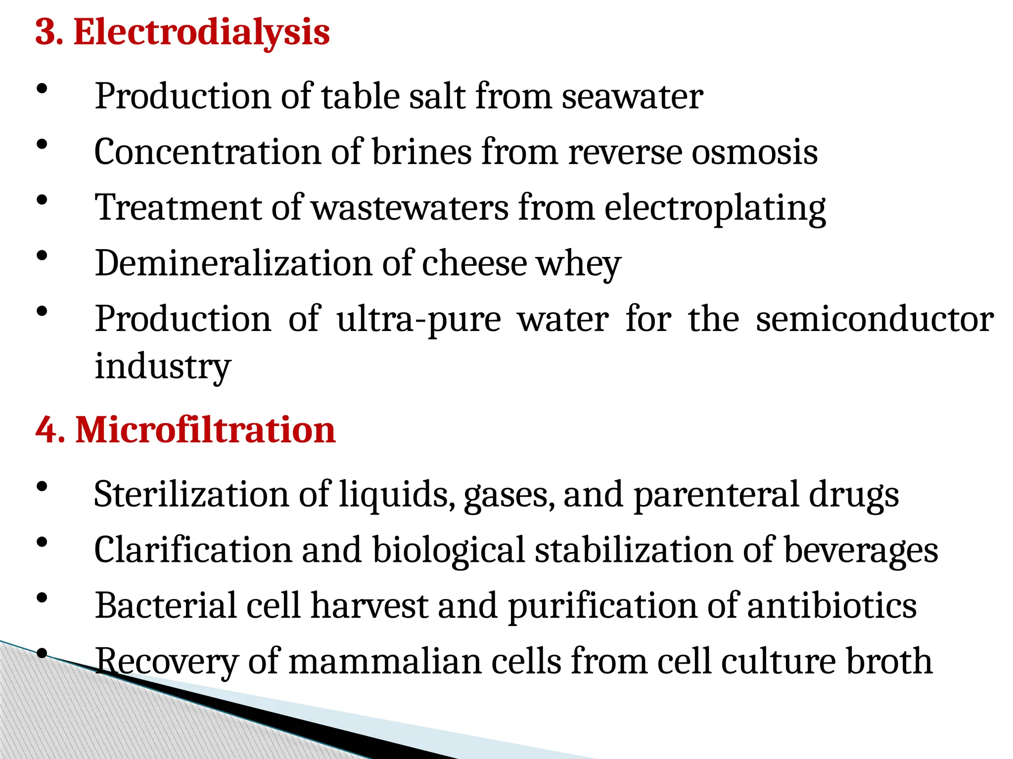
3. Electrodialysis
• Productionof table salt from seawater
• Concentration of brines from reverse osmosis
• Treatment of wastewaters from electroplating
• Demineralization of cheese whey
• Production of ultra-pure water for the semiconductor
industry
4. Microfiltration
• Sterilization of liquids, gases, and parenteral drugs
• Clarification and biological stabilization of beverages
• Bacterial cell harvest and purification of antibiotics
• Recovery of mammalian cells from cell culture broth
86.
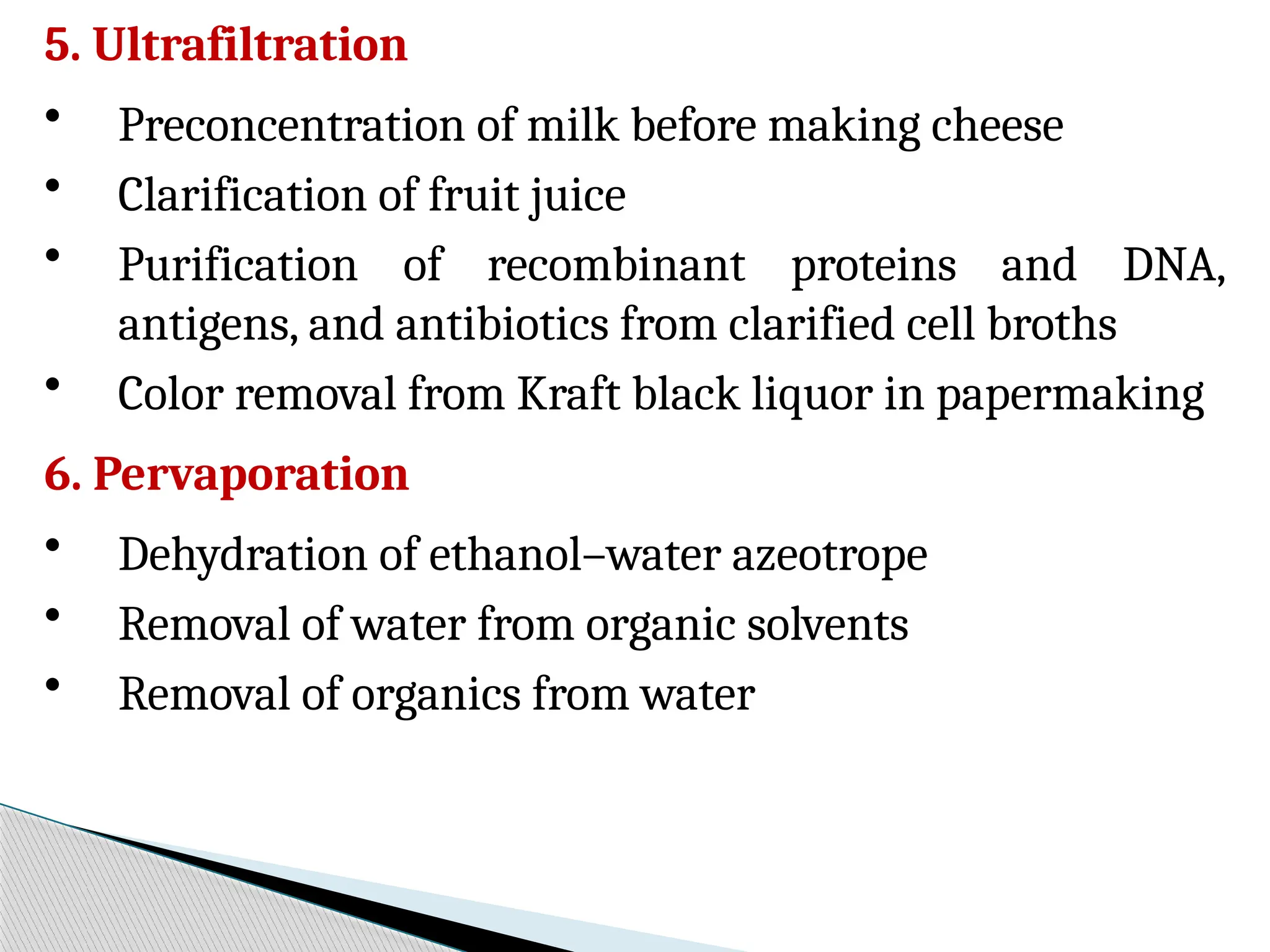
5. Ultrafiltration
• Preconcentrationof milk before making cheese
• Clarification of fruit juice
• Purification of recombinant proteins and DNA,
antigens, and antibiotics from clarified cell broths
• Color removal from Kraft black liquor in papermaking
6. Pervaporation
• Dehydration of ethanol–water azeotrope
• Removal of water from organic solvents
• Removal of organics from water
87.
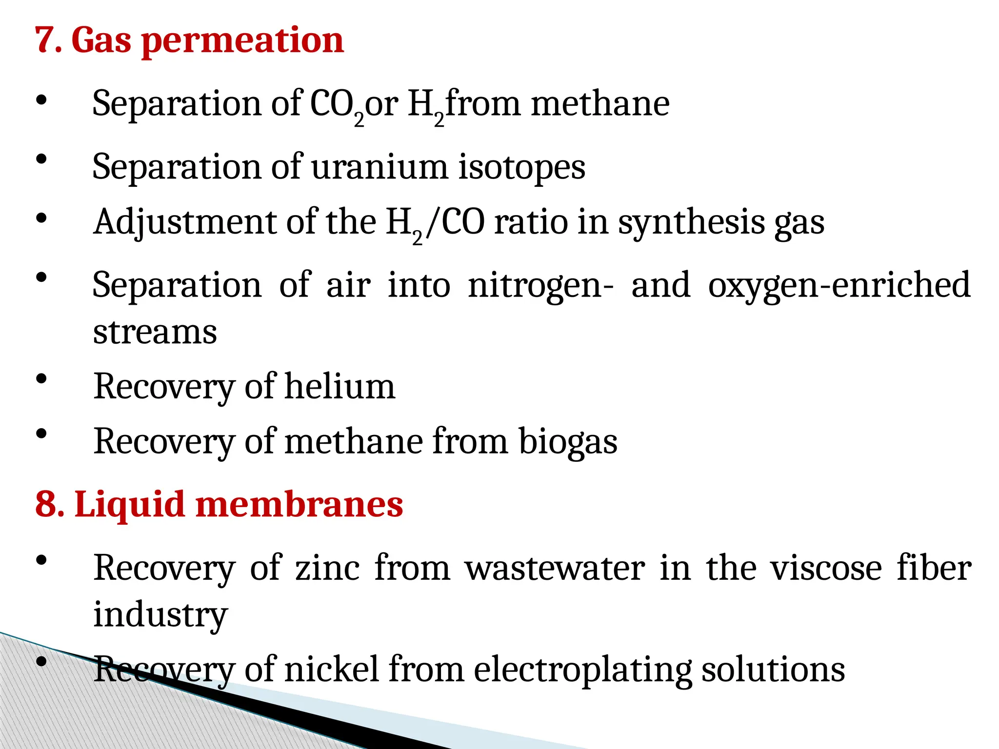
7. Gas permeation
•Separation of CO2
or H2
from methane
• Separation of uranium isotopes
• Adjustment of the H2
/CO ratio in synthesis gas
• Separation of air into nitrogen- and oxygen-enriched
streams
• Recovery of helium
• Recovery of methane from biogas
8. Liquid membranes
• Recovery of zinc from wastewater in the viscose fiber
industry
• Recovery of nickel from electroplating solutions
88.
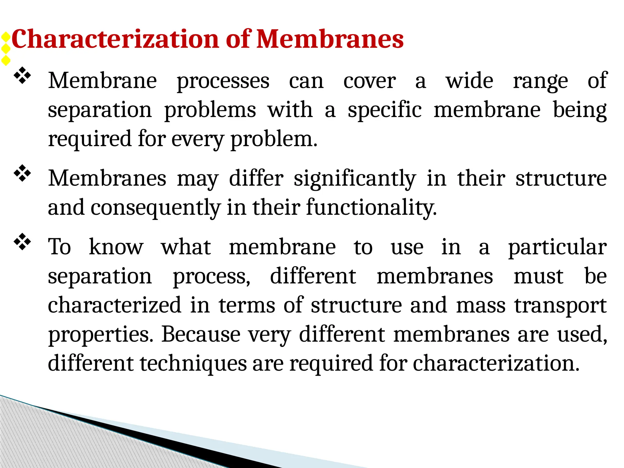
Characterization of Membranes
Membrane processes can cover a wide range of
separation problems with a specific membrane being
required for every problem.
Membranes may differ significantly in their structure
and consequently in their functionality.
To know what membrane to use in a particular
separation process, different membranes must be
characterized in terms of structure and mass transport
properties. Because very different membranes are used,
different techniques are required for characterization.
89.
Membrane characterizationis a very important
part of membrane research and development
because the design of membrane processes and
systems depends on reliable data relating to
membrane properties.
1. Characterization of Porous membranes
2. Characterization of Dense, Homogeneous
membranes
3. Characterization of Charged membranes
90.
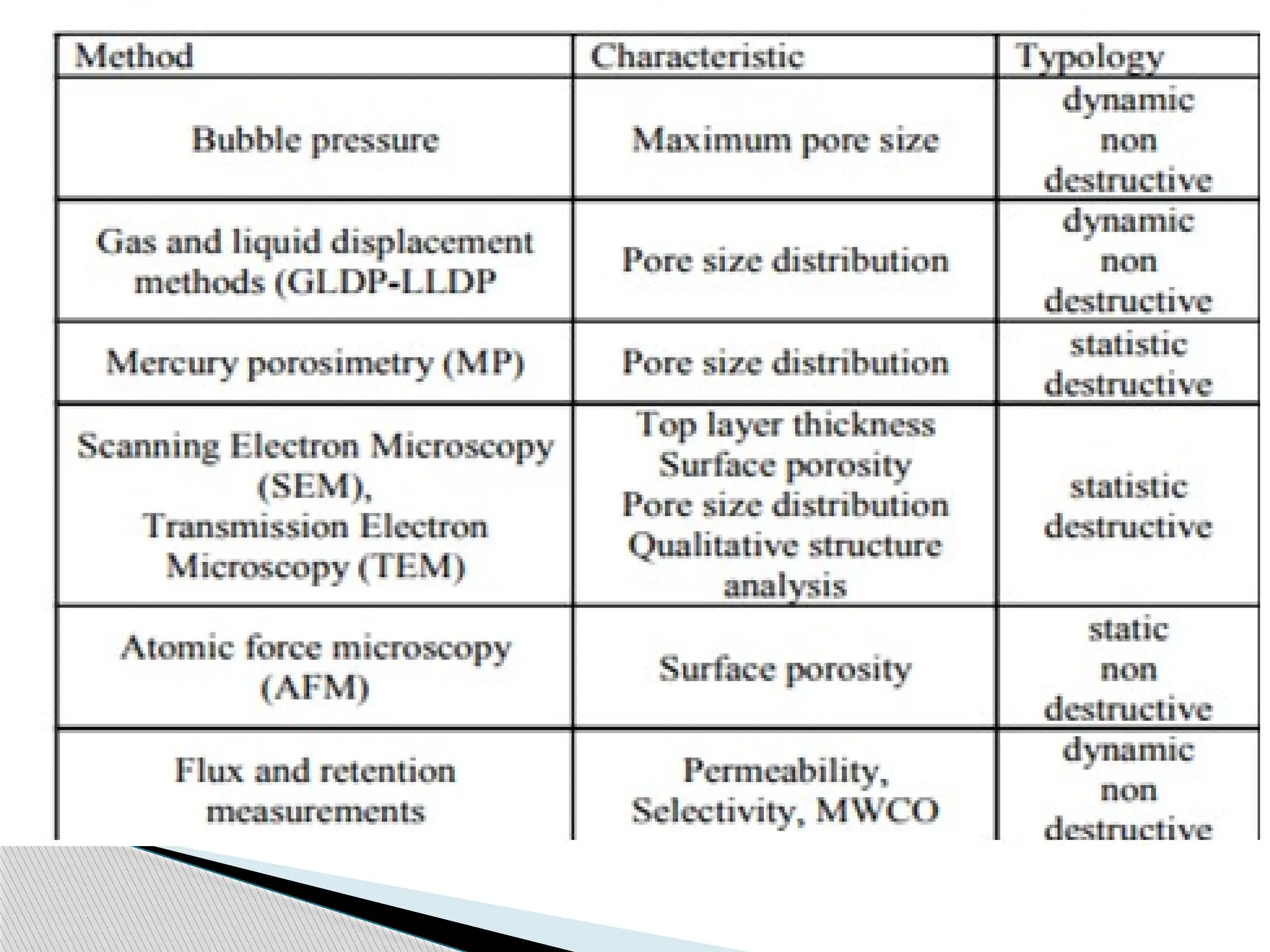
Characterization of PorousMembranes
Porous micro- or ultrafiltration membranes are generally
characterized in terms of their trans-membrane flux, pore
size, pore size distribution, and molecular mass cut-off.
Electron Microscopy : The structure of porous membranes
can be determined by electron microscopy. Scanning
Electron Microscopy (SEM) gives an especially clear picture
of membrane structure and requires minimum sample
preparation; however, resolution is limited to about 50-nm.
Higher resolution can be obtained with Transmission
Electron Microscopy (TEM), but sample preparation is
significantly more complex and the structure is not nearly as
clear as that obtained by scanning electron microscopy.
91.
Bubble-Point Test
The"bubble-point" test is a simple method for
determining the maximum pore size of a membrane.
One side of the membrane is filled with liquid such as
water, although i-propanol is often used as the standard
liquid.
If the other side of the membrane is exposed to air at a
certain pressure, air bubbles will penetrate through the
pores of the membrane when the radius of the air bubble
is equal to the radius of the pore.
The pressure needed to penetrate a pore is inversely
proportional to pore size.
Thus, penetration occurs first through the largest pores.
92.
When thepressure is increased further, pores with
smaller diameters are also penetrated.
Because the surface tension between water and air is
rather high, high pressure is required for the
determination of small pores.
In practice, pore sizes between 0.1 and 10 mm are
determined by hydrostatic pressures of 1500 - 15 kPa.
The main application of the bubble-point test is to
determine pinholes and leaks in micro- and
ultrafiltration membranes and modules.
93.
Filtration Tests
Infiltration tests, trans-membrane flux and membrane
solute retention are determined.
To avoid the influence of concentration polarization or
any other boundary layer phenomenon, the trans-
membrane flux is generally measured as a function of
applied hydrostatic pressure with ultra-pure water.
Membrane flux often decreases with time during the
filtration test due to compaction of the membrane
structure under pressure.
A compaction factor has been defined, which is
determined from the slope of the curve obtained when
the trans-membrane flux at constant pressure is plotted
versus time on a semi-logarithmic scale.
94.
Unfortunately, thefluxes measured with ultra-
pure water, at least in ultra- and microfiltration,
often bear little relation to those obtained with
solutions containing macromolecules or
suspended particles.
95.
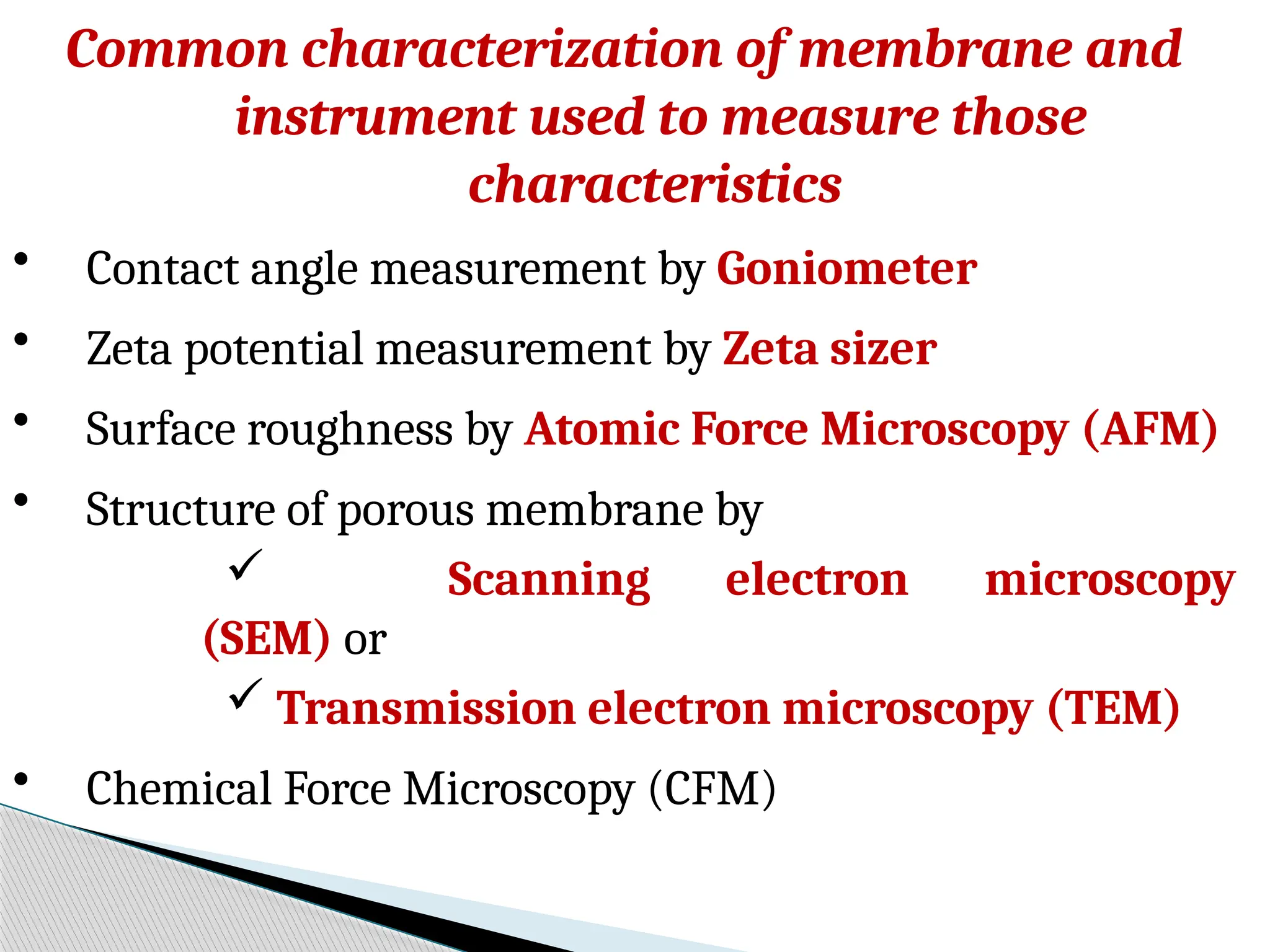
Common characterization ofmembrane and
instrument used to measure those
characteristics
• Contact angle measurement by Goniometer
• Zeta potential measurement by Zeta sizer
• Surface roughness by Atomic Force Microscopy (AFM)
• Structure of porous membrane by
Scanning electron microscopy
(SEM) or
Transmission electron microscopy (TEM)
• Chemical Force Microscopy (CFM)
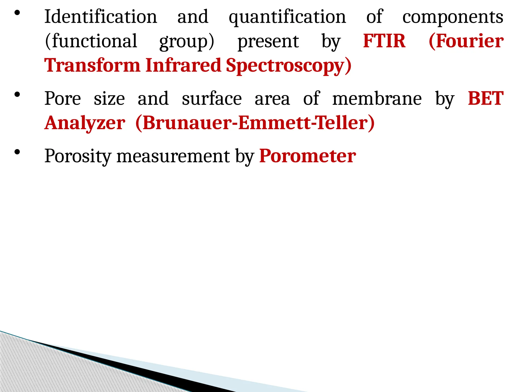
96.
• Identification andquantification of components
(functional group) present by FTIR (Fourier
Transform Infrared Spectroscopy)
• Pore size and surface area of membrane by BET
Analyzer (Brunauer-Emmett-Teller)
• Porosity measurement by Porometer
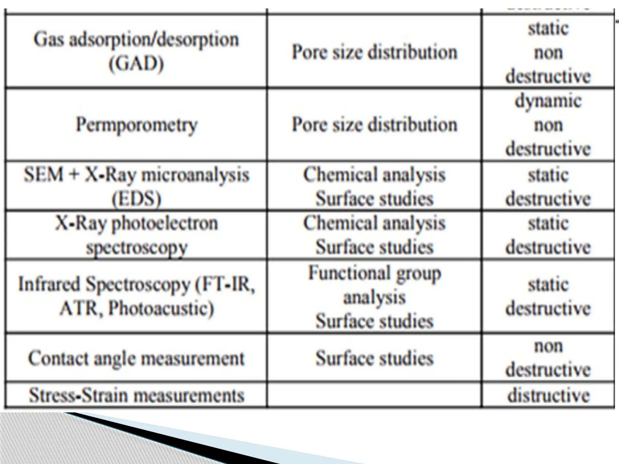
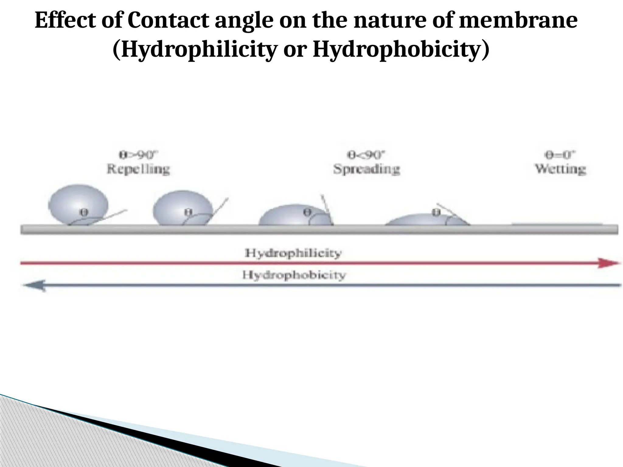
99.
Effect of Contactangle on the nature of membrane
(Hydrophilicity or Hydrophobicity)
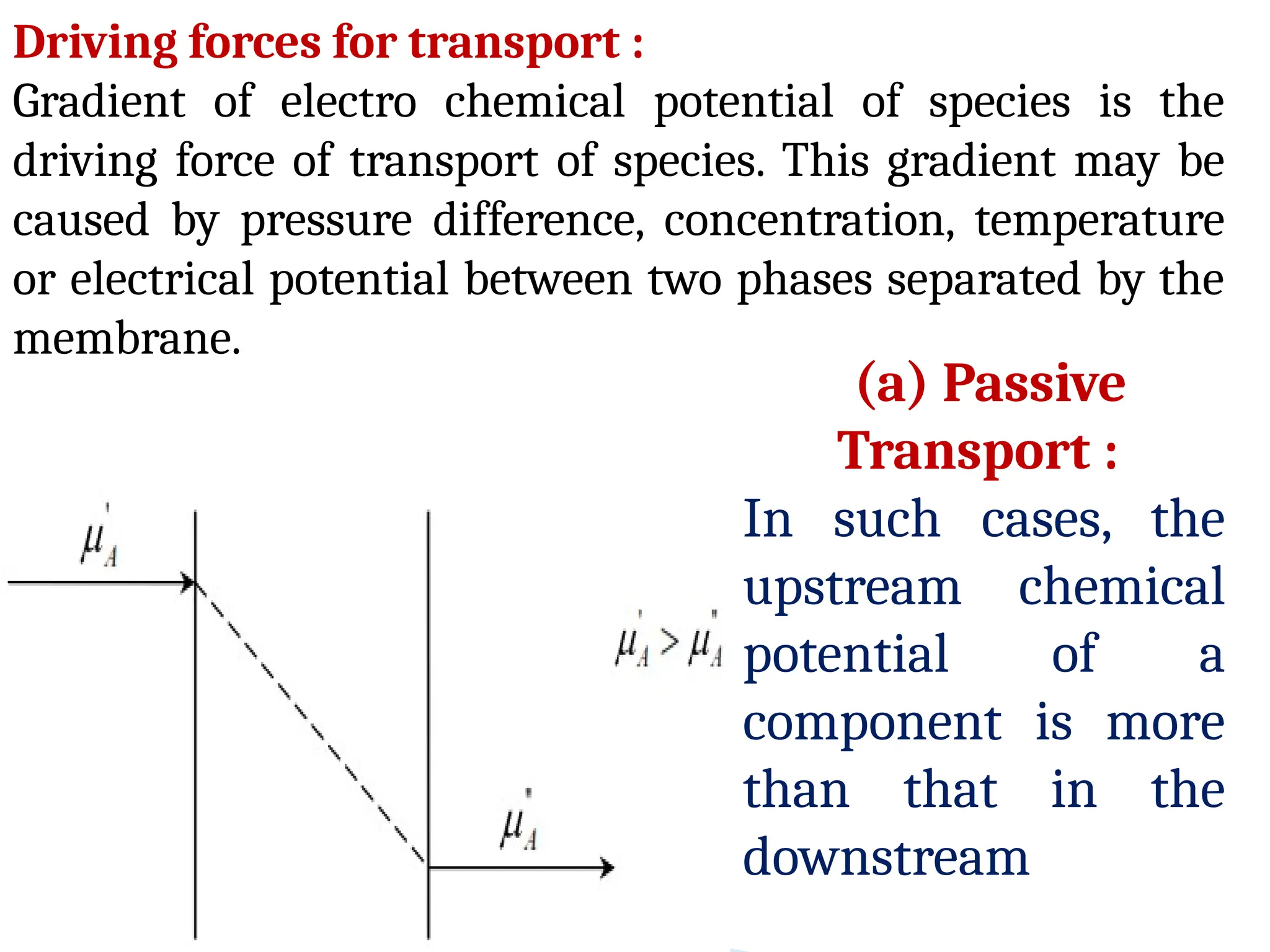
Driving forces fortransport :
Gradient of electro chemical potential of species is the
driving force of transport of species. This gradient may be
caused by pressure difference, concentration, temperature
or electrical potential between two phases separated by the
membrane.
(a) Passive
Transport :
In such cases, the
upstream chemical
potential of a
component is more
than that in the
downstream
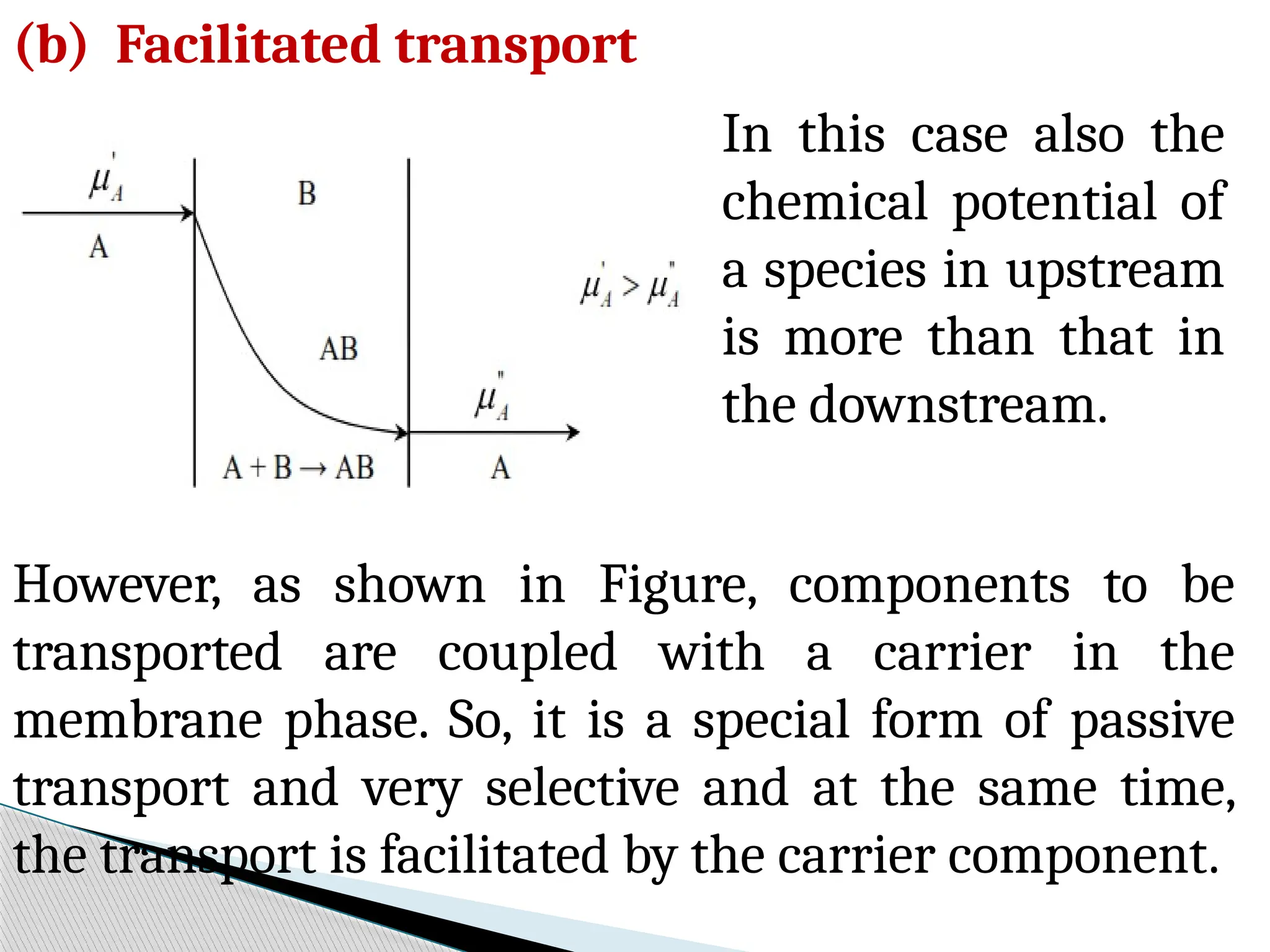
102.
In this casealso the
chemical potential of
a species in upstream
is more than that in
the downstream.
(b) Facilitated transport
However, as shown in Figure, components to be
transported are coupled with a carrier in the
membrane phase. So, it is a special form of passive
transport and very selective and at the same time,
the transport is facilitated by the carrier component.
103.
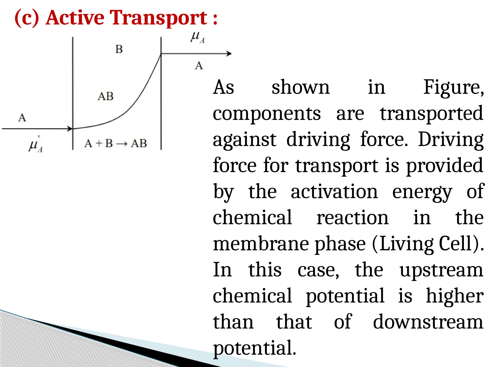
(c) Active Transport:
As shown in Figure,
components are transported
against driving force. Driving
force for transport is provided
by the activation energy of
chemical reaction in the
membrane phase (Living Cell).
In this case, the upstream
chemical potential is higher
than that of downstream
potential.


![Lecture_16-Membrane_Separation process[1].pdf](https://cdn.slidesharecdn.com/ss_thumbnails/lecture16-membraneseparation1-240711153552-a46ac636-thumbnail.jpg?width=640&height=640&fit=bounds)


