Download to read offline

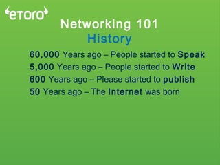
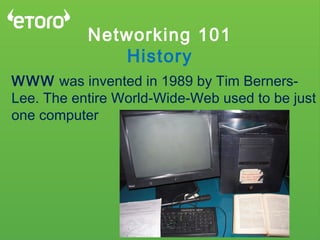

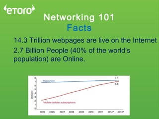


This document provides an overview of computer networking concepts including: - A brief history of networking from 60,000 years ago to the invention of the World Wide Web in 1989. - Key facts about internet growth from 38 million broadband users in 1999 to over 2.7 billion people online today. - An explanation of how networking standards like TCP/IP and the OSI model were developed to enable communication between different computer systems. - A high-level overview of the seven layers of the OSI model and examples of technologies that operate at each layer. - Descriptions of common networking concepts like DNS, NAT, VLANs, and wireless networking.