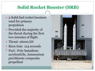
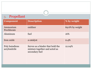
GOKUL LAKSHMANAN
M.TEC H TH ER MA L A N D FLU ID EN GIN EER IN G
NASA’S SPACE LAUNCH SYSTEM:
AHEAVY-LIFT PLATFORM FOR ENTIRELY NEW
MISSIONS
Contents
 Solid Rocket Booster (SRB)
 SRB testing
 Components
 Operation sequence
 Range safety system
Solid Rocket Booster (SRB)
 2 Solid fuel rocket boosters
used for primary
propulsion
 Provided the majority of
the thrust during the first
two minutes of flight.
 Thrust :16000 kN
 Burn time 124 seconds
 Fuel : Poly-butadiene
acrylonitrile, Ammonium
perchlorate composite
propellant
 Burns up to an altitude of about 45 km
 Non - reusable
 Material : Aluminum / Steel and composite materials
 Operation : Igniting, Steering and Jettison of the
boosters
SRB Testing
Components
1. Hold-down posts
 Each solid rocket booster has four hold-down posts
 Hold-down bolts hold the SRB and launcher
platform together
 Hold down nuts contains NASA Standard
Detonators(NSD) which were ignited at SRB ignition
commands
 NSD ignite and splits the nut into two or more parts
 Hold-down bolt travels downward
 Bolt were stopped by the stud deceleration stand
which contains sand
 The SRB bolt is 710 mm long and 89 mm in diameter
2. Electrical power distribution
 DC power is distributed to each SRB via SRB buses
labeled A, B and C
 SLS main DC buses A, B and C supplies power to
corresponding SRB buses A, B and C.
 In addition, SLS main DC bus C supplied backup power
to SRB buses A and B, and SLS bus B supplied backup
power to SRB bus C.
 This electrical power distribution arrangement allowed
all SRB buses to remain powered in the event one SLS
main bus failed
 The nominal operating voltage was 28±4 volts DC.
3. Hydraulic power units
 Two self-contained, independent Hydraulic Power
Units (HPUs) on each SRB
 HPU consisted of an auxiliary power unit, hydraulic
pump, hydraulic reservoir and hydraulic fluid
manifold
 The APUs were fueled by hydrazine
 Generates mechanical shaft power to drive a
hydraulic pump that produced hydraulic pressure for
the SRB hydraulic system.
 Hydrazine is feed into a gas generator. The gas
generator decompose the hydrazine into hot, high-
pressure gas
 A turbine converted this into mechanical power,
driving a gearbox.
 The gearbox drive the fuel pump, its own lubrication
pump, and the HPU hydraulic pump.
 The waste gas from gas generator now cooler and at
low pressure, was passed back over the gas generator
housing to cool it before being dumped overboard.
 Each HPU is connected to servo actuators
 The hydraulic pump speed was 3600 rpm and
supplied hydraulic pressure of 21.03 ± 0.34 Mpa
 Hydraulic pressure is used to drive Thrust vector
controller
 The hydraulic system is operated from T minus 28
seconds until SRB separation from the SLS
4. Thrust vector control
 Each SRB had two hydraulic servo actuators, to
move the nozzle up/down and side-to-side.
 This provided thrust vectoring to help control the
vehicle in all three axes (roll, pitch, and yaw).
 Each SRB servo actuator consist of four independent,
servo valves that receive signals from the drivers.
 Each servo valve control one actuator ram and thus
nozzle to control the direction of thrust.
5. Propellant
Component Description % by weight
Ammonium
Perchlorate
oxidizer 69.6% by weight
Aluminum fuel 16%
Iron oxide a catalyst 0.4%
Poly butadiene
acrylonitrile
Serves as a binder that hold the
mixture together and acted as
secondary fuel
12.04%
OPERATION SEQUENCE
1. Ignition
 Ignition can occur only when a manual lock pin from
each SRB has been removed.
 The ground crew removes the pin during prelaunch
activities at T minus five minutes
 The solid rocket booster ignition commands are
issued when four cryogenic engines are at or above
90% rated thrust
 The solid rocket ignition commands were sent by the
on-board computers
 The fire commands
cause the NSDs on the
SRB to fire.
 This ignites a pyro
booster charge.
 The booster charge
ignites the propellant in
the SRB which fires down
the entire vertical length
 This ignites the solid
rocket propellant along
its entire surface area
instantaneously.
 At t minus zero, the two
SRBs are ignited, under
command of the four
onboard computers
 Separation of the four
explosive bolts on each SRB
is initiated
 The two umbilical cords are
retracted
 The onboard master timing
unit and event timer are
started
 The four cryogenic engines
are at 100% and the ground
launch sequence is
terminated and liftoff occurs
2. Separation
 The SRBs are jettisoned from SLS at altitude, about
45 km.
 SRB separation is initiated when chamber pressure
of both SRBs is less than or equal to 340 kPa.
 The SRBs separate from the SLS within 30
milliseconds of the firing command.
 The forward attachment point consists a nut-bolt
system. It contains one NSD pressure cartridge.
 The aft attachment points consist of three separate
struts: upper, diagonal and lower. Each strut
contains one bolt with an NSD pressure cartridge at
each end.
 Detonating the NSD via electrical system separates
the SRB’s
3. Descent and Recovery
 The SRBs are jettisoned
from the SLS at 2 minutes
and an altitude of about 45
km.
 After continuing to rise to
about 67 km the SRBs begin
to fall back to earth
 Once back in the
atmosphere are slowed by a
parachute system to prevent
damage on ocean impact
 Nose cap separation occurs at a nominal altitude of
5km, about 218 seconds after SRB separation.
 This triggers the parachute to open and SRB falls to
ocean
 A command is sent from the SNS to the SRB just
before separation to apply battery power to the
recovery logic network
 SRB is recovered by US Navy
SRB Flash Down into Ocean
Range safety system
 A range safety system provides destruction of rocket or
its parts with on-board explosives by remote command if
the rocket is out of control
 This limits the danger to people on the ground from
crashing pieces, explosions, fire, poisonous substances,
etc.
 Two RSSs one in each SRB.
 Capable of receiving command messages transmitted
from the ground station.
 The RSS was used only when the shuttle vehicle violates
launch trajectory
 Two confined detonating fuse manifolds (CDF)
 The NSDs provide the spark to ignite the CDF which
results in booster destruction.
 The safe and arm device provides mechanical
isolation between the NSDs and the CDF before
launch and during the SRB separation sequence.
NASA SLS Solid Rocket Booster - Complete Explanation

NASA SLS Solid Rocket Booster - Complete Explanation

  • 1.
    GOKUL LAKSHMANAN M.TEC HTH ER MA L A N D FLU ID EN GIN EER IN G NASA’S SPACE LAUNCH SYSTEM: AHEAVY-LIFT PLATFORM FOR ENTIRELY NEW MISSIONS
  • 2.
    Contents  Solid RocketBooster (SRB)  SRB testing  Components  Operation sequence  Range safety system
  • 3.
    Solid Rocket Booster(SRB)  2 Solid fuel rocket boosters used for primary propulsion  Provided the majority of the thrust during the first two minutes of flight.  Thrust :16000 kN  Burn time 124 seconds  Fuel : Poly-butadiene acrylonitrile, Ammonium perchlorate composite propellant
  • 4.
     Burns upto an altitude of about 45 km  Non - reusable  Material : Aluminum / Steel and composite materials  Operation : Igniting, Steering and Jettison of the boosters
  • 6.
  • 7.
    Components 1. Hold-down posts Each solid rocket booster has four hold-down posts  Hold-down bolts hold the SRB and launcher platform together  Hold down nuts contains NASA Standard Detonators(NSD) which were ignited at SRB ignition commands  NSD ignite and splits the nut into two or more parts  Hold-down bolt travels downward  Bolt were stopped by the stud deceleration stand which contains sand  The SRB bolt is 710 mm long and 89 mm in diameter
  • 9.
    2. Electrical powerdistribution  DC power is distributed to each SRB via SRB buses labeled A, B and C  SLS main DC buses A, B and C supplies power to corresponding SRB buses A, B and C.  In addition, SLS main DC bus C supplied backup power to SRB buses A and B, and SLS bus B supplied backup power to SRB bus C.  This electrical power distribution arrangement allowed all SRB buses to remain powered in the event one SLS main bus failed  The nominal operating voltage was 28±4 volts DC.
  • 11.
    3. Hydraulic powerunits  Two self-contained, independent Hydraulic Power Units (HPUs) on each SRB  HPU consisted of an auxiliary power unit, hydraulic pump, hydraulic reservoir and hydraulic fluid manifold  The APUs were fueled by hydrazine  Generates mechanical shaft power to drive a hydraulic pump that produced hydraulic pressure for the SRB hydraulic system.
  • 12.
     Hydrazine isfeed into a gas generator. The gas generator decompose the hydrazine into hot, high- pressure gas  A turbine converted this into mechanical power, driving a gearbox.  The gearbox drive the fuel pump, its own lubrication pump, and the HPU hydraulic pump.  The waste gas from gas generator now cooler and at low pressure, was passed back over the gas generator housing to cool it before being dumped overboard.
  • 13.
     Each HPUis connected to servo actuators  The hydraulic pump speed was 3600 rpm and supplied hydraulic pressure of 21.03 ± 0.34 Mpa  Hydraulic pressure is used to drive Thrust vector controller  The hydraulic system is operated from T minus 28 seconds until SRB separation from the SLS
  • 15.
    4. Thrust vectorcontrol  Each SRB had two hydraulic servo actuators, to move the nozzle up/down and side-to-side.  This provided thrust vectoring to help control the vehicle in all three axes (roll, pitch, and yaw).  Each SRB servo actuator consist of four independent, servo valves that receive signals from the drivers.  Each servo valve control one actuator ram and thus nozzle to control the direction of thrust.
  • 17.
    5. Propellant Component Description% by weight Ammonium Perchlorate oxidizer 69.6% by weight Aluminum fuel 16% Iron oxide a catalyst 0.4% Poly butadiene acrylonitrile Serves as a binder that hold the mixture together and acted as secondary fuel 12.04%
  • 18.
    OPERATION SEQUENCE 1. Ignition Ignition can occur only when a manual lock pin from each SRB has been removed.  The ground crew removes the pin during prelaunch activities at T minus five minutes  The solid rocket booster ignition commands are issued when four cryogenic engines are at or above 90% rated thrust  The solid rocket ignition commands were sent by the on-board computers
  • 19.
     The firecommands cause the NSDs on the SRB to fire.  This ignites a pyro booster charge.  The booster charge ignites the propellant in the SRB which fires down the entire vertical length
  • 20.
     This ignitesthe solid rocket propellant along its entire surface area instantaneously.  At t minus zero, the two SRBs are ignited, under command of the four onboard computers
  • 21.
     Separation ofthe four explosive bolts on each SRB is initiated  The two umbilical cords are retracted  The onboard master timing unit and event timer are started  The four cryogenic engines are at 100% and the ground launch sequence is terminated and liftoff occurs
  • 22.
    2. Separation  TheSRBs are jettisoned from SLS at altitude, about 45 km.  SRB separation is initiated when chamber pressure of both SRBs is less than or equal to 340 kPa.  The SRBs separate from the SLS within 30 milliseconds of the firing command.
  • 23.
     The forwardattachment point consists a nut-bolt system. It contains one NSD pressure cartridge.  The aft attachment points consist of three separate struts: upper, diagonal and lower. Each strut contains one bolt with an NSD pressure cartridge at each end.  Detonating the NSD via electrical system separates the SRB’s
  • 24.
    3. Descent andRecovery  The SRBs are jettisoned from the SLS at 2 minutes and an altitude of about 45 km.  After continuing to rise to about 67 km the SRBs begin to fall back to earth  Once back in the atmosphere are slowed by a parachute system to prevent damage on ocean impact
  • 25.
     Nose capseparation occurs at a nominal altitude of 5km, about 218 seconds after SRB separation.  This triggers the parachute to open and SRB falls to ocean  A command is sent from the SNS to the SRB just before separation to apply battery power to the recovery logic network  SRB is recovered by US Navy
  • 26.
    SRB Flash Downinto Ocean
  • 27.
    Range safety system A range safety system provides destruction of rocket or its parts with on-board explosives by remote command if the rocket is out of control  This limits the danger to people on the ground from crashing pieces, explosions, fire, poisonous substances, etc.  Two RSSs one in each SRB.  Capable of receiving command messages transmitted from the ground station.  The RSS was used only when the shuttle vehicle violates launch trajectory
  • 28.
     Two confineddetonating fuse manifolds (CDF)  The NSDs provide the spark to ignite the CDF which results in booster destruction.  The safe and arm device provides mechanical isolation between the NSDs and the CDF before launch and during the SRB separation sequence.

Editor's Notes

  • #20 Typical pyrotechnic formulations consist either of flammable materials such as nitrocellulose and/or black powder