
Recommended
More Related Content
What's hot
What's hot (20)
Viewers also liked
Viewers also liked (14)
Similar to SRB Ignition and Liftoff in 40 Characters
Similar to SRB Ignition and Liftoff in 40 Characters (20)
More from isrokids
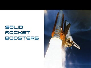
SRB Ignition and Liftoff in 40 Characters
- 2. Overview Two solid rocket boosters provide the main thrust to lift the Space Shuttle off the pad. They are the largest solid-propellant motors ever flown, the first designed for reuse.
- 3. Solid Rocket Booster Segment Arrival
- 5. Stacking SRB
- 6. SRB Diagram
- 7. SRB Transport to Pad Eight attach posts, four on the aft skirt of each SRB, support and hold the Space Shuttle on the Mobile Launcher Platform. These posts fit on counterpart posts located in the Platform's two solid rocket booster support wells. The space vehicle disconnects from the Platform by explosive nuts that release the giant studs linking the solid rocket attach posts with the Platform support posts.
- 8. Hold-Down Posts Each SRB has four hold-down posts securing it to the launch platform. At the T -0:00:0 mark, the SRBs are ignited and the eight giant hold-down posts on the SRBs are released. At that instant, liftoff occurs.
- 10. Hydraulic Power Units Each SRB has two self-contained independent hydraulic power units. The purpose of the SRB Hydraulic system is to supply the required hydraulic flow and pressure to extend and retract the actuator piston. The end of the piston is attached to the nozzle of the solid rocket motor to provide thrust vectoring during the mission. This system is called Thrust Vector Control (TVC), and it provides 80% of steering for the integrated vehicle during ascent. A similar system vectors the main engine nozzles, providing the other 20% of the steering control.
- 12. SRB Rate Gyro Assemblies Each SRB has two Rate Gyro Assemblies (RGAs) that provide attitude data to the orbiter computers during ascent.
- 16. Terminology/Acronyms SRB - Solid Rocket Booster RGA - Rate Gyro Assemblies TVC - Thrust Vector Control RSS - Range Safety System RPSF - Rotation Processing and Surge Facility CVSA - Check Valve Filter Assembly APU - Auxiliary Power Unit
- 17. STS 102 Booster Recovery Slideshow (Slides will advance every 3 seconds) PHOTOS BY RICK TUBRIDY
- 18. STS 102
- 19. STS 102 STS 102
- 20. STS 102 STS 102
- 21. STS 102
- 22. STS 102
- 23. STS 102
- 24. STS 102
- 25. STS 102
- 26. STS 102
- 27. STS 102
- 28. STS 102
- 29. STS 102
- 30. STS 102
- 31. STS 102
- 32. STS 102
- 33. STS 102
- 34. STS 102
- 35. STS 102
- 36. STS 102
- 37. STS 102
- 38. STS 102
Editor's Notes
- Solid Rocket Boosters Presentation
- The two SRBs provide the main thrust to lift the Space Shuttle off the pad and up to an altitude of about 150,000 feet, or 24 nautical miles (28 statute miles). In addition, the two SRBs carry the entire weight of the external tank and orbiter and transmit the weight load through their structure to the mobile launcher platform. Each booster has a thrust (sea level) of approximately 3,300,000 pounds at launch. They are ignited after the three space shuttle main engines' thrust level is verified. The two SRBs provide 71.4 percent of the thrust at lift off and during first-stage ascent. Seventy-five seconds after SRB separation, SRB apogee occurs at an altitude of approximately 220,000 feet, or 35 nautical miles (41 statute miles). SRB impact occurs in the ocean approximately 122 nautical miles (141 statute miles) downrange. The SRBs are the largest solid-propellant motors ever flown and the first designed for reuse. Each is 149.16 feet long and 12.17 feet in diameter. Each SRB weighs approximately 1,300,000 pounds at launch. The propellant for each solid rocket motor weighs approximately 1,100,000 pounds. The inert weight of each SRB is approximately 192,000 pounds. Primary elements of each booster are the motor (including case, propellant, igniter, and nozzle), structure, separation systems, operational flight instrumentation, recovery avionics, pyrotechnics, deceleration system, thrust vector control system, and range safety destruct system. Each booster is attached to the external tank at the SRB’s aft frame by two lateral sway braces and a diagonal attachment. The forward end of each SRB is attached to the external tank at the forward end of the SRB's forward skirt. On the launch pad, each booster also is attached to the mobile launcher platform at the aft skirt by four bolts and nuts that are severed by small explosives at lift off. During the downtime following the Challenger accident, detailed structural analyses were performed on critical structural elements of the SRB. Analyses were primarily focused in areas where anomalies had been noted during post-flight inspection of recovered hardware. One of the areas was the attach ring where the SRBs are connected to the external tank. Areas of distress were noted in some of the fasteners where the ring attaches to the SRB motor case. This situation was attributed to the high loads encountered during water impact. To correct the situation and ensure higher strength margins during ascent, the attach ring was redesigned to encircle the motor case completely (360 degrees). Previously, the attach ring formed a C and encircled the motor case 270 degrees. Additionally, special structural tests were performed on the aft skirt. During this test program, an anomaly occurred in a critical weld between the hold-down post and skin of the skirt. A redesign was implemented to add reinforcement brackets and fittings in the aft ring of the skirt. These two modifications added approximately 450 pounds to the weight of each SRB. The propellant mixture in each SRB motor consists of an ammonium perchlorate (oxidizer, 69.6 percent by weight), aluminum (fuel, 16 percent), iron oxide (a catalyst, 0.4 percent), a polymer (a binder that holds the mixture together, 12.04 percent), and an epoxy curing agent (1.96 percent). The propellant is an 11-point star-shaped perforation in the forward motor segment and a double-truncated-cone perforation in each of the aft segments and aft closure. This configuration provides high thrust at ignition and then reduces the thrust by approximately a third 50 seconds after lift-off to prevent overstressing the vehicle during maximum dynamic pressure. The SRBs are used as matched pairs, and each is made up of four solid rocket motor segments. The pairs are matched by loading each of the four motor segments in pairs from the same batches of propellant ingredients to minimize any thrust imbalance. The segmented-casing design assures maximum flexibility in fabrication and ease of transportation and handling. Each segment is shipped to the launch site on a heavy-duty rail car with a specially built cover. The nozzle expansion ratio of each booster beginning with the STS-8 mission is 7-to-79. The nozzle is gimbaled for thrust vector (direction) control. Each SRB has its own redundant auxiliary power units and hydraulic pumps. The all-axis gimbaling capability is 8 degrees. Each nozzle has a carbon cloth liner that erodes and chars during firing. The nozzle is a convergent- divergent, movable design in which an aft pivot- point flexible bearing is the gimbal mechanism. The cone-shaped aft skirt reacts the aft loads between the SRB and the mobile launcher platform. The four aft separation motors are mounted on the skirt. The aft section contains avionics, a thrust vector control system that consists of two auxiliary power units and hydraulic pumps, hydraulic systems, and a nozzle extension jettison system. The forward section of each booster contains avionics, a sequencer, forward separation motors, a nose cone separation system, drogue and main parachutes, a recovery beacon, a recovery light, a parachute camera on selected flights, and a range safety system. Each SRB has two integrated electronic assemblies, one forward and one aft. After burnout, the forward assembly initiates the release of the nose cap and frustum and turns on the recovery aids. The aft assembly, mounted in the external tank/SRB attach ring, connects with the forward assembly and the orbiter avionics systems for SRB ignition commands and nozzle thrust vector control. Each integrated electronic assembly has a multiplexer/ demultiplexer that sends or receives more than one message, signal or unit of information on a single communication channel. Eight booster separation motors (four in the nose frustum and four in the aft skirt) of each SRB thrust for 1.02 seconds at SRB separation from the external tank. Each solid rocket separation motor is 31.1 inches in length and 12.8 inches in diameter. Location aids are provided for each SRB, frustum/ drogue chutes, and main parachutes. These include a transmitter, antenna, strobe/ converter, battery, and salt water switch electronics. The location aids are designed for a minimum operating life of 72 hours and when refurbished are considered usable up to 20 times. The flashing light is an exception. It has an operating life of 280 hours. The battery is used only once. The SRB nose caps and nozzle extensions are not recovered. The recovery crew retrieves the SRBs, frustum/ drogue chutes, and main parachutes. The nozzles are plugged, the solid rocket motors are dewatered, and the SRBs are towed back to the launch site. Each booster is removed from the water, and its components are disassembled and washed with fresh and deionized water to limit salt water corrosion. The motor segments, igniter, and nozzle are shipped back to Thiokol for refurbishment. Each SRB incorporates a range safety system that includes a battery power source, receiver/decoder, antennas, and ordnance.
- The solid rocket booster segments arrive at KSC via rail from Brigham City, UT, and are offloaded at that Rotation Processing and Surge Facility (RPSF) just north of the Vehicle Assembly Building (VAB).
- With a Security escort, the first Solid Rocket Booster (SRB) aft skirt for mission STS-114 nears the Vehicle Assembly Building on its transfer to the Rotation Processing and Surge Facility for stacking. At the facility, an aft motor segment and an external tank attach ring will be installed. The stack will then be moved to the Vehicle Assembly Building for further build-up.
- These are two videos that help explain the stacking process. Both videos should open in a new window and require Real Player.
- Can you imagine being responsible for stacking all of this? Phew!
- Eight attach posts, four on the aft skirt of each SRB, support and hold the Space Shuttle on the Mobile Launcher Platform. These posts fit on counterpart posts located in the Platform's two solid rocket booster support wells. The space vehicle disconnects from the Platform by explosive nuts that release the giant studs linking the solid rocket attach posts with the Platform support posts.
- Each SRB has four hold-down posts securing it to the launch platform. At the T -0:00:0 mark, the SRBs are ignited and the eight giant hold-down posts on the SRBs are released. At that instant, liftoff occurs.
- The final 31 seconds of countdown are the busiest, as the Shuttle's on-board computers take over the count, and every system on the vehicle operates on internal power. The Shuttle's three main engines (SSMEs) are sequentially started at approximately the T -7 second mark. When the engine controllers indicate that they are all running normally, the twin solid rocket boosters (SRBs) are ignited at the T -0 mark. A sequence of events occurs within a few seconds before launch, leading up to SRB ignition and liftoff.
- Each SRB has two self-contained independent hydraulic power units. The purpose of the SRB Hydraulic system is to supply the required hydraulic flow and pressure to extend and retract the actuator piston. The end of the piston is attached to the nozzle of the solid rocket motor to provide thrust vectoring during the mission. This system is called Thrust Vector Control (TVC), and it provides 80% of steering for the integrated vehicle during ascent. A similar system vectors the main engine nozzles, providing the other 20% of the steering control.
- Each SRB has two hydraulic gimbal servoactuators: one for rock and one for tilt. The servoactuators provide the force and control to gimbal the nozzle for thrust vector control.
- Each SRB contains two RGAs, with each RGA containing one pitch and one yaw gyro. These provide an output proportional to angular rates about the pitch and yaw axes to the orbiter computers and guidance, navigation, and control system during first-stage ascent flight in conjunction with the orbiter roll rate gyros until SRB separation. At SRB separation, a switchover is made from the SRB RGAs to the orbiter RGAs. The SRB RGA rates pass through the orbiter flight aft multiplexers/demultiplexers to the orbiter GPCs. The RGA rates are then mid-value-selected in redundancy management to provide SRB pitch and yaw rates to the user software. The RGAs are designed for 20 missions.
- SRB separation is initiated when the three solid rocket motor chamber pressure transducers are processed in the redundancy management middle value select and the head-end chamber pressure of both SRBs is less than or equal to 50 psi. A backup cue is the time elapsed from booster ignition. The separation sequence is initiated, commanding the thrust vector control actuators to the null position and putting the main propulsion system into a second-stage configuration (0.8 second from sequence initialization), which ensures the thrust of each SRB is less than 100,000 pounds. Orbiter yaw attitude is held for four seconds, and SRB thrust drops to less than 60,000 pounds. The SRBs separate from the external tank within 30 milliseconds of the ordnance firing command. The forward attachment point consists of a ball (SRB) and socket (ET) held together by one bolt. The bolt contains one NSD pressure cartridge at each end. The forward attachment point also carries the range safety system cross-strap wiring connecting each SRB RSS and the ET RSS with each other. The aft attachment points consist of three separate struts: upper, diagonal, and lower. Each strut contains one bolt with an NSD pressure cartridge at each end. The upper strut also carries the umbilical interface between its SRB and the external tank and on to the orbiter. There are four booster separation motors on each end of each SRB. The BSMs separate the SRBs from the external tank. The solid rocket motors in each cluster of four are ignited by firing redundant NSD pressure cartridges into redundant confined detonating fuse manifolds. The separation commands issued from the orbiter by the SRB separation sequence initiate the redundant NSD pressure cartridge in each bolt and ignite the BSMs to effect a clean separation.
- The Shuttle vehicle has three RSSs. One is located in each SRB and one in the external tank. Any one or all three are capable of receiving two command messages (arm and fire) transmitted from the ground station. The RSS is used only when the Shuttle vehicle violates a launch trajectory red line. Maximum dynamic pressure is reached early in the ascent, nominally approximately 60 seconds after liftoff. Approximately 1 minute later (2 minutes into the ascent phase), the two SRB have consumed their propellant and are jettisoned from the external tank. This is triggered by a separation signal from the orbiter. An RSS consists of two antenna couplers, command receivers/ decoders, a dual distributor, a safe and arm device with two NSDs, two confined detonating fuse manifolds, seven CDF assemblies, and one linear-shaped charge. The antenna couplers provide the proper impedance for radio frequency and ground support equipment commands. The command receivers are tuned to RSS command frequencies and provide the input signal to the distributors when an RSS command is sent. The command decoders use a code plug to prevent any command signal other than the proper command signal from getting into the distributors. The distributors contain the logic to supply valid destruct commands to the RSS pyrotechnics. The NSDs provide the spark to ignite the CDF, which in turn ignites the LSC for shuttle vehicle destruction. The safe and arm device provides mechanical isolation between the NSDs and the CDF before launch and during the SRB separation sequence. The first message, called arm, allows the onboard logic to enable a destruct and illuminates a light on the flight deck display and control panel at the commander and pilot station. The second message transmitted is the fire command. The SRB distributors in the SRBs and the ET are cross-strapped together. Thus, if one SRB received an arm or destruct signal, the signal would also be sent to the other SRB and the ET. Electrical power from the RSS battery in each SRB is routed to RSS system A. The recovery battery in each SRB is used to power RSS system B as well as the recovery system in the SRB. The SRB RSS is powered down during the separation sequence, and the SRB recovery system is powered up. Electrical power for the ET RSS system A and system B is independently supplied by two RSS batteries on the ET.
- Exactly 295 seconds after they separate from the vehicle, both SRBs fall into the Atlantic Ocean, where they are recovered for reuse.
- Here Is a review of the SRB and some important acronyms you learned about today.
- Descent and Recovery The recovery sequence begins with the operation of the high-altitude baroswitch, which triggers the functioning of the pyrotechnic nose cap thrusters. This ejects the nose cap, which deploys the pilot parachute. This occurs at 15,704 feet altitude 225 seconds after separation. The 11.5-foot-diameter conical ribbon pilot parachute provides the force to pull the lanyard activating the zero-second cutter, which cuts the loop securing the drogue retention straps. This allows the pilot chute to pull the drogue pack from the SRB, causing the drogue suspension lines to deploy from their stored position. At full extension of the 12 95-foot suspension lines, the drogue deployment bag is stripped away from the canopy, and the 54-foot-diameter conical ribbon drogue parachute inflates to its initial reefed condition. The drogue disreefs twice after specified time delays, and it reorients/stabilizes the SRB for main chute deployment. The drogue parachute can withstand a load of 270,000 pounds and weighs approximately 1,200 pounds. After the drogue chute has stabilized the vehicle in a tailfirst attitude, the frustum is separated from the forward skirt by a charge triggered by the low-altitude baroswitch at an altitude of 5,975 feet 248 seconds after separation. It is then pulled away from the SRB by the drogue chute. The main chutes' suspension lines are pulled out from deployment bags that remain in the frustum. At full extension of the lines, which are 204 feet long, the three main chutes are pulled from the deployment bags and inflate to their first reefed condition. The frustum and drogue parachute continue on a separate trajectory to splashdown. After specified time delays, the main chutes' reefing lines are cut, and the chutes inflate to their second reefed and full open configurations. The main chute cluster decelerates the SRB to terminal conditions. Each of the 136-foot-diameter, 20-degree conical ribbon parachutes can withstand a load of 180,000 pounds and weighs 2,180 pounds. The nozzle extension is severed by pyrotechnic charge either at apogee or 20 seconds after low baroswitch operation. Water impact occurs 295 seconds after separation at a velocity of 81 feet per second. The water impact range is approximately 140 miles off the eastern coast of Florida. Because the parachutes provide for a nozzle-first impact, air is trapped in the empty (burned out) motor casing, causing the booster to float with the forward end approximately 30 feet out of the water. The main chutes are released from the SRB at impact, using the parachute release nut ordnance system. Residual loads in the main chutes deploy the parachute attach fittings with the redundant flotation tethered to each fitting. The drogue and frustum; each main chute, with its flotation; and the SRB are buoyant. The SRB recovery aids are the radio beacon and flashing lights, which become operable at frustum separation. The radio transponder in each SRB has a range of 8.9 nautical miles (10.35 statute miles), and the flashing light has a nighttime range of 4.9 nautical miles (5.75 statute miles). Various parameters of SRB operation are monitored and displayed on the orbiter flight deck control and display panel and are transmitted to ground telemetry.