Download to read offline

![Munagunuri Suneel Babu Int. Journal of Engineering Research and Applications www.ijera.com
ISSN : 2248-9622, Vol. 4, Issue 11(Version - 4), November 2014, pp.88-90
www.ijera.com 90 | P a g e
Results comparison by material:
1. For the original 18 blade model the stress values of chromium steel (actual material) are more than the titanium alloy (G-5) so titanium alloy material is best for the original 18 blade model.
2. For the modified 16 blade model the stress values of chromium steel (actual material) are more than the titanium alloy (G-5) so titanium alloy material is best for the original 16 blade model.
3. For the modified 14 blade model the stress values of chromium steel (actual material) are more than the titanium alloy (G-5) so titanium alloy material is best for the original 14 blade model.
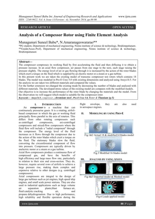
So we conclude that titanium alloy is best for rotor than chromium steel. Results comparison by the model: If we compare the model stress values the number of stress values are increased with number of blades increased so here our observation is that by reducing the blades the stress values are reduced for the efficiency of the rotor we have to use composite materials with this by the reduction of blades also efficiency increased. Future scope:
1. By changing the blade dimensions the efficiency may increased.
2. By using composite materials the efficiency may obtained.
3. By varying the thickness of the rotor the efficiency may increased.
REFERENCES:
[1.] S. Veeramachanemi, K. Krishna, L. Avinash, S.R. Puppola,M.B. Srinivas, "Novel architectures for high-speed and low-power 3-2, 4-2 and 5-2compressors," IEEE Proc. Oj VLSlD '07, pp. 324-329,2007.
[2.] C. H. Chang, J. Gu, M. Zhang, “Ultra low- voltage low power CMOS 4-2 and 5-2 compressors for fast arithmetic circuits” IEEE Transactions on Circuits and Systems I:Regular Papers, Volume 51, Issue 10, Oct. 2004 Page(s):1985 – 1997.
[3.] S. F. Hsiao, M. R. Jiang, and J. S. Yeh, “Design of high speed low-power 3-2 counter and 4-2 compressor for fast multipliers,” Electron. Lett, vol. 34, no. 4,pp. 341– 343,1998.
[4.] Numerical Simulation of an Axial Compressor with Non Axisymmetric Casing Treatment by N.Gourdain, M.Montagnac, J.F.Boussuge CERFACS, Computational Fluid Dynamics Team 31057 Toulouse, France [5.] Stall Inception in Axial Flow Compressors by I. J. Day [6.] Modeling of the double leakage and leakage spillage flows in axial flow compressors by Hui Du, Xianjun Yu, Baojie Liu
[7.] Design Methodology of a Two Stage Axial Compressor by Gaddam Srikanth Ȧ, S.Srinivas Prasad Ȧ, V.Mahesh Kumar Ȧ and B.Mounica Reddy
[8.] Numerical Investigation of Flow In An Axial Flow Compressor Cascade by T. Suthakar, Akash, National Institute of Technology, Tiruchirappalli
[9.] Effect of Variations in Aspect Ratio on Single Stage Axial Flow Compressor Using Numerical Analysis by Kumbhar Anil H., Aashish Agarwal, PG Student, Asso. Professor, Technocrats Institute of Technology, Bhopal, M.P, India. [10.] Frank Sieverding, Beat Ribi, Michael Casey, Michael Meyer (2004) Design of Industrial Axial Compressor Blade Sections for Optimal Range and Performance J. [11.] S M Yahya (2003) Fundamentals of Compressible flow, 81-224-1468-0, Tata Mc- Graw Hill. [12.] Philip G. Hill, Carl R. Peterson (2010), Mechanics and Thermodynamics of Propulsion, 0201146592, Addison-Wesley [13.] Jack D. Mattingly (1996), Elements of Gas turbine Propulsion, 0-07-912196-9, Tata Mc- Graw Hill.](https://image.slidesharecdn.com/n0411048890-141212222826-conversion-gate02/85/Analysis-of-a-Compessor-Rotor-using-Finite-Element-Analysis-3-320.jpg)

This document analyzes the stresses on an axial compressor rotor using finite element analysis. It summarizes the modeling, analysis, and results of analyzing an existing 18-blade rotor model using two materials (chromium steel and titanium alloy), as well as modified 16-blade and 14-blade models using the same materials. Von Mises stresses were lowest for the 14-blade titanium alloy model. The conclusion is that titanium alloy provides better performance than chromium steel, and reducing the number of blades from 18 to 14 further reduces stresses.