Download to read offline
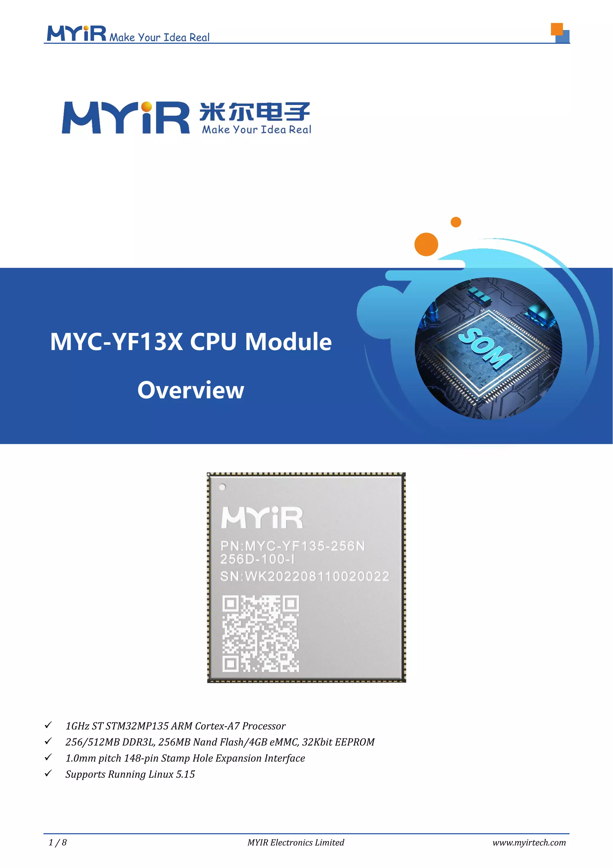
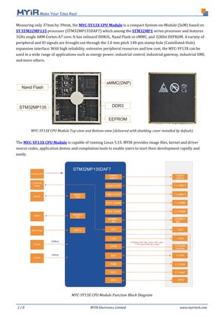
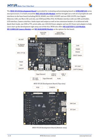
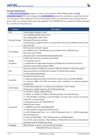
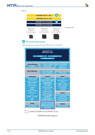
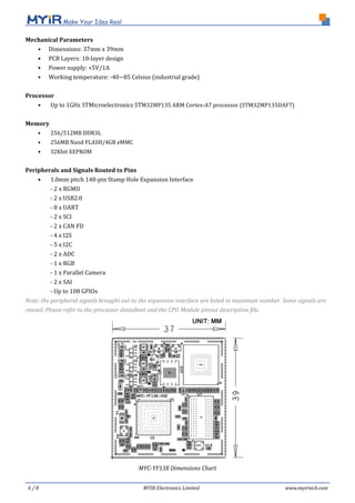
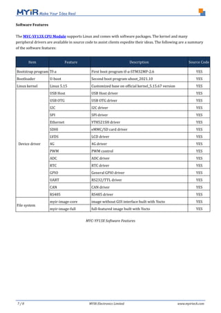

The myc-yf13x CPU module is a compact system-on-module featuring a 1GHz ARM Cortex-A7 processor with various memory options and extensive peripheral support, capable of running Linux 5.15. It enables a wide range of applications in industrial control and energy sectors, with a development board provided for easy prototyping. The product includes a comprehensive software package with source code for quick development and integration.


