Download to read offline
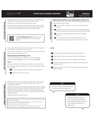

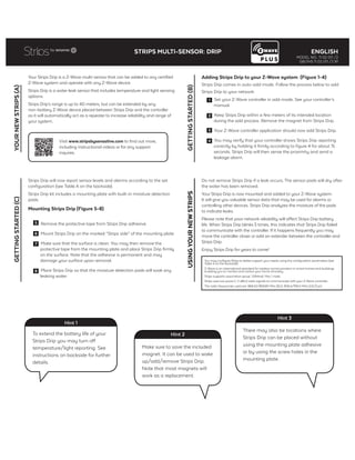
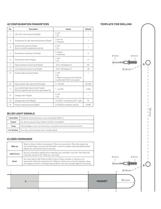

This document provides instructions for setting up and using the Strips Comfort multi-sensor device with a Z-Wave home automation system. It can measure temperature, light, and detect moisture. The sensor has a 40m range and comes with a mounting plate to attach it to walls or surfaces. To add it to a Z-Wave network, put the controller in add mode, wake up the sensor by removing its magnet, and verify it is reporting data correctly. The sensor's configuration and operation can be customized using its parameters in the Z-Wave controller.


