SlideShare a Scribd company logo
1 of 30
Download to read offline
SECTION-A
Chapter 7
• What are the design criteria of a machine tool structure? // Discuss the basic
design criteria of machine tool's structure.
Following factors should be considered while designing a machine tool structure:
• Decide materials for structure.
• Decide manufacturing process such as
a) Fabricated.
b) Cast
• Type of structure
a) Close
b) Open.
• Forces acting on structure which can cause bending and twisting.
• Take into account weight of structure, weight of workpiece etc.
• Nature of vibrations to be generated during working.
• The structure should have sufficient stiffness and strength.
• Define a machine tool.
A metal cutting machine tool is defined as a power-driven machine capable of
producing various shapes in metal by cutting away the surplus material. The
principle used in all the machine tools is one of the generating the surface required
by providing suitable relative motions between the cutting tool and the workpiece.
The metal removed by the cutting tool is called chip and will vary in size, shape and
form according to the type of material being cut, the cutting tool angle and the
position of the tool relative to the workpiece. The surface produced by the cutting
process is called machined surface.
• What are the basic features of a machine tool?
A machine tool is fundamentally an assembly of following basic elements (Fig. 7.3):
a) Bed, structure of frame.
b) Slides and slide ways.
c) Spindles and spindle bearing.
d) Power units.
e) Transmission linkage.
f) Work holding and tool holding elements.
• "High static stiffness reduces the dynamic stiffness"- Explain.
• What is the machine tool structures? How are the structures classified?
Machine tools parts such as beds, bases, columns, carriages, tables etc. are known
as machine tool structures.
Following are the essential requirements of structures for their satisfactory
performance.
→ The machine tool structures should be made of proper materials.
→ They should have high static and dynamic stiffness.
→ All-important mating surfaces of the structures should be machined with a
high degree of accuracy to provide the desired geometrical accuracy.
Depending upon the function structures are divided into following groups:
→ Beds and bases on which the various sub-assemblies are mounted.
→ Box type housings in which individual units are assembled such as spindle
head, speed box housing.
→ Parts used to support the cutting tool and work piece such as table,
carriage, tail stock and knee.
• Explain different types of stiffness.
Stiffness: The stiffness of a machine tool may be defined as the load per unit
deformation. A machine tool consists of a number of elements. These
elements experience deformation during operation of the machine tool and
therefore can be looked upon as elastic bodies (springs) with a certain
stiffness (spring constant) for a designer it is necessary to examine the
cumulative static and dynamic characteristics of the machine tool as well as
the corresponding characteristics of the individual elements of which the
machine tool is made.
The machine tool should be therefore checked for
1. Static stiffness, K = P(force)/Y(displacement): Static stiffness relates
the static loads applied to a machine element to the resulting
deflections.
2. Dynamic stiffness, Kd = Pd (dynamic force)/Yd(displacement): The
dynamic stiffness is the frequency dependent ratio between a
dynamic force and the resulting dynamic displacement.
Higher value of stiffness will give better accuracy during machining.
Dynamic rigidity behavior during vibrations under pulsating and inertia
forces. It is defined as the ratio of amplitude of vibratory force considered
harmonic to the vibratory displacement at a given frequency.
• Explain:
I) Stiffness and rigidity of machine tools,
Stiffness: The stiffness of a machine tool may be defined as the load per unit
deformation. Stiffness should be considered from the following points of view:
- Static stiffness against deformation under static loads.
- Dynamic rigidity behavior during vibrations under pulsating and inertia
forces. It is defined as the ratio of amplitude of vibratory force considered
harmonic to the vibratory displacement at a given frequency.
ii) Working motion and auxiliary motion.
In order to obtain the required shape on the workpiece it is necessary that the
cutting edge of the cutting tool should move in a particular manner with respect to
the workpiece. There are two types of motions in a machine tool.
a) Working motion
b) Auxiliary motion.
1. Working motion. In machine tools the working motions are powered by an
external source of energy such as electrical or hydraulic. The process of chip
removal is affected by the working motions of machine tool (formative motions)
which are transmitted either to the cutting tool, or to the work or to both
simultaneously.
Working motions of a machine tool are of the following types:
a) Primary cutting motion or Drive motion.
b) Feed motion.
Both primary cutting motion and feed motion is specified by speed or feed rate.
a) Primary cutting motion. It provides for cutting the chip from the blank at the
cutting speed equal to the velocity with which the chip leaves the work. The
most commonly used types of primary cutting motions are of two types:
i. Rotary primary cutting motion. Rotary motion may be transmitted
either to the work as in lathe group of machine tool or to the tool as
in grinding machine, drilling machine of milling machine. The cutting
speed (V) of a rotary cutting motion is given by
where D=Diameter of surface being
machined or of the rotating tool. (mm), N=R.P.M.of workpiece
of tool.
ii. Reciprocating primary cutting motion. This type of motion is used in
shapers, planers, slotters, power hacksaws and broaching machines.
This motion can be transmitted to the tool as in shaper and slotter or
to the work as in planer. The speed of return stroke should be kept
higher than that of working stroke in order to reduce the non-
productive time in machining. The average value of cutting speed(V) is
determined as follows: Where L= a
Length of working stroke in millimeter. N=Number of full strokes per
minute. One full stroke includes a working stroke and a return stroke.
b) Feed motion. The rate of feed or speed of the feed motion is substantially
less than the cutting speed. The feed motion enables the cutting process to
be extended to the whole surface to be machined on the work. Other
conditions being equal, the rate of feed determines the cross-sectional area
of the chip. The accuracy of the primary cutting motion depends mainly on
the design of the main spindle, while the accuracy of feed motion depends
upon the design of the bed.
2. Auxiliary Motion. The auxiliary motions do not take part in the process of
formation of the required surface but are none the less necessary to make the
working motions to fulfil their assigned function. The various types of auxiliary
motions in machine tools are as follows:
o Engaging and dis-engaging of working motions.
o Changing the speed of drive and feed motions.
o Clamping and un-clamping of workpiece.
The auxiliary motions may be carried out manually or they may be automated in
automatic machine tools.
• What is slideway?
A slide is a moving element providing a straight-line movement to a workpiece or a
tool holder at a controlled feed rate. A slide way gives accurate guiding constraints
to the slide and may contain some form of adjustments to eliminate play between
the two members as wear takes place.
• Make neat sketches of different forms of slideways? // Make neat sketches
of three different forms of slide and slide ways. Briefly explain them.
The common types of slide ways are as follows:
1. Flat slide way: Fig,7.11 shows flat slide ways. They possess a larger load
carrying capacity suitable for the larger type of machine They provide a large
area of contact; thus, wear is a minimum. It is easier to manufacture such
slide way and the geometric feature of these slide ways can be easily
checked. On the other hand, they have the following disadvantages
a) They require devices for adjusting the clearances
b) They have tendency to accumulate dirt.
c) They retain the lubricant comparatively poor
2. Vee and flat slide way: Vee ways are more difficult to manufacture than flat
ways but are capable of self-adjustment I.e., clearances are automatically
eliminated under the action of load. It has no tendency to accumulate dirt.
The drawback of the inverted vee type slide way is the lack of bearing surface
which results in rapid wear. For lathe bends both flat and inverted vee slide
ways commonly used. Fig.7.12 shows a combination of vee and flat ai ways.
It is simple to manufacture and is easily rescraped when wear has taken
place.
3. Dovetail slide way: They occupy small space. They are commonly used
where the cutting forces tend to produce upward movement of slide thus
causing vibrations. The gib strip can be adjusted so that the two elements of
the slide are a good sliding fit. This type of slide ways is used in center lathe
cross slide and compound slide. (Fig.7.13)
4. Roller slide way: In this system (Fig.7.14 rollers retained in a brass cage
interposed between the sliding members. This arrangement reduces the
friction between the two members of the slide because rolling friction is
substituted for sliding friction. Roller slide ways can be used to move heavy
load positively and accurately.
• Discuss the various factors to be considered for precession of machine tools.
The following factors affect the accuracy of finished components made on a
machine tool:
• Cutting tool geometry
• Strength and stiffness of machine tool
• Machining variables like:
a) cutting speed
b) feed
c) depth of cut
• Accuracy of bearings
• Vibrations in machine tool
• Nature of workpiece material
• Methods of chip removal
• Discuss the general requirements of machine tools.
Machine tool drives are used to transmit motion from power source to the
operative element of the machine tool. The general requirement for the machine
tool drives is that they should have provision for regulating the speed of travel of
the operative elements.
General Requirements of Machine Tool Design: The requirements of a machine
tool design are as follows:
▪ High productivity
▪ High accuracy of components manufactured
▪ Safety and convenience of controls
▪ Simplicity of design
▪ Low cost of manufacturing
▪ Low cost of operation
▪ Good appearance
• Why box section is more suitable for the beds of machine tools?
The box formation is convenient to produce, apertures in the walls
permitting the positioning and extraction of cores. It is quite commonly
used for lathe beds. Box type section has the highest torsional stiffness
and is best suited in terms of strength and stiffness. Also, box section
provides a better weight to strength ratio compared to a solid bed.
• Classify machine tools.
1. The principal type of machine tools on which cutting tools are used in the
modern workshop might be classified as follows:
a. Planer, shaper
b. Lathe
c. Milling machine
d. Drilling, tapping and reaming machines
e. Broach, saw
f. Grinders and polishers
g. Gear and thread cutting machines.
2. Degree of specialization. In respect of their degree of specialization the
machine tools can be referred to one of the following groups:
a. General purpose (Universal) machine tools. They are designed for
performing a great variety of machining operations on a wide range
of workpieces. They are employed chiefly in piece and small lot
production and for repair jobs.
b. Single purpose machine tools. They are designed for performing a
single definite machining operation. They may be readily set up for
machining different sized parts of the same type. Machine tools used
for machining crankpins of crankshafts, for turning the cam contours
on camshafts are included in this type.
c. Specialized machine tools. These machine tools are used to machine
a certain definite workpiece by making the necessary changes in their
construction. This group includes unit-built machine tools.
d. Special machine tools. These machine tools are meant for performing
a certain definite operation in machining a certain definite
workpiece. Specialized and special machine tools find application in
large lot and mass production.
3. Weight. According to weight machine tool can be classified as follows:
a. Light weight machine tools. They weigh up to one ton.
b. Medium weight machine tools. Their weight varies from 1 to 10 tons.
c. Heavy weight machine tools. They weight over 10 tons.
4. Degree of accuracy. According to the degree of accuracy achieved the
machine tools are classified as follows:
a. Standard accuracy.
b. Above standard accuracy.
c. High accuracy.
d. Precision machine tools.
e. High precision or machine tools.
• Differentiate between plain and roller bearings.
Plain bearings Roller bearings
The frictional loss is greater Smaller frictional loss
Plain bearings are used where
simplicity and cheapness are
required, or where a high
standard of precision is not
essential
Used in complex application
requiring very high precision
They need high initial
torque
Rolling bearings need
reduced torque for starting
from rest
Less reliable More reliable
Difficult to lubricate Easily lubricated
High maintenance cost Maintenance cost is low
Difficult to replace with new
one
Easily replaceable
• Describe the Plain and Rolling bearing with figures.
Rolling Bearings
a) Ball Bearings
b) Roller Bearings
Fig. 7.16 shows a ball bearing whereas a cylindrical roller bearing is shown in Fig.
7.17 and a taper roller bearing is shown in Fig. 7.18. Taper roller bearings have a
wide field of usefulness especially in connection with machine tool spindles, gear
shafts etc. where high axial and radial forces are combined. One of the methods of
increasing the accuracy of ball or roller bearings in the spindle is preloading i.e.,
they're fitted with very slight interference fits which take up all radial play between
the bearing and spindle leaving the only deflections to be those due to elastic
stressing
This eliminates the clearance between the bearing rings and the balls or rollers
and in addition sets up elastic deformation that improves the total rigidity of the
spindle unit. Angular contact ball bearing or tapered roller bearings installed in
pairs are preloaded by adjustments made during assembly without the need of
special devices.
The distinguishing features of anti-friction bearings (ball bearings and roller
bearings) as compared to sliding bearings are follows:
→ Low starting resistance.
→ Low frictional moments and heat generation.
→ High load capacity per unit width of bearing.
→ Less consumption of lubricants.
→ Easy maintenance.
Ball bearings are less proof to heating and permit larger speeds. They are less
sensitive to small alignment errors. However, ball bearings have higher load
capacity. While choosing the type of antifriction bearings following factors should
be considered.
→ Radial and axial run out of spindle.
→ Radial and axial stiffness of spindle unit.
→ Heat generation.
→ Thermal deformation of spindle.
→ Maximum permissible speed.
Plain Bearings
A plain bearing is formed when a shaft rotates in a bush, line or the bore of a
housing. They are of following types:
a) Journal bearing.
b) Thrust bearing.
c) Combination of journal and thrust bearing.
Journal bearing is capable of carrying radial loads whereas the thrust bearing is
capable of carrying axial load. Fig. 7.19 shows the behavior of a shaft (journal)in a
plain bearing with the clearance. Space filled with oil and the load acting as shown,
when the journal is at rest position the oil will drain from the bearing leaving the
shaft in metal-to-metal contact with the bearing as shown at Fig.7.19(a).
Chapter 8
• What is meant by kinematics of machine tools drive? // What are the
kinematic functions of a machine tool?
Kinematics is the branch of science related to position and movement. The
kinematic functions to be performed by any machine tool are as follows:
o To transfer motion and power from the input shaft to the output
spindle.
o To transfer motion from rotation to translation or reciprocation or
vice versa.
• What are the different types of drives employed in machine tool?
Machine tool drives can be classified according to:
▪ Source of power.
▪ Transmission system.
▪ Nature of motion produced.
The machine tools are universally driven by electric motors and further
transmission is obtained by any of the following methods:
(a) Mechanical drives using belts, gear trains, chains, lead screw and nut etc. In
mechanical drives the transmission of motion from external source to the
operative element can take place through mechanical elements such as
gears, belts, chains etc. Mechanical drives may be of stepless type or stepped
type but hydraulic drives and electrical drives are invariably stepless in
nature. Mechanical transmission is used for transmitting rotary as well as
translatory motion to the operative element.
(b) Hydraulic drive. Hydraulic transmission is used in machine tools for providing
rotary as well as translatory motion, although the latter application is more
common. Hydraulic transmission, as a rule, provides stepless regulation of
speed and feed rate.
(c) Electrical drive.
(d)Pneumatic drive.
• What are the basic elements of a machine tool drive?
Machine tool drive basically consists of the following:
a) an electric motor.
b) a transmission arrangement
• Discuss about different types of stepped and stepless drive.
• Define step ratio? Show that, o = (r– 1) R„R, where the symbols have their
usual meanings.
Step Ratio: When the spindle speeds are arranged in geometric progression, then
the ratio between the two adjacent speeds is known as step ratio or progression
ratio. It is denoted by Φ. If N1, N2, N3, ........., Nn are the spindle speeds arranged
in geometric progression, then
• Explain why arithmetic progression does not permit economical machining
at larger diameters. // Explain with the help of a diagram why arithmetic
progression does not permit economical machining at larger diameters.
Let N1, N2, …, NZ be arranged according to arithmetic progression. Then N2 – N1 =
N3 – N2 = constant.
If the spindle speeds were arranged in arithmetic progression; the speed spectrum
will be as shown in figure. In this case it is observed that speed loss becomes a
function of diameter and is larger at lower speeds. It is further observed that there
is considerable crowding of speeds at higher speeds.
• List the usual values of speed range ratio for various machine tools.
• Explain why geometric progression series is preferred in machine tools. //
Explain why G.P series is preferred in machine tools.
The speeds in gear boxes can be arranged in arithmetic progression (A.P.),
geometric progression (G.P.), harmonic progression (H.P), and logarithmic
progression (L.P.). However, when the speeds are arranged in G.P., it has the
following advantages over the other progressions.
a. The speed loss is minimum i.e., Speed loss = Desired optimum speed –
Available speed
b. The number of gears to be employed is minimum
c. G.P. provides a more even range of spindle speeds at each step
d. The layout is comparatively very compact
e. Productivity of a machining operation, i.e., surface area of the metal
removed in unit time, is constant in the whole speed range
f. G.P. machine tool spindle speeds can be selected easily from preferred
numbers. Because preferred numbers are in geometric progression.
• Differentiate a ray diagram from a saw diagram.
• What is speed structure diagram? // What does the speed diagram of a
gear box indicate?
This diagram is developed from the kinetic arrangement of the drive to represent
speeds at output as well as intermediate shafts of a gear box. In this diagram shafts
are shown by vertical equidistant and parallel lines. The speeds are plotted vertical
on a logarithmic scale with log φ as a unit. Transmission engaged at definite speeds
of the driving and driven shafts are shown on the diagram by rays connecting the
points on the shaft lines representing these speeds. The transmission ratio is
expressed in the form of φm, when m is the number of intervals between the
horizontal lines spanned by the corresponding ray. If the speeds are written from
the bottom to the top in the increasing order of magnitude, then for transmission
ratio r>1, the ray is inclined upward and for r<1that is for reduction transmission
the ray is inclined downward and for, r=1, the ray is horizontal. Fig.8.9 shows a ray
diagram for driving shaft I and driven shaft II which has maximum sped N8 and
minimum System N1
Speed structure diagram are of two types:
1. Wide diagrams or open diagrams
2. Narrow diagrams or crossed diagrams
• Draw speed spectrum in geometric and arithmetic progression and also
differentiate them.
• Shows that speed loss remains constant in geometric progression. // Drive
an expression for percentage loss of speed in G.P. series.
• What is step ratio? How this can help to design an optimum gear box?
When the spindle speeds are arranged in geometric progression, then the ratio
between the two adjacent speeds is known as step ratio or progression ratio. It is
denoted by Φ .If N1, N2, N3, ........., Nn are the spindle speeds arranged in
geometric progression, then
Gear and Drive
• Define direction control valve.
A directional control valve is the extend and retract control for your hydraulic
cylinders. It is used to direct the flow path of fluid in a hydraulic circuit. A directional
valve exists to do three things: stop fluid flow, allow fluid flow, and change the
direction of fluid flow.
• What are the advantages of spool valve over poppet valve?
• Explain the working principle of hydraulic driver for shaper. // Describe the
principle of operation of shaper.
Fig. 8.39.9 (A) shows the hydraulic shaper mechanism. During forward stroke of the
ram the oil under pressure is pumped from the reservoir to the right side of the oil
cylinder which exerts pressure on the piston. This causes the ramu9 connected to
the piston to perform the forward stroke. The oil present on the left side of the
cylinder flows through the throttle valve to the reservoir. On the completion of
forward stroke of the ram the reversing dog presses the reversing lever and the
positions of the valves (V) is changed. The oil under pressure is then pumped to the
left side of the piston and the ram performs the return stroke and any oil present
on the right side of piston flows to the reservoir. On completion of the return stroke
the reversing dog operates the reversing lever and position of valves (V) is changed
and oil under pressure again flows to the right side of the piston and the forward
stroke of ram takes place. This way the cycle continues.
The return stroke of the ram is completed in less time as compared to forward
stroke because the constant discharges oil pump, within a fixed period pumps same
amount of oil into the right- or left-hand side of the cylinder and as the left-hand
end smaller is due to the presence of the piston rod, therefore the oil pressure will
be more on the left-hand end and piston will be moved back at faster speed. Thus,
the return stroke will be completed in lesser time. The throttle valve and relief
valves are used to change the cutting speed. When throttle valve is partially closed
the excess ail flows to the reservoir through the relief valve and a uniform pressure
is maintained during the cutting stroke.
• Describe different types of direction control valve as used in the hydraulic
system.
Direction Control Valve is used to direct the flow path of fluid in a hydraulic circuit
to a particular path to bring about an operation while cuttings of supply to other
path or paths
a) Spool type
b) Rotary type.
Spool type are commonly used. Rotary type valves find application in machine
tool table reversals such as in surface and cylindrical grinding machines. Hydraulic
reversing is preferred to mechanical and electrical reversing because of the
following reasons:
→ the speed of the response is high
→ capacity to withstand frequency of reversals is very high.
A direction control valve has one inlet port and a number of outlet ports.
Depending on ports provided valve is classified as
(i) one way valve
(ii) two-way valve
(iii) three-way valve
(iv) four-way valve
(v) multi-way valve.
These valves are further classified according to number of valve positions such as
2-position valve, 3-position valve.
• With the help of neat sketches discuss the working principle of PIV drive.
Positive Infinitely Variable (P.I.V.) drive is a positive torque transmission
arrangement. In this system there are two chain wheels, an endless chain, a frame,
and a screw. The screw has left hand and right-hand threads. The chain wheels have
variable pitch circle diameters. One wheel has a pair of cones M and N and other
wheel has a pair of cones R and S. The cones can be displaced axially and by doing
so the effective diameters can be changed and thus the transmission ratios
between shafts A and B are changed) By rotating screw the levered frames get
moved thus changing the location of the chain pulley as shown in Fig. 8.34 (α).
• Explain with sketches the working principle of a meander type gear box.
• Write short notes on:
Norton gear box
In this gear box different speeds of drived shaft are obtained by engaging the
tumbler gear with each gear of gear cone fitted on the driving shaft. The sliding
gear is keyed the driven shaft and meshes with the tumbler gear which is held in a
bracket pivoted on the driven shaft. This gear box (Fig. 8.25) is widely used as feed
gear in engine lathes
Vane type motor
A vane motor consists of a housing with an eccentric bore, in which runs a rotor
with vanes in it that slide in and out. The force differential created by the
unbalanced force of the pressurized fluid on the vanes causes the rotor to spin in
one direction. A critical element in vane motor design is how the vane tips are
machined at the contact point between vane tip and motor housing. Several types
of "lip" designs are used, and the main objective is to provide a tight seal between
the inside of the motor housing and the vane, and at the same time to minimize
wear and metal-to-metal contact
PIV
Positive Infinitely Variable(P.IV.) drive is a positive torque transmission
arrangement. In this system there are two chain wheels, an endless chain, a
frame, and a screw. The screw has lefthand and right-hand threads. The chain
wheels have variable pitch circle diameters. One wheel has a pair of cones M and
N and other wheel has a pair of cones R and S. The cones can be displaced axially
and by doing so the effective diameters can be changed and thus the transmission
ratios between shafts A and B are changed. By rotating screw, the levered frames
get moved thus changing the location of the chain pulley as shown in Fig. 8.34 (a).
Sequence valve
• What are advantages and disadvantages of hydraulic drive?
Advantages: A hydraulic drive has a wide range of speed variation.
• In a hydraulic drive both magnitude and direction of speeds can be easily
changed.
• A hydraulic drive is smooth and reverses without shock.
• A hydraulic drive can be operated by a remote control
• A hydraulic drive is self-lubricative by transmission
• Its design is simple and maintenance is easy.
• It is quite in operation.
• A hydraulic drive has automatic protection against over loads.
Disadvantages:
The major drawback of a hydraulic drive is that at low speeds the operation of the
hydraulic drive becomes unstable. Secondly, the oil viscosity varies with
temperature and may cause fluctuations in feed and speed rates although
compensating devices can be introduced to deal with this difficulty.
• Explain the hydraulic drive system in machine tool.
Hydraulically actuated machine tools offer great flexibility of speed and feed
control, elimination of shock and possess the ability to stall against obstruction
thus protecting parts or tools from breakage. Hydraulic actuation also permits slip
or slowing up of motion when the cutting tool is over-loaded. The important
elements of a hydraulic transmission are as follows
(e) Pumps
(f) Cylinders
(g) Direction control valves
(h) Pressure valves
(i) Throttles.
Hydraulic drives are quite commonly used to obtain infinitely variable rates of
rectilinear motion in machine tools. A hydraulic drive is rarely used for rotary
motion in a machine tool because of its high cost and low efficiency after wear.
• Differentiate between stepped and stepless drive.
• What is PIV drive? Describe speed gear boxes on the basis of general
layout.
PIV: Positive Infinitely Variable(P.IV.) drive is a positive torque transmission
arrangement. In this system there are two chain wheels, an endless chain, a frame,
and a screw.
On basis of general layout:
▪ Gear boxes built into the spindle head (or head stock).
These gear boxes have the following advantages:
o They provide a more compact spindle drive.
o There is higher concentration of controls.
o They are easy to assemble.
Disadvantages: Such gear boxes have the following disadvantages:
o Heat produced in the gear-box may heat that spindle head.
o Vibration from the gear box may be transmitted to the spindle.
These gear boxes are commonly used in medium and heavy machine
tools.
▪ Gear boxes with a divided drive.
In such gear boxes the gear box and spindle head or head stock are
designed as separate units and the gear box is linked to the spindle
head through some type of transmission such as belt transmission.
Such gear boxes have the advantages that heat produced in the gear
box by friction losses is not transmitted to the spindle head and also
the vibrations developed in the gear box do not affect the spindle
rotation and the spindle runs smoothly.
• Explain why four-way valves cannot be operated in single acting cylinder.
A single-acting cylinder needs supply to and exhaust from its port to operate. This
requires a 3-way valve. A 3-way valve allows fluid flow to an actuator in one
position and exhausts the fluid from it in the other position. Some 3-way valves
have a third position that blocks flow at all ports. In four-way DCVs, two flows of
fluids are controlled at the same time while 2 way and 3-way DCVs control one flow
at a time.
• Differentiate between metering in circuit and out circuit.
• Why closed circuit is not preferable?
It is not preferable because-
▪ The exhaust oil return directly to the pump for recirculation, leakage being
made up by separate supplies
▪ More expensive components are used
▪ May require high pressure filtration
▪ More difficult to diagnose and repair
• Define different types of hydraulic cylinder.
• With the help of neat sketches, discuss sliding key mechanism and Norton
gear box.
This mechanism consists of a hollow shaft into which a slotted rod carrying the
key is located and by end-wise movement the rod pulls the key into the key ways
of various gears in turn so that any one of a nests of gears is driven by the sliding
key.
Fig.8.24 shows a sliding key type gear box. This arrangement is commonly used in
feed gear boxes of small and medium size drill presses and turret lathes
• Discuss the operating principle of four-way direction control valve with neat
sketches.
• Write short notes on:
I) Stepped drive and stepless drive
ii) Speed range ratio and common ratio.
• Describe with the help of diagram how a four-way valve could be used as a
two way.
• Classify speed gear boxes and feed gear boxes.
SPEED GEAR BOXES:
1. On the basis of general layout:
a. Gear boxes built into the spindle head (or stock)
b. Gear boxes with divided drive
2. On the basis of speed changing method:
a. Speed boxes with change gears
b. Speed boxes with sliding gears
c. Speed boxes with jaw clutches
d. Speed boxes with frictional clutches
FEED GEAR BOXES: Feed gear boxes are classified in accordance with the type of
geared mechanism, they use to set up the feeds.
1. Feed gear boxes with change gears
2. Feed gear boxes with sliding gears
3. Feed gear boxes with intermediate gear cones and sliding keys
4. Feed gear boxes with gear cone and tumbler gear (Norton gear)
5. Feed gear boxes of the Meander type.
• Explain with figure the feed gear box with changing gears. // Explain with
neat sketch the feed box with changing gear.
• Also discuss about the basic requirements of a speed gear box.
The construction of a speed gear box is intimately linked with the whole structure
of the spindle drive. A speed gear box should possess the following requirements:
a) It should provide the designed series of spindle speeds.
b) It should transmit power of an amount dictated by the purpose of the
machine tool.
c) It should provide smooth silent operation of the transmission and accurate
vibrationless rotation of the spindle.
d) It should have simple construction. This is characterized to a considerable
extent by the total number of shaft gears, clutches bearing and control
system components.
e) Mechanism of speed gear boxes should.be easily accessible so that it is
easier to carry out preventive maintenance and to make the adjustments in
bearing clutches etc.
MATH
1) A machine spindle is to operate on ferrous metals at 30 m/min and is
required to have 6 speeds. The spindle can accommodate IISS cutter
ranging from 10 to 60 mm diameters. Determine the following: I) spindle
speeds ii) plot a graph between cutting velocity and cutter diameter for
each spindle speed and calculate the range of cutting velocity for 12- and
36-mm diameter cutter.
2) A gearbox has six spindle speeds for a machine tool. If the size of the cutter
to be used is from 5 to 20 mm in diameter and cutting speed is 21 mm/min.
Calculate the common ratio for G.P. series of speed and hence the various
spindle speed.
3) A gear box has to be designed for a drilling machine to give speed variation
between 120-200 rpm in 6 steps. The input shaft runs at 250 rpm. The
intermediate shaft has 3 speeds. Select a suitable gear box layout and
calculate the gear sizes.
4) A gear box has to be designed for drilling machine to give speed variation
between 100 and 180 rpm in 6 steps. The input shaft runs at 225 rpm. The
intermediate shaft has 3 speeds. Select a suitable gear box layout and
calculate the gear sizes.
5) Let, Nmin=50 rpm, Nmax=450 rpm and n=9, calculate spindle speeds for G.P
series.
6) Let, Nmin = 50 rpm,Nmax = 450 rpm and n=6. calculate the spindle speeds
for logarithmic series.
7) A solid steel gear having 24 teeth is to transmit a maximum torque of 20
Kg-m. Determine the module and width of gear.
SECTION-B
Chapter – 6
• What are the sources of vibration in machine tool? State its effect on
machine tool. (6)
Vibrations in machine tool
Most machine tools vibrate because of mechanical defects. Such defects are always
present. A well designed and well-built machine tool operates smoothly because
the defects are small but when defects are large, vibrations become excessive.
Different parts of machine tool structure are subjected to loading in different ways
because of the following reasons:
• Changes in workpiece and cutter diameter.
• Direction of feed.
• Varying depth of cut.
Further the moving parts of machine tools do not always move at the same velocity
because of wide range of feed and speed combinations. This results in a vibratory
system having a very complex dynamic behavior. The vibrations produced affect
the machine tool, cutting tool and workpiece.
Vibrations in a machine tool occur due to the following reasons:
• Un-balanced of rotating parts.
• Misalignment of coupling and bearing.
• Defective drive (belt, chain gear drive).
• Interference in gears.
• Self-induced vibrations because of cutting process (tool chatter) is generated
and changes its magnitude.
• Hydraulic forces.
• Aero dynamic forces.
• Mechanical looseness or insufficient rightness of fasteners.
Effects of vibrations
Most of the mechanical defects in a machine tool are positively reflected in the
form of vibrations. The amount and type of vibration is proportional to the severity
and type of defects. The effects of vibrations can be considered on the machine
tool, workpiece, tool life and cutting conditions.
• Effects of vibrations on machine tool. Due to vibrations the various parts of
machine tool start vibrating and if frequency of vibrations approaches the
natural frequency of vibrations of that part, the amplitude of vibrations will
be quite high and the part may even break.
• Effect of vibration on tool life. Vibrations if present reduce the life of cutting
tool by about 70 to 80%.
• Effect of vibration on work piece. Due to vibrations the surface finish and
dimensional accuracy are affected.
• Effects of vibrations on cutting conditions. Due to vibrations the cutting
speed does not remain constant. The chip thickness as removed by the
cutting tool also does not remain constant and due to this, the cutting forces
also vary.
Chapter- 7
• Discuss types of cutting motion in a machine tool. (7)
In order to obtain the required shape on the workpiece it is necessary that the
cutting edge of the cutting tool should move in a particular manner with respect to
the workpiece. There are two types of motions in a machine tool.
a) Working motion
b) Auxiliary motion.
• Working motion. In machine tools the working motions are powered by an
external source of energy such as electrical or hydraulic. The process of chip
removal is effected by the working motions of machine tool (formative
motions) which are transmitted either to the cutting tool, or to the work or
to both simultaneously.
Working motions of a machine tool are of the following types:
a) Primary cutting motion or Drive motion.
b) Feed motion.
Both primary cutting motion and feed motion is specified by speed or feed rate.
a) Primary cutting motion. It provides for cutting the chip from the blank at the
cutting speed equal to the velocity with which the chip leaves the work.The
most commonly used types of primary cutting motions are of two types:
I) Rotary primary cutting motion.
II) A Reciprocating primary cutting motion.
Rotary primary cutting motion. Rotary motion may be transmitted either to the
work as in lathe group of machine tool or to the tool as in grinding machine, drilling
machine of milling machine. The cutting speed (V) of a rotary cutting motion is
given by
where D=Diameter of surface being machined or of the rotating tool. (mm)
N= R.P.M. of workpiece of tool.
Reciprocating primary cutting motion. This type of motion is used in shapers,
planers, slotters, power hacksaws and broaching machines. This motion can be
transmitted to the tool as in shaper and slotter or to the work as in planer.
In machine tools using reciprocating primary cutting motion be cutting takes place
periodically. In such machine tools the cutting cycle consists of a working stroke
during which the tool cuts the chips and the idle or return stroke during which the
tool or works returns to its initial position
The speed of return stroke should be kept higher than that of working stroke in
order to reduce the nonproductive time in machining. The average value of cutting
speed(V) is determined as follows:
Where L= a Length of working stroke in millimeter.
N=Number of full strokes per minute. One full stroke includes a working stroke and
a return stroke.
The primary cutting motion of certain machine tools may be of a more complex
nature. It can also be a combination of rotary and reciprocating motions.
Feed motion. The rate of feed or speed of the feed motion is substantially less than
the cutting speed. The feed motion enables the cutting process to be extended to
the whole surface to be machined on the work. Other conditions being equal, the
rate of feed determines the cross-sectional area of the chip. The accuracy of the
primary cutting motion depends mainly on the design of the main spindle, while
the accuracy of feed motion depends upon the design of the bed.
• Auxiliary Motion. The auxiliary motions do not take part in the process of
formation of the required surface but are none the less necessary to make
the working motions to fulfil their assigned function. The various types of
auxiliary motions in machine tools are as follows:
o Engaging and dis-engaging of working motions.
o Changing the speed of drive and feed motions.
o Clamping and un-clamping of workpiece.
The auxiliary motions may be carried out manually or they may be automated in
automatic machine tools.
• Explain types of ribbing with sketches. Why ribbing is used in machine
tools.(7)
Two basic types of ribbing are as follows:
a) Box ribbing.
b) Diagonal ribbing.
The box formation is convenient to produce, apertures in the walls permitting the
positioning and extraction of cores. Diagonal ribbing provides greater torsional
stiffness and permits swarf to fall between the sections. It is quite commonly used
for lathe beds. Fig. 7.6 shows box ribbing and Fig. 7.7 shows diagonal ribbing.
Diagonal ribbing is quite commonly used in medium and large size machine tools.
Box type section has the highest torsional stiffness and is best suited in terms of
strength and stiffness. The stiffness of machine tool structures life beds, frames,
columns etc. can be improved by using ribs and stiffness. The effect of ribs and
stiffness depends, to a large extent, upon how they are arranged. Ribbing provides
a lighter and stiffer structure than any solid/hollow section. They also help to
reduce the effect of vibration on the structure.
• Write down differences between plain and roller bearing. (7)
Plain bearings Roller bearings
The frictional loss is greater Smaller frictional loss
Plain bearings are used where
simplicity and cheapness are required,
or where a high standard of precision
is not essential
Used in complex application requiring
very high precision
They need high initial torque Rolling bearings need reduced torque
for starting from rest
Less reliable More reliable
Difficult to lubricate Easily lubricated
High maintenance cost Maintenance cost is low
Difficult to replace with new one Easily replaceable
• Discuss the design criteria for the slide ways of a machine tool. (7)
Slideways are designed based on the following:
i) Wear resistance: It is governed mainly by the maximum pressure acting on the
mating surfaces. This condition may be
• Write down differences between machine and machine tools. (7)
Machine Machine tools
“Machine” is defined as an assembly
of mechanisms that are clustered
together in such a way that it can
perform certain operations by utilizing
electrical, mechanical, hydraulic
and/or pneumatic power, and thereby
reduces the requirement of human
effort and intervention in doing the
task.
A metal cutting machine tool is
defined as a power-driven machine
capable of producing various shapes in
metal by cutting' away the surplus
material.
Machine consume power to do
mechanical work but does not remove
material
Machine tools remove materials in the
form of chips.
Machines may or may not be portable. Non-portable
Machines do not have a cutting tool. Machines tools almost always utilizes a
cutting tool or some kind of abrasive
material to remove material.
The purpose of machine is to reduce
human effort in some application.
The purposes of any machine are as
follows:
• To produce surfaces.
• To trace formed surfaces.
• To provide a finish to a given
surface.
• What are meant by stiffness and rigidity of machine tool structure? (7)
Stiffness: The stiffness of a machine tool may be defined as the load per unit
deformation. A machine tool consists of a number of elements. These elements
experience deformation during operation of the machine tool and therefore can be
looked upon as elastic bodies (springs) with a certain stiffness (spring constant) for
a designer it is necessary to examine the cumulative static and dynamic
characteristics of the machine tool as well as the corresponding characteristics of
the individual elements of which the machine tool is made.
The machine tool should be therefore checked for
1. Static stiffness, K = P(force)/Y(displacement): Static stiffness relates the static
loads applied to a machine element to the resulting deflections.
2. Dynamic stiffness, Kd = Pd (dynamic force)/Yd(displacement): The dynamic
stiffness is the frequency dependent ratio between a dynamic force and the
resulting dynamic displacement.
Higher value of stiffness will give better accuracy during machining.
Dynamic rigidity behavior during vibrations under pulsating and inertia forces. It is
defined as the ratio of amplitude of vibratory force considered harmonic to the
vibratory displacement at a given frequency.
• What are the slides and slide ways? How they are classified? What are their
utilities in machine tools? (7)
A slide is a moving element providing a straight-line movement to a workpiece or a
tool holder at a controlled feed rate. A slide way gives accurate guiding constraints
to the slide and may contain some form of adjustments to eliminate play between
the two members as wear takes place
The common types of slide ways are as follows:
1. Flat slide way: Fig,7.11 shows flat slide ways. They possess a larger load carrying
capacity suitable for the larger type of machine They provide a large area of
contact; thus, wear is a minimum. It is easier to manufacture such slide way and
the geometric feature of these slide ways can be easily checked. On the other
hand, they have the following disadvantages
a) They require devices for adjusting the clearances
b) They have tendency to accumulate dirt.
c) They retain the lubricant comparatively poor
2. Vee and flat slide way
Vee ways are more difficult to manufacture than flat ways but are capable of self-
adjustment I.e., clearances are automatically eliminated under the action of load.
It has no tendency to accumulate dirt. The drawback of the inverted vee type slide
way is the lack of bearing surface which results in rapid wear.
For lathe bends both flat and inverted vee slide ways commonly used. Fig.7.12
shows a combination of vee and flat ai ways. It is simple to manufacture and is
easily rescraped when wear has taken place.
3. Dovetail slide way
They occupy small space. They are commonly used where the cutting forces tend
to produce upward movement of slide thus causing vibrations. The gib strip can be
adjusted so that the two elements of the slide are a good sliding fit. This type of
slide ways is used in center lathe cross slide and compound slide. (Fig.7.13)
4. Roller slide way
In this system (Fig.7.14 rollers retained in a brass cage interposed between the
sliding members. This arrangement reduces the friction between the two members
of the slide because rolling friction is substituted for sliding friction. Roller slide
ways can be used to move heavy load positively and accurately.
Their utilities in machine tools are as follows:
• A Slide way gives accurate guiding constrains to the slide.
• It may contain some form of adjustment to eliminate play between the two
members as wear takes place.
• It accommodates the axial movement of the machine slides, worktables and
spindles.
• Slideway provides the geometric alignment (parallelism, perpendicularity,
roll, pitch and yaw) for the axis.
• What are the advantages and disadvantages of plain and roller bearings?
(7)
• What are the elements of machine tool structure? Discuss the basic design
criteria of machine tools structures. (7)
A machine tool is fundamentally an assembly of following basic elements (Fig. 7.3):
a) Bed, structure of frame.
b) Slides and slide ways.
c) Spindles and spindle bearing.
d) Power units.
e) Transmission linkage.
f) Work holding and tool holding elements.
Following factors should be considered while designing a machine tool structure:
• Decide materials for structure.
• Decide manufacturing process such as
a) Fabricated.
b) Cast
• Type of structure
a) Close
b) Open.
• Forces acting on structure which can cause bending and twisting.
• Take into account weight of structure, weight of workpiece etc.
• Nature of vibrations to be generated during working.
• The structure should have sufficient stiffness and strength
• What is meant by static and dynamic stiffness of machine tools structures?
1. Static stiffness, K = P(force)/Y(displacement): Static stiffness relates the static
loads applied to a machine element to the resulting deflections.
2. Dynamic stiffness, Kd = Pd (dynamic force)/Yd(displacement): The dynamic
stiffness is the frequency dependent ratio between a dynamic force and the
resulting dynamic displacement.
• Explain why the high static stiffness reduces the dynamic stiffness.
• Give reasons why cast iron is mostly used for the production of beds of
machine tools.
Beds, bases, columns and frames of machine tools are generally made from cast
iron because of the following advantages possessed by cast iron:
 It has high compressive strength
 It can be easily cast into intricate shape
 It has better capacity to absorb vibrations.
 It possesses good lubricating properties due to the presence of free graphite
in it.
 It can be machined to a fairly high degree of accuracy and provided a fine
surface finish.
 It can be easily alloyed with elements like nickel, chromium, molybdenum
etc. to increase its hardness.
 The cost is fairly low.
 Why box section is more suitable for the beds of machine tools?
The box formation is convenient to produce, apertures in the walls permitting the
positioning and extraction of cores. It is quite commonly used for lathe beds. Box
type section has the highest torsional stiffness and is best suited in terms of
strength and stiffness. The stiffness of machine tool structures life beds, frames,
columns etc. can be improved by using ribs and stiffeners.
• Write down the purposes of slide ways.
A slide is a moving element providing a straight-line movement to a workpiece or a
tool holder at a controlled feed rate. A slide way gives accurate guiding constrains
to the slide and may contain some form of adjustment to eliminate play between
the two members as wear takes place.
The purpose of slideways:
• A Slide way gives accurate guiding constrains to the slide.
• It may contain some form of adjustment to eliminate play between the two
members as wear takes place.
• It accommodates the axial movement of the machine slides, worktables and
spindles.
• Slideway provides the geometric alignment (parallelism, perpendicularity,
roll, pitch and yaw) for the axis
Chapter- 8
• What is Adaptive control machining system?
The adaptive control is basically a feedback system that treats the CNC as an
internal unit and in which the machining variables automatically adapt themselves
to the actual conditions of the machining process. Adaptive control is the
continuous monitoring of cutting load and automatic adjustment of cutting feed
rate based on the load.
Adaptive control systems respond to random variations in cutting conditions and
correspondingly alter the controlling parameter in order to
→ ensure that the assigned limiting values of process parameters are not
exceeded, or
→ achieve process optimization from consideration of a performance
effectiveness criterion.
Thus, there are two types of adaptive control systems:
a) Limit constraint adaptive control systems
b) Process optimization adaptive control systems.
• Explain the adaptive control limit constraints process. (8)
Fig. 8.40 (a) shows a typical limit constraint adaptive control system for a hydraulic
tracer semi-automatic lathe in which there is a limit constraint on consumed
power. The input parameters for the operation of the system are limiting power
and maximum feed rate. The torque and r.p.m. of the machine spindle are
measured and the actual consumed power (PA) is compared with the limiting
power (Pm). The difference Pm-PA is amplified and utilized as a controlling signal
to regulate the feed rate, which, however, is not allowed to exceed the prespecified
maximum value.
• Explain the adaptive control optimization process. (8)
Fig. 8.40 (b) shows process optimizing adaptive control system from the view point
of minimum machining cost as the optimizing criterion. The minimum machining
cost is achieved only at an optimum tool life which calls for a control of the tool
wear rate. Direct methods of in-process tool wear measurement are as yet not
available, and therefore, some indirect method has to be employed. In the system
shown, the tool wear has been estimated through the interface temperature
measured by a tool-work thermocouple.
The various symbols are as follows:
TET=Temperature transducer
AWR=Algorithm for wear rate calculation
AFS = Algorithm for optimum feed and speed calculation
DCU = Drive control unit
WP = Workpiece.
Others
1. With the help of suitable sketch, describe the following terms: I) Counter
sinking ii) Carriers and catch plate iii) Reaming iv) Steady rest and follower rest.
(others) I) Counter sinking:
ii) Carriers and catch plate:
iii) Reaming:
iv) Steady rest and follower rest:
2. Index 35°29’ using appropriate method and find error.
3. What is meant by indexing? Explain the procedure of angular indexing.
Indexing: Indexing is the operation of dividing the periphery of a workpiece into any
number of equal parts. It is accomplished by rotating the job through a required angle
between two successive cuts.
4. Write short note on: i) Face plate ii) Mandrel iii) Follower rest. (1) i) Face plate:
ii) Mandrel:
iii) Follower rest:
5. Differentiate between-( 1)
• Counter boring and Counter sinking // Differentiate between Counter
boring, Counter sinking and Spot facing.
counter sinking counter boring Spot facing
counter sinking is used
for conical drilling
counter boring is used for
enlarged drilling
Operation of smoothing
and squaring the surface
around a hole
counter sinking method
produce hole in angular
form
counter boring method
produce hole in circular
form
A flat surface and right
angles with the axis of
the hole is created
Counter sinking drill unit
is radian or degree form
counter boring drill unit is
meter or mm form
counter sinking drill has
angle is important
counter boring drill has
diameter is important
counter sinking drill
friction is less than
counter boring drill
friction is more than the
counter sinking drill.
Highest friction
counter sinking process
used plastic industry
counter boring process
used in automobile
industry
Machine tool parts
production
• Drilling and Reaming
• Shaper and Planer
Shaper Planer
The work is held stationary & the tool
on the ram is moved back and forth
across the workpiece.
The tool is stationary and the
workpiece on the table travels back
and forth under the tool.
Suitable for shaping much smaller
jobs.
Meant for larger jobs.
Used for light-works. Heavy duty machines.
Can employ light cuts and finer feed Can employ heavier cuts and coarse
feed
Uses one cutting tool at a time Can use multiple cutting tool
simultaneously.
Uses quick return mechanism to move
the ram.
Driven either using gears or hydraulic
systems.
Occupies less floor space Occupies more floor space
Easier to operate Difficult to operate
About three times quicker than planar Slower
6. What is meant by the term "Process capacity"? Explain how it can be
improved.
The process capability of a machine tool depends upon its rigidity which is defined
as its capability to resist deformation produced due to the introduction of cutting
forces generated during machining. A machine tool must possess static as well as
dynamic rigidity so that it is able to produce jobs within high degree of accuracy
consistently over a long period of time.
A machine tool is a group of links (elements) connected in sequence by joints which
constitute a closed dimensional circuit. The inherent quality of the element system
controls the accuracy and is known as process capability of the machine tool.
Process capacity can be improved by using following techniques:
1. By changing rigidity of links.
2. By reducing range of cutting force.
3. By reducing number of links.
The production capacity (Productivity) of a machine tool can increased as follows:
1. By decreasing machining time. This is achieved by
a. increasing cutting speed or feed.
b. machining several workpieces simultaneously.
c. concentrating a number of cutting tools in each station.
2. By decreasing handling time. This is achieved by:
a. reducing idle number of operations.
b. increasing the speed of idle strokes.
c. arranging rapid approach or withdrawal of tools or workpieces.
3. By introducing automatic tool changing and bar feeding devices.
4. By using machine tools having good rigidity and strength.
7. Explain the followings: i)Counter Boring, ii) Counter Sinking, and Damping
capacity.
Damping capacity is a measure of a material's ability to dissipate elastic strain
energy during mechanical vibration or wave propagation. When ranked according
to damping capacity, materials may be roughly categorized as either high- or low-
damping. Low- damping materials may be utilized in musical instruments where
sustained mechanical vibration and acoustic wave propagation is desired.
Conversely, high-damping materials are valuable in suppressing vibration for the
control of noise and for the stability of sensitive systems and instruments.
i) Counter Boring: Counter boring is the operation of enlarging one end of an existing
hole concentric with the original hole with square bottom. It is done to accommodate
the heads of bolts, studs and pins.
ii) Counter Sinking: Counter sinking is the operation of making a cone shaped
enlargement at the end of a hole to provide recess for a flat head screw or a countersunk
rivet.
8. Discuss the importance of studies on: i) Machine tool vibration, ii) Maintenance
of machine tool, and ii) Robot. (Others)
i) Machine tool vibration: Vibration analysis has proven to be one of the most effective
tools for identifying mechanical and electrical faults within machinery.
(a) The primary goal of vibration analysis is to identify faults within machine and
then alert personnel that some type of action needs to occur.
(b) Most machine tools vibrate because of mechanical defects. Such defects are
always present. A well designed and well-built machine tool operates smoothly
because the defects are small but when defects are large, vibrations become
excessive.
(c) Whenever the natural frequency of vibration of a machine or structure coincides
with the frequency of the external excitation, there occurs a phenomenon known
as resonance, which leads to excessive deflections and failure.
(d) Most prime movers have vibrational problems due to the inherent unbalance in
the engines. The unbalance may be due to faulty design or poor manufacture.
Imbalance in diesel engines, for example, can cause ground waves sufficiently
powerful to create a nuisance in urban areas.
ii) Maintenance of machine tool: Proper maintenance of machine tool helps to extract
trouble free service from it. Planned and timely maintenance helps to reduce the
breakdown time of the machine tool thereby increasing its availability which ultimately
results in better efficiency and higher productivity with the same capital investment and
manpower. Time and money spent on planned maintenance will always pay high
dividends. Hence the maintenance if carried out at right time in the right quantum at the
right cost by the right personnel will go a long way in reducing the cost of production and
increasing productivity.
ii) Robot: Robots are used in a wide field of applications in industry. Most of the current
applications are in manufacturing. The applications can usually be classified into one of
the following categories: (1) material handling, (2) processing operations, and (3)
assembly and inspection.
Apart from being precise and consistent, robots can work in any environment,
adding to their flexibility. Robots eliminate dangerous jobs for humans because
they are capable of working in hazardous environments. They can handle lifting
heavy loads, toxic substances and repetitive tasks. This has helped companies to
prevent many accidents, also saving time and money. In the medical field robots
are used for intricate surgeries such as prostate cancer surgery. Robots are able to
reach and fit where human hands cannot, allowing greater accuracy. Robotic
benefits in the medical field can be less invasive procedures and reduce pain for
the patient when recovering.
9. Describe simple indexing with an example.
It is also named as plain indexing. It over comes the major limitation of direct
indexing that is possibility of dividing circumference of workpiece into some fixed
number of divisions. In this case worm and worm gear is first engaged. So, one
complete turn of indexing crank revolves the workpiece by 1/40 th revolution.
LATHE
1. What is backlash in a lathe machine?
Backlash can be described as the amount of play between moving parts of a
mechanism, and has the potential to appear in almost any mechanical system,
particularly gears and lead screws. In mechanical engineering, backlash,
sometimes called lash, play, or slop, is a clearance or lost motion in a mechanism
caused by gaps between the parts.
Backlash can affect both the accuracy and responsiveness of a mechanism, and
can also increase wear as loose-fitting moving parts collide together. In systems
where a mechanism calculates its own position, backlash can also add up over
numerous cycles, resulting in increasingly inaccurate positioning throughout a
machine's service life. The issue of backlash is particularly problematic with lead
screws, which are generally used in high-accuracy precision actuation - for this
reason, components such as anti-backlash lead screw nuts are frequently
employed as a preventative measure.
Preventing Backlash in Lead Screws:
1. Use Two Nuts: Arguably the simplest way to mitigate the effects of
backlash is to use two nuts, spaced apart to press against opposing flanks of
the lead screw thread. This method is effective, but can increase costs
significantly if using expensive nuts.
2. Use An Anti-Backlash Nut: Anti-backlash lead screw nuts come in a
selection of shapes and sizes. Accu offers an anti-backlash nut solution
which utilizes an inbuilt compressions spring to ensure that the teeth of a
lead screw mechanism remain consistently engaged and preloaded. This
method of compensating for backlash is reactive, and can remain effective
even if the level of backlash is altered over time
3. Ignore It: Obviously, applications requiring ultra-precise actuation such as
3D printers, CNC lathes, and robotics cannot simply ignore backlash, but for
systems where pinpoint accuracy is not a necessity, such as vices, presses
or jacks, backlash is not always a significant issue.
2. Discuss various types of lathe machine used in practice.
A lathe is a machine tool that rotates a workpiece about an axis of rotation to
perform various operations such as cutting, sanding, knurling, drilling,
deformation, facing, and turning, with tools that are applied to the workpiece to
create an object with symmetry about that axis.
Types:
a. Engine lathe: refer to a basic type of lathe that may be considered the
archetypical class of metalworking lathe most often used by the general
machinist or machining hobbyist.
b. Bench lathe: A bench lathe is a material reduction machine built into a bench
or worktable. A lathe takes a solid block of a material and reduces it to create
a symmetrical item.
c. Tracer lathe: The tool slide on a tracer lathe is guided by a sensitive,
hydraulically actuated stylus that follows an accurate template.
d. Automatic lathe
e. Turret lathe: It is mostly used in process type layout and repeated production
of duplicate parts. These lathes have multiple tools mounted and turret
either attached to the cross slide or tailstock which allows quick changes in
tools and cutting operations.
f. Computer controlled lathe
g. Capstan lathe: Lathes with a revolving tool holder which enable several tools
to be permanently mounted on it.
3. What is turret? Explain the power transmission mechanism of a lathe
machine.
The turret lathe is a type of metalworking lathe machine that developed from
earlier lathes, adding a turret, which is a kind of indexable tool holder, allowing
to perform multiple cutting operations on one machine with different tools,
without the need for the operator to do set-up works or control the toolpath.
4. Define different types of work holding and supporting devices used in lathe
machine.
Various work holding and supporting devices:
1. Lathe centers: work is turned between centers. They support during the metal
cutting operations.
a. Male centers
b. Half-male centers
c. Female centers
d. V-centers
e. Ball-bearing live centers
f. Pipe center
2. Chucks: Used extensively for holding work for lathe machining operations. Most
important device the w/p, suitable for work of large diameter and unusual
shape. Most commonly used lathe chucks:
a. Three-jaw universal
b. Four-jaw independent
c. Collet chuck
d. Magnetic chuck
3. Faceplates: These are used to hold work too large or shaped so it cannot be held
in chuck or between centers. Faceplates are usually equipped with several slots
to permit use of bolts to secure work.
4. Mandrel: They hold internally machined workpiece between centers so further
machining operations are concentric with bore. Several types, but most
common
a. Plain mandrel
b. Expanding mandrel
c. Gang mandrel
5. Lathe dogs: they work between centers to support long w/p. Lathe dogs has
opening to receive work and setscrew to fasten the dog to work.
6. Carriers and catch plates: are known as driving dogs and used to drive the w/p
when it is held between centers.
7. Steady rest: used when a long workpiece is machined or drilled. It avoids the
undue deflection of the work at the other end.
8. Follower rest: a follower rest performs the same function as a steady rest but it
is attached to the saddle and moves along with the tool.
5. Discuss about the role of compound rest in lathe machine.
The compound rest (or top slide) is usually where the tool post is mounted.
- It provides a smaller amount of movement (less than the cross-slide) along its
axis via another feed screw.
- The compound rest axis can be adjusted independently of the carriage or cross-
slide.
- It is used for turning tapers, to control depth of cut when screw cutting or
precision facing, or to obtain finer feeds (under manual control) than the feed
shaft permits.
- Usually, the compound rest has a protractor marked in its base enabling the
operator to adjust its axis to precise angles.
GRINDING MACHINE
6. Describe the cutting mechanism of grinding machine with figures.
Grinding Wheel Cutting Action: During cutting action of a grinding wheel the
spacing of the abrasive particles and the effect of the bonding material which
holds them in the wheel are very important. Each exposed grain constitutes a
small cutting edge thus providing a multiplicity of cutting edges, some having
positive rake angles and others having negative rake angles. Each cutting edge
acts exactly the same as any other cutting edge under similar conditions with
chips being formed (Fig. 5.2). As the cutting edges are small therefore the chips
produced are also small. Feed and depth of cut should also be small. In order to
achieve close tolerances and excellent surface finish large number of cutting
edges, small depth of cut and small feed should be used.
7. Explain the basic principle of centerless grinding operation.
Centerless grinding makes it possible to grind both external and internal cylindrical
surfaces without the necessity of the workpiece being mounted between centers
in a chuck. The principle of centerless external grinding is shown in Fig.5.14.
In centerless grinding two wheels are used. The larger wheel called grinding wheel
operates as regular grinding speeds and does the actual grinding. The small wheel
called regulating wheel is mounted at an angle to the plane of grinding wheel. The
work with its both ends freely supported on a vee formed by the work rest, rotates
between the grinding and the regulating wheals.
The grinding wheel is driven by an electric motor and rotates at a maximum surface
speed of about 1850 meters per minutes. Normally, the regulating speed range
may lie within 33 to 130 meters per minute.
Regulating wheel does not act as a cutting tool but it is mainly responsible for
controlling the speed of rotation and longitudinal motion of the work. The wheels
rotate clockwise and the work driven by the regulating wheel and having
approximately the same peripheral speed rotates counter-clockwise. Axial traverse
of the work is controlled by varying the inclination of the regulating wheel. The axial
feed is approximately calculated by the formula: f=π DN sin α.
MILLING
1. Explain the power transmission mechanism of a milling machine.
2. What is indexing? Mention the name of different indexing methods in milling.
Indexing: Indexing is the operation of dividing the periphery of a workpiece into any
number of equal parts. It is accomplished by rotating the job through a required angle
between two successive cuts.
There are different indexing methods in popularity. These are:
1. Direct indexing: It is also named as rapid indexing. For this direct indexing plate
is used which has 24 equally spaced holes in a circle. It is possible to divide the
surface of workpiece into any number of equal divisions out of 2, 3, 4, 56, 8, 12,
24 parts. These all numbers are the factors of 24.
2. Simple indexing: It is also named as plain indexing. It over comes the major
limitation of direct indexing that is possibility of dividing circumference of
workpiece into some fixed number of divisions. In this case worm and worm
gear is first engaged. So one complete turn of indexing crank revolves the
workpiece by 1/40th revolution.
3. Compound indexing: The word compound indexing is an indicative of
compound movements of indexing crank and then plate along with crank. In
this case indexing plate is normally held stationary by a lock pin, first we rotate
the indexing crank through a required number of holes in a selected hole circle,
then crank is fixed through pin. It is followed by another movement by
disengaging the rear lock pin, the indexing plate along with indexing crank is
rotated in forward or backward direction through predetermined holes in a
selected hole circle, then lock pin is reengaged.
4. Differential indexing
5. Angular indexing
3. What is the purpose of dividing head of a milling machine? Write down the
name of different components of a dividing head.
Dividing Heads (often called indexing heads) are machine tools used to provide
controlled and repeatable rotation to a tool or workpiece, usually as an accessory
to a milling machine, grinder, or lathe.
A dividing head, or indexing head, is a machine tool attachment that allows a work
piece to be rotated in precise, pre-determined increments for machining of
repeated profiles.
12. Discuss its indexing method shortly
13. Is interrupted cutting possible in milling machine? Discuss about the
differences between up milling and down milling with necessary sketches.
14.
SHAPER-PLANNER
15. Explain the quick return mechanism of a shaper with neat sketches. Why it is
necessary?
A quick return mechanism is a mechanism to produce a reciprocating motion in which
the time taken for travel in return stroke is less than in the forward stroke.
DRILLING
16. Name the different types of drill bits. Describe the twist drill with suitable
sketches. (1)
The Twist Drill: It is used to produce a hole in the workpiece. Its sole purpose is to
remove the maximum volume of metal in a minimum period of time. The finish
obtained by a drill is not so fine. High carbon steel can also be used to manufacture
drills. Drills with cemented carbide cutting tips (tips are brazed) are used at very
high speeds for drilling operations on non-ferrous metals but are not
recommended for ferrous metal particularly steels because the tips are not
supported as effectively as in case of single point cutting tools or milling cutters. A
twist drill consists of a cylindrical body carrying two helical grooves into it to from
the flutes. The flutes run the full length of body of twist drill and perform the
following functions:
1. They provide the rake angle.
2. They form the cutting edges.
3. They provide a passage to the coolant.
4. They facilitate swarf removal.
Elements of a Twist Drill: A twist drill is shown in Fig.1.39. The various elements of
twist drill are as follows:
1. Body. It is the part of the drill that is fluted and relieved.
2. Shank. It is the part held in the holding device. The most common types of
shanks are the taper shank and the parallel shank.
3. Dead center. The dead center or chisel edge of the drill is the sharp edge at
the extreme tip end of the drill. It should always be in the exact center of the
axis of the drill.
4. Lip. Lip or cutting edge is formed by the intersection of the flank and face.
Both the lips of the drill should be of equal length and should be at the same
angle of inclination with the drill axis.
5. Flank. Flank is the surface on a drill point which extends behind the lip to the
following flute.
6. Chisel edge corner. The corner formed by the intersection of a lip and the
chisel edge is called chisel edge corner.
7. Flutes. The grooves in the body of the drill which provides lips.
Chapter-10
NC/CNC/DNC
• What do you mean by automation and industrial robots? Briefly explain how
robot works?
Automation is defined as any means of helping the workers perform their tasks
more efficiently. By automation the operations are done uniformly and effectively
which attain better accuracy and finish.
Automation is a technology of working in which handling, methods, process and
design of products are integrated to utilize economically justifiable mechanization
of thought and effort to achieve automatic and self-regulating chain of process
A/C to Robotics Institute of America
A robot (industrial robot) is a reprogrammable, multifunctional manipulator
designed to move materials, parts, tools, or specialized devices, through variable
programmed motions for the performance of a variety of tasks
• Define transfer machine? Describe the economics of automatic machines.
In transfer machines the processing equipment is arranged in order of the
sequence of manufacturing operations. Production lines may be non-automatic
and semi-automatic and automatic. In automatic transfer machines the operator
loads the blank and usually cheeks the workpiece.
These machines are provided with some automatic mechanism lor moving
workpieces from station to station to carry out the various operations. Transferring
usually is carried out by the following methods:
→ Rotary transfer system
→ In-line transfer system.
• Differentiate between i) Capstan and Turret lathe
Capstan lathe Turret lathe
In capstan lathe the hexagonal turret is
carried on a slide mounted in a saddle
bolted to the bed of the lathe
In a turret lathe the hexagonal turret is
mounted on a slide directly on the bed
In capstan lathe the turret heat is
mounted on a short slide with only a
limited amount of travel
In turret lathe the turret saddle bears
directly on the bed of lathe and
therefore can traverse full length of
the bed if required
A capstan lathe is usually a small or
medium size machine
the turret lathe is suitable for long and
heavy work
Capstan lathe is suitable fur bar work larger and heavier chucking works are
generally handled on a turret lathe
It is easy to move the ram for feed Ịt is difficult to move the saddle for
feed
It is used for machining workpieces up
to 60mm diameter.
It is used for machining workpieces up
to 200mm diameter.
Collet is used to holding the workpiece Jaw chuck is used to hold the
workpiece
• What is an automatic machine? State the factors which affect the
classification of automatic machines?
Automatic machines are used to increase production rate. In such machine both
the workpiece handling and metal cutting operation are performed automatically,
The classification of the automatic machines depends upon following factors:
 Nature of work
 Type of blank to be machined
 Operation to be carried out
 Processing capacity  Machining accuracy desired  Design
features.
Discuss the advantages of transfer machine.
Advantages
The various advantages of transfer machines are as follows:
 Higher production rates are achieved.
 Less floor space is required.
 Less number of operations are required.
 The quality of products is considerably improved.
 The length of production cycle is reduced
Disadvantages
 The initial cost of transfer machine is high. It is of great importance that the
construction of components to be machined on transfer machine should
remain stable for sufficient time to justify the cost of such machine.
 Much time is required to change over the machine to k a different shaped
component.
 A breakdown of one machine means stoppage of whole of than line.
17. Explain the two basic systems of numerical control with figures. // Describe
with necessary sketches, the principle of functioning of open loop and closed
loop NC machines
The two basic system of numerical control as follows:
a) Open loop system
b) Closed loop system
Open Loop System. This system does not have a feedback device and therefore the
actual position of the tool side or work table is not measured and verified.
As shown in Fig. 10.22 the information is fed from the operator control console to
the tape reader which picks off the discrete bits of information from the tape and
then feeds them to the distribution control unit the information is then directed to
the servo control unit for a particular axis (X-axis,Y-axis,Z-axis etc.) control and
finally the command is transferred to the servo-motor in the form of electric
impulses or signals. The servo-motors control the machine table (slide)movement,
the cutter head movement etc.
Closed loop system. This system is generally used because this system ensures that
the slides have taken up the desired position (Fig. 10.23). This is done by measuring
the actual position
of the slides by transducer attached to each axis. The transducer converts the
motion as directed from linear or rotary motion to an electrical impulse. This
impulse is fed back to the control unit as å check on the input signal. There should
be no difference between input signal and feedback signal. If there is any difference
between the two, the correction is made by comparator and then the operation is
carried out
The basic elements of a N/C machine tool system and their functions are carried
out by control loops. The command is given by. the tape reader through the data
processing unit and the drive mechanism carries out the intended work. The drives
can be either electrical or hydraulic. The control loop is the link between the
command and the drive.
The open loop system is cheaper in investment, maintenance and operation but
may become expensive if very high accuracy is required which will demand very
specialized equipment.
For contouring N/C systems, closed loop drives are to be preferred for obvious
reasons. Straight line contouring can actually be carried out with open loop
systems, but in general a closed loop. N/C will be more effective, more accurate
and more suitable for nearly all operations.
• Define NC. State the advantages and disadvantages of numerically
controlled machine tools over conventional machine tools.
Numerical control (NC) is considered to be an improved control for machine tools
that provides higher productivity. Numerical control is a method of controlling of
motions of machine tool components by means of coded instructions in the form
numbers on tapes or punch cards.
Advantages.
The various advantages of numerical control are as follows:
 A greater accuracy is achieved.
 High production rates are obtained.
 Expensive jigs and templates are not needed. This reduces the tooling cost.
 Time required for setting up the machine is reduced.
 The amount of human error is greatly reduced and therefore the scrap rate
is decreased.
 Programming and tape writing takes much less time than making jigs and
fixtures and locating gauges. Also the tapes last longer and require much less
space than jigs and fixtures.
 Operation of the machine does not require a skilled operator. Except for
positioning the workpiece on the table, the human element is completely
eliminated.
 The cutting time of total cycle time is as high as 80% in case of N.C. machines
as compared to about 30% in case of conventional machines.
Disadvantages.
 Initial cost of numerical controlled machine tools is high.
 Machine tools should be rigidly built than conventional machine tool in order
to withstand accelerations dictated by servo controls.
 Skilled electronics technicians are needed to maintain the electronic
controls.
• Explain the basic components of an NC system.
Basic Components of an N.C. System
The basic components of an N.C. system are as follows:
 Program of instructions. It is a set of directions which will tell the machine
tool what to do. It is coded in numerical or symbolic form on some type of
input medium such as one-inch-wide punched tape.
 Controller unit also called machine control unit (MCU). It consists of the
electronics and hardware that read and interpret the program of
instructions and convert it into mechanical action of the machine tool.
The various elements of MCU are as follows:
o Tape reader. o Data buffer. o Signal output
channels to the machine tool.
o Feedback channels from the machine tool.
 Machine tool or other controlled process. It performs the useful work. A
machine tool consists of the following: o Work table and work fixtures. o
Spindle. o Cutting tools. o Motors and controls for drives. o Other auxiliary
equipment needed in machining operation.
18. Describe the BTR approach of DNC system with necessary figures.
BEHIND-THE-TAPE-READER (BTR) SYSTEM. In this arrangement, pictured in Figure
9.6, the computer is linked directly to the regular NC controller unit. The
replacement of the tape reader by the telecommunication lines to the DNC
computer is what gives the BTR configuration its name. The connection with the
computer is made between the tape reader and the controller unit—behind the
tape reader. Except for the source of the command instructions, the operation of
the system is very similar to conventional NC. The controller unit uses two
temporary storage buffers to receive blocks of instructions from the DNC computer
and convert them into machine actions. While one buffer is receiving a block of
data, the other is providing control instructions to the machine tool
• State the basic features of point-to-point and continuous path control system.
Numerical control programming can be divided into two main systems as follows:
a) Point to point (PTP)system.
b) Continuous path system.
Fig. 10.24 (α) shows point to point system and Fig. 10.24 (b) show continuous system.
 Point to point or Positioning System:
Point to point control is used in vertical drilling machines, jig, bores and tapping
machines. The object of this system is to move a machine tool table (and hence
the work) through rectangular coordinates according to a programme so that the
different machining operations are carried out at the programmed points where
the table stop.
 Continuous Path System or Contouring System
In this system tool remains in contact with the work and generates a continuous
surface in space. In this system the position of tool relative to the workpiece must
be continuously controlled while workpiece is being machined. This system is
used in milling machines.
The preparation of part programme for NC machine tools with contouring
controls is more complicated than for those with finite positioning controls.
Coordinate positional control is used in drilling, jig boring, turret drilling and
milling, Continuous path control is used in milling or flame cutting contours,
grooving, boring, and cam milling.
In the contouring systems the simultaneous movements of the tool and
workpiece are coordinated to generate the desired profile. Contouring NC
machine tools can machine not only straight lines at angle but also complicated
profiles. The profile is approximated by elementary straight lines, arcs of circles or
segments of parabola to describe the locus of tool cutting edge.
Generally, all contouring N.C. machine tools are equipped with a feedback
arrangement. Contouring N.C. machine tool are expensive than point to point
control principled machine tools.
19. What are the differences between CNC and DNC system? // Compare CNC
with DNC.
In CNC, remote controlling of operation is not possible.
DNC facilitate the remote control.
CNC is an integral part of the machine.
DNC is not integral to machines; DNC computer can locate at a distance from
machines.
CNC transferring machining instruction.
DNC manage the information distribution to the number of machines.
CNC computer control one NC machine.
Using DNC programmer can control more than one NC machine as required.
CNC have low processing power when compared to DNC
DNC have high processing power when compared to CNC
CNC software is to increase the capability of the particular machine tool.
DNC not only control the equipment but also serve as a part of management
information system.
20. State the functions of MCU.
Controller unit also called machine control unit (MCU). It consists of the
electronics and hardware that read and interpret the program of instructions and
convert it into mechanical action of the machine tool.
Other functions include:
1. Part-program storage
2. Part-program graphical proving and editing
3. Part-program generation using conversational part-programming methods
4. Tool-life management function, which includes larger number of tool offset
registers as well as monitoring the life of the individual tools used
5. Background part-programming methods
6. Drip feeding of part programs when they are very large in cases such as finish
machining of 3D contours of dies and molds
7. Enhanced part-programming facilities
8. Better interfaces to the outside world
9. Diagnostic facilities with the probability of direct linking with service centers
using modems
10. Enhanced machine control such as adaptive control, lead screw pitch error
compensation, thermal compensation, etc.
21. Briefly explain the NC systems of a machine tools.
Numerical control (NC) is considered to be an improved control for machine tools
that provides higher productivity. Numerical control is a method of controlling of
motions of machine tool components by means of coded instructions in the form
numbers on tapes or punch cards.
The basic components of an N.C. system are as follows:
 Program of instructions. It is a set of directions which will tell the machine
tool what to do. It is coded in numerical or symbolic form on some type of
input medium such as one-inch-wide punched tape.
 Controller unit also called machine control unit (MCU). It consists of the
electronics and hardware that read and interpret the program of
instructions and convert it into mechanical action of the machine tool.
 Machine tool or other controlled process. It performs the useful work.
NC Procedure:
1. Process planning
2. Part programming
3. Tape preparation
4. Tape verification
5. Production
The success of N.C has led to a number of extensions of numerical control concepts
and technology. Four of the more important developments are following:
1. Direct numerical control (D.N.C.)
2. Computer numerical control (C.N.C.)
3. Adaptive control (A.C.)
4. Industrial Robots
NC technology has made it possible to reduce cost of production by reducing the production time. This in
turn is mainly directed towards the reduction of non-productive time such as a. setup time
b. work piece handling time
c. tool change time
d. lead time.
Other features of NC machine tools are:
a. reduced fixturing
b. ease of making workpiece design changes
c. improved accuracy
d. reduced human error
e. greater manufacturing flexibility
22. Write short note on: i) MCU, ii) industrial application of robot, iii) Functions of
CNC system.
Machine Control Unit (MCU)
Every N.C. machine tool is fitted with a machine control unit (MCU). The MCU may
be mounted on the machine tool itself or it may be boused in a separately standing
cabinet like body. The MCU can be considered as a special purpose computer that
executes the commands mentioned in the part program i.e., the program to
manufacture a part on the N.C. machine tool. This program, of course, is in the form
of an acceptable input medium like paper tape, and magnetic tape, the paper tape
being quite commonly used. The MCU converts the information from the tape
program into desired command signals used in the actuation system of the machine
tool.
Controller unit also called machine control unit (MCU). It consists of the
electronics and hardware that read and interpret the program of instructions and
convert it into mechanical action of the machine tool.
The various elements of MCU are as follows:
 Tape reader.
 Data buffer.
 Signal output channels to the machine tool.  Feedback channels
from the machine tool.
Application areas for industrial robots
Industrial robots have been applied to a great variety of production situations. For
purposes of organization, we will divide the applications into the following seven
categories:
1) Material transfer
2) Machine loading
3) Welding
4) Spray coating
5) Processing operations
6) Assembly
7) Inspection
Functions of CNC
The principal functions of CNC (Computer Numerical Control) are as follows:
 Machine tool control. This involves conversion of the part program
instructions into machine tool motions through the computer interface and
servo system.
 in-process compensation. This involves the dynamic correction of the
machine tool motion for change or errors which occur during processing.
 Improved programming and operating features. It helps in achieving the
following:
→ Editing of the part programs at the machine.
→ Graphic display of the tool path to verify the tape.
 Diagnostics. The N.C. machine tools are complex and expensive systems.
The complexity increases the risk of the components failures which lead to
system down time. CNC machines are often equipped with a diagnostic
capability to assist in maintaining and repairing the system.
23. Differentiate between-
a. Absolute system and Incremental system
b. Fixed zero point and floating zero point
In absolute system to the co-ordinates are mentioned in the program with respect
to one reference point (Datum).
In incremental system the co-ordinates of a point are mentioned in the program
with respect to the previous point.
An absolute system is one in which all position commands are referred to one
reference point, which is called the zero point.
When considering an incremental system both the programming and the feedback
elements are incremental. A typical feedback device is the rotary encorder which
provides sequence of serial pulses.
Fig. 10.31 indicate the typical position of points A, B and C and their co-ordinate are
indicated in Table 10.4
Zero System. The point where X, Y and Zaxes cross is called zero point. A machine
tool may have two types of zero point.
 Fixed zero point. The fixed zero-point machine is usually made so that the
zero location is at the low left-hand corner of X-Y ordinate on some systems
the fixed zero may be moved by means of switches or dials to anywhere
within the full travel range of the machine.
 Floating zero point. It allows the operator to place the zero at any
convenient location without regard to the initial fixed zero point. The
operator merely moves the table to the desired
location by means of jog buttons. The jog buttons make it possible for the
operator to manually move the table to the desired location at feed rates
set on the dial. When the table is at the exact desired location, the operator
depresses a button which establishes this point as the zero point.
• NC vs. CNC
Sl.
No
NC Machine CNC Machine
1. NC stands for Numerical
control machine.
CNC stand for computer
numerical control
machine.
2. Here Punch card is used for
storage. There is no
memory storage card here.
Memory storage is present
because of the computer
system here.
3. In the NC machine, the
operation parameter
cannot be changed once
indexed but
In the case of the CNC
machine, the operation
parameter can be changed
easily.
4. NC machine works X-Y and
straight-line axis.
CNC works on the X-Y-Z
axis.
5. NC machine is less costly. CNC machine is more
costly.
6. It requires less
maintenance.
It requires require more
maintenance.
7. In terms of accuracy, NC
machine is less.
Whereas the CNC
machine has good
accuracy.
8. NC machines are less
flexible.
CNC machines are more
flexible.
9. The operation time is more
here that means time
The operation time is less
here.
taking is more for
performing the operation.
10. A good or skilled operator
require to perform on the
NC machine.
A semiskilled can perform
on the CNC machine. The
main things are users must
have knowledge of
computer system
11. The continuous running of
machine is not possible but
Here the continuous
running of machines is
possible.
12. For the execution of a job,
the NC machine takes
more time.
CNC machine takes less
time.
13. The NC machine works on
only numeric, symbol and
letters.
This CNC machine works
on G and M code.
14. NC machine understands
numeric, symbol.
It understands binary data
(1s, 0s).
15. This is hardware-based
type system.
This is software base
system.

More Related Content

Similar to mt-full.pdf

Unit 1 introductiontomachineandmachinetool
Unit 1 introductiontomachineandmachinetoolUnit 1 introductiontomachineandmachinetool
Unit 1 introductiontomachineandmachinetoolDrPrabu M
 
Unit 3A1 Lathe turning and related operations
Unit 3A1 Lathe turning and related operationsUnit 3A1 Lathe turning and related operations
Unit 3A1 Lathe turning and related operationsMechbytes
 
Machine tools lecture notes iii-i
Machine tools lecture notes iii-iMachine tools lecture notes iii-i
Machine tools lecture notes iii-iBanothTarajiNaik
 
Jigs and Fixtures btech notes machining processes
Jigs and Fixtures btech notes machining processesJigs and Fixtures btech notes machining processes
Jigs and Fixtures btech notes machining processesSKWriters
 
Manufacturing technology II unit - 3
Manufacturing technology II unit - 3Manufacturing technology II unit - 3
Manufacturing technology II unit - 3Ram Kumar P
 
DESIGN AND DEVELOPMENT OF MACHINING FIXTURE FOR BD65 FINAL DRIVE CASE ON HORI...
DESIGN AND DEVELOPMENT OF MACHINING FIXTURE FOR BD65 FINAL DRIVE CASE ON HORI...DESIGN AND DEVELOPMENT OF MACHINING FIXTURE FOR BD65 FINAL DRIVE CASE ON HORI...
DESIGN AND DEVELOPMENT OF MACHINING FIXTURE FOR BD65 FINAL DRIVE CASE ON HORI...IAEME Publication
 
Design optimization and new product development of hub idler gear
Design optimization and new product development of hub idler gearDesign optimization and new product development of hub idler gear
Design optimization and new product development of hub idler gearIRJET Journal
 
Review Paper on Lathe Machine Components and It’s Application
Review Paper on Lathe Machine Components and It’s ApplicationReview Paper on Lathe Machine Components and It’s Application
Review Paper on Lathe Machine Components and It’s ApplicationIRJET Journal
 
MILLING PRESENTATION.pdf
MILLING PRESENTATION.pdfMILLING PRESENTATION.pdf
MILLING PRESENTATION.pdfSadishPuri
 
Sh series cone crusher
Sh series cone crusherSh series cone crusher
Sh series cone crusherSHANHU GROUP
 
MANUFACTURING SCIENCE II ppt on.pptx
MANUFACTURING SCIENCE II ppt on.pptxMANUFACTURING SCIENCE II ppt on.pptx
MANUFACTURING SCIENCE II ppt on.pptxArvindTiwari790920
 
Unit-II Turning Machines.pptx
Unit-II Turning Machines.pptxUnit-II Turning Machines.pptx
Unit-II Turning Machines.pptxMohamedsulaiman53
 
1) strcture - helaly 22.pdf
1) strcture - helaly 22.pdf1) strcture - helaly 22.pdf
1) strcture - helaly 22.pdfssuserb75b38
 
GuIde ways
GuIde waysGuIde ways
GuIde wayshanaa212
 
shaper PPT MAHESH (2).pptx
shaper PPT MAHESH (2).pptxshaper PPT MAHESH (2).pptx
shaper PPT MAHESH (2).pptxPMaheswarareddy
 
Modue1 150512111653-lva1-app6891
Modue1 150512111653-lva1-app6891Modue1 150512111653-lva1-app6891
Modue1 150512111653-lva1-app6891manojkumarg1990
 

Similar to mt-full.pdf (20)

Unit 1 introductiontomachineandmachinetool
Unit 1 introductiontomachineandmachinetoolUnit 1 introductiontomachineandmachinetool
Unit 1 introductiontomachineandmachinetool
 
Unit 3A1 Lathe turning and related operations
Unit 3A1 Lathe turning and related operationsUnit 3A1 Lathe turning and related operations
Unit 3A1 Lathe turning and related operations
 
Machine tools lecture notes iii-i
Machine tools lecture notes iii-iMachine tools lecture notes iii-i
Machine tools lecture notes iii-i
 
Jigs and Fixtures btech notes machining processes
Jigs and Fixtures btech notes machining processesJigs and Fixtures btech notes machining processes
Jigs and Fixtures btech notes machining processes
 
Manufacturing technology II unit - 3
Manufacturing technology II unit - 3Manufacturing technology II unit - 3
Manufacturing technology II unit - 3
 
DESIGN AND DEVELOPMENT OF MACHINING FIXTURE FOR BD65 FINAL DRIVE CASE ON HORI...
DESIGN AND DEVELOPMENT OF MACHINING FIXTURE FOR BD65 FINAL DRIVE CASE ON HORI...DESIGN AND DEVELOPMENT OF MACHINING FIXTURE FOR BD65 FINAL DRIVE CASE ON HORI...
DESIGN AND DEVELOPMENT OF MACHINING FIXTURE FOR BD65 FINAL DRIVE CASE ON HORI...
 
Design optimization and new product development of hub idler gear
Design optimization and new product development of hub idler gearDesign optimization and new product development of hub idler gear
Design optimization and new product development of hub idler gear
 
Review Paper on Lathe Machine Components and It’s Application
Review Paper on Lathe Machine Components and It’s ApplicationReview Paper on Lathe Machine Components and It’s Application
Review Paper on Lathe Machine Components and It’s Application
 
MILLING PRESENTATION.pdf
MILLING PRESENTATION.pdfMILLING PRESENTATION.pdf
MILLING PRESENTATION.pdf
 
Sh series cone crusher
Sh series cone crusherSh series cone crusher
Sh series cone crusher
 
Surface grinding machine
Surface grinding machineSurface grinding machine
Surface grinding machine
 
MANUFACTURING SCIENCE II ppt on.pptx
MANUFACTURING SCIENCE II ppt on.pptxMANUFACTURING SCIENCE II ppt on.pptx
MANUFACTURING SCIENCE II ppt on.pptx
 
Shaper Machine Ppt
Shaper Machine PptShaper Machine Ppt
Shaper Machine Ppt
 
Unit-II Turning Machines.pptx
Unit-II Turning Machines.pptxUnit-II Turning Machines.pptx
Unit-II Turning Machines.pptx
 
1) strcture - helaly 22.pdf
1) strcture - helaly 22.pdf1) strcture - helaly 22.pdf
1) strcture - helaly 22.pdf
 
GuIde ways
GuIde waysGuIde ways
GuIde ways
 
Forging
ForgingForging
Forging
 
Forging
ForgingForging
Forging
 
shaper PPT MAHESH (2).pptx
shaper PPT MAHESH (2).pptxshaper PPT MAHESH (2).pptx
shaper PPT MAHESH (2).pptx
 
Modue1 150512111653-lva1-app6891
Modue1 150512111653-lva1-app6891Modue1 150512111653-lva1-app6891
Modue1 150512111653-lva1-app6891
 

Recently uploaded

Sheet Pile Wall Design and Construction: A Practical Guide for Civil Engineer...
Sheet Pile Wall Design and Construction: A Practical Guide for Civil Engineer...Sheet Pile Wall Design and Construction: A Practical Guide for Civil Engineer...
Sheet Pile Wall Design and Construction: A Practical Guide for Civil Engineer...Dr.Costas Sachpazis
 
Coefficient of Thermal Expansion and their Importance.pptx
Coefficient of Thermal Expansion and their Importance.pptxCoefficient of Thermal Expansion and their Importance.pptx
Coefficient of Thermal Expansion and their Importance.pptxAsutosh Ranjan
 
VIP Call Girls Service Hitech City Hyderabad Call +91-8250192130
VIP Call Girls Service Hitech City Hyderabad Call +91-8250192130VIP Call Girls Service Hitech City Hyderabad Call +91-8250192130
VIP Call Girls Service Hitech City Hyderabad Call +91-8250192130Suhani Kapoor
 
Software Development Life Cycle By Team Orange (Dept. of Pharmacy)
Software Development Life Cycle By  Team Orange (Dept. of Pharmacy)Software Development Life Cycle By  Team Orange (Dept. of Pharmacy)
Software Development Life Cycle By Team Orange (Dept. of Pharmacy)Suman Mia
 
VIP Call Girls Service Kondapur Hyderabad Call +91-8250192130
VIP Call Girls Service Kondapur Hyderabad Call +91-8250192130VIP Call Girls Service Kondapur Hyderabad Call +91-8250192130
VIP Call Girls Service Kondapur Hyderabad Call +91-8250192130Suhani Kapoor
 
College Call Girls Nashik Nehal 7001305949 Independent Escort Service Nashik
College Call Girls Nashik Nehal 7001305949 Independent Escort Service NashikCollege Call Girls Nashik Nehal 7001305949 Independent Escort Service Nashik
College Call Girls Nashik Nehal 7001305949 Independent Escort Service NashikCall Girls in Nagpur High Profile
 
Microscopic Analysis of Ceramic Materials.pptx
Microscopic Analysis of Ceramic Materials.pptxMicroscopic Analysis of Ceramic Materials.pptx
Microscopic Analysis of Ceramic Materials.pptxpurnimasatapathy1234
 
Call for Papers - African Journal of Biological Sciences, E-ISSN: 2663-2187, ...
Call for Papers - African Journal of Biological Sciences, E-ISSN: 2663-2187, ...Call for Papers - African Journal of Biological Sciences, E-ISSN: 2663-2187, ...
Call for Papers - African Journal of Biological Sciences, E-ISSN: 2663-2187, ...Christo Ananth
 
UNIT - IV - Air Compressors and its Performance
UNIT - IV - Air Compressors and its PerformanceUNIT - IV - Air Compressors and its Performance
UNIT - IV - Air Compressors and its Performancesivaprakash250
 
HARDNESS, FRACTURE TOUGHNESS AND STRENGTH OF CERAMICS
HARDNESS, FRACTURE TOUGHNESS AND STRENGTH OF CERAMICSHARDNESS, FRACTURE TOUGHNESS AND STRENGTH OF CERAMICS
HARDNESS, FRACTURE TOUGHNESS AND STRENGTH OF CERAMICSRajkumarAkumalla
 
Top Rated Pune Call Girls Budhwar Peth ⟟ 6297143586 ⟟ Call Me For Genuine Se...
Top Rated  Pune Call Girls Budhwar Peth ⟟ 6297143586 ⟟ Call Me For Genuine Se...Top Rated  Pune Call Girls Budhwar Peth ⟟ 6297143586 ⟟ Call Me For Genuine Se...
Top Rated Pune Call Girls Budhwar Peth ⟟ 6297143586 ⟟ Call Me For Genuine Se...Call Girls in Nagpur High Profile
 
UNIT-II FMM-Flow Through Circular Conduits
UNIT-II FMM-Flow Through Circular ConduitsUNIT-II FMM-Flow Through Circular Conduits
UNIT-II FMM-Flow Through Circular Conduitsrknatarajan
 
Call Girls Service Nagpur Tanvi Call 7001035870 Meet With Nagpur Escorts
Call Girls Service Nagpur Tanvi Call 7001035870 Meet With Nagpur EscortsCall Girls Service Nagpur Tanvi Call 7001035870 Meet With Nagpur Escorts
Call Girls Service Nagpur Tanvi Call 7001035870 Meet With Nagpur EscortsCall Girls in Nagpur High Profile
 
Booking open Available Pune Call Girls Koregaon Park 6297143586 Call Hot Ind...
Booking open Available Pune Call Girls Koregaon Park  6297143586 Call Hot Ind...Booking open Available Pune Call Girls Koregaon Park  6297143586 Call Hot Ind...
Booking open Available Pune Call Girls Koregaon Park 6297143586 Call Hot Ind...Call Girls in Nagpur High Profile
 
High Profile Call Girls Nagpur Isha Call 7001035870 Meet With Nagpur Escorts
High Profile Call Girls Nagpur Isha Call 7001035870 Meet With Nagpur EscortsHigh Profile Call Girls Nagpur Isha Call 7001035870 Meet With Nagpur Escorts
High Profile Call Girls Nagpur Isha Call 7001035870 Meet With Nagpur Escortsranjana rawat
 
Call Girls Service Nashik Vaishnavi 7001305949 Independent Escort Service Nashik
Call Girls Service Nashik Vaishnavi 7001305949 Independent Escort Service NashikCall Girls Service Nashik Vaishnavi 7001305949 Independent Escort Service Nashik
Call Girls Service Nashik Vaishnavi 7001305949 Independent Escort Service NashikCall Girls in Nagpur High Profile
 
(ANVI) Koregaon Park Call Girls Just Call 7001035870 [ Cash on Delivery ] Pun...
(ANVI) Koregaon Park Call Girls Just Call 7001035870 [ Cash on Delivery ] Pun...(ANVI) Koregaon Park Call Girls Just Call 7001035870 [ Cash on Delivery ] Pun...
(ANVI) Koregaon Park Call Girls Just Call 7001035870 [ Cash on Delivery ] Pun...ranjana rawat
 
CCS335 _ Neural Networks and Deep Learning Laboratory_Lab Complete Record
CCS335 _ Neural Networks and Deep Learning Laboratory_Lab Complete RecordCCS335 _ Neural Networks and Deep Learning Laboratory_Lab Complete Record
CCS335 _ Neural Networks and Deep Learning Laboratory_Lab Complete RecordAsst.prof M.Gokilavani
 
Extrusion Processes and Their Limitations
Extrusion Processes and Their LimitationsExtrusion Processes and Their Limitations
Extrusion Processes and Their Limitations120cr0395
 

Recently uploaded (20)

Sheet Pile Wall Design and Construction: A Practical Guide for Civil Engineer...
Sheet Pile Wall Design and Construction: A Practical Guide for Civil Engineer...Sheet Pile Wall Design and Construction: A Practical Guide for Civil Engineer...
Sheet Pile Wall Design and Construction: A Practical Guide for Civil Engineer...
 
Coefficient of Thermal Expansion and their Importance.pptx
Coefficient of Thermal Expansion and their Importance.pptxCoefficient of Thermal Expansion and their Importance.pptx
Coefficient of Thermal Expansion and their Importance.pptx
 
VIP Call Girls Service Hitech City Hyderabad Call +91-8250192130
VIP Call Girls Service Hitech City Hyderabad Call +91-8250192130VIP Call Girls Service Hitech City Hyderabad Call +91-8250192130
VIP Call Girls Service Hitech City Hyderabad Call +91-8250192130
 
Software Development Life Cycle By Team Orange (Dept. of Pharmacy)
Software Development Life Cycle By  Team Orange (Dept. of Pharmacy)Software Development Life Cycle By  Team Orange (Dept. of Pharmacy)
Software Development Life Cycle By Team Orange (Dept. of Pharmacy)
 
VIP Call Girls Service Kondapur Hyderabad Call +91-8250192130
VIP Call Girls Service Kondapur Hyderabad Call +91-8250192130VIP Call Girls Service Kondapur Hyderabad Call +91-8250192130
VIP Call Girls Service Kondapur Hyderabad Call +91-8250192130
 
College Call Girls Nashik Nehal 7001305949 Independent Escort Service Nashik
College Call Girls Nashik Nehal 7001305949 Independent Escort Service NashikCollege Call Girls Nashik Nehal 7001305949 Independent Escort Service Nashik
College Call Girls Nashik Nehal 7001305949 Independent Escort Service Nashik
 
Microscopic Analysis of Ceramic Materials.pptx
Microscopic Analysis of Ceramic Materials.pptxMicroscopic Analysis of Ceramic Materials.pptx
Microscopic Analysis of Ceramic Materials.pptx
 
Call for Papers - African Journal of Biological Sciences, E-ISSN: 2663-2187, ...
Call for Papers - African Journal of Biological Sciences, E-ISSN: 2663-2187, ...Call for Papers - African Journal of Biological Sciences, E-ISSN: 2663-2187, ...
Call for Papers - African Journal of Biological Sciences, E-ISSN: 2663-2187, ...
 
UNIT - IV - Air Compressors and its Performance
UNIT - IV - Air Compressors and its PerformanceUNIT - IV - Air Compressors and its Performance
UNIT - IV - Air Compressors and its Performance
 
HARDNESS, FRACTURE TOUGHNESS AND STRENGTH OF CERAMICS
HARDNESS, FRACTURE TOUGHNESS AND STRENGTH OF CERAMICSHARDNESS, FRACTURE TOUGHNESS AND STRENGTH OF CERAMICS
HARDNESS, FRACTURE TOUGHNESS AND STRENGTH OF CERAMICS
 
Top Rated Pune Call Girls Budhwar Peth ⟟ 6297143586 ⟟ Call Me For Genuine Se...
Top Rated  Pune Call Girls Budhwar Peth ⟟ 6297143586 ⟟ Call Me For Genuine Se...Top Rated  Pune Call Girls Budhwar Peth ⟟ 6297143586 ⟟ Call Me For Genuine Se...
Top Rated Pune Call Girls Budhwar Peth ⟟ 6297143586 ⟟ Call Me For Genuine Se...
 
UNIT-II FMM-Flow Through Circular Conduits
UNIT-II FMM-Flow Through Circular ConduitsUNIT-II FMM-Flow Through Circular Conduits
UNIT-II FMM-Flow Through Circular Conduits
 
Call Girls Service Nagpur Tanvi Call 7001035870 Meet With Nagpur Escorts
Call Girls Service Nagpur Tanvi Call 7001035870 Meet With Nagpur EscortsCall Girls Service Nagpur Tanvi Call 7001035870 Meet With Nagpur Escorts
Call Girls Service Nagpur Tanvi Call 7001035870 Meet With Nagpur Escorts
 
Booking open Available Pune Call Girls Koregaon Park 6297143586 Call Hot Ind...
Booking open Available Pune Call Girls Koregaon Park  6297143586 Call Hot Ind...Booking open Available Pune Call Girls Koregaon Park  6297143586 Call Hot Ind...
Booking open Available Pune Call Girls Koregaon Park 6297143586 Call Hot Ind...
 
High Profile Call Girls Nagpur Isha Call 7001035870 Meet With Nagpur Escorts
High Profile Call Girls Nagpur Isha Call 7001035870 Meet With Nagpur EscortsHigh Profile Call Girls Nagpur Isha Call 7001035870 Meet With Nagpur Escorts
High Profile Call Girls Nagpur Isha Call 7001035870 Meet With Nagpur Escorts
 
★ CALL US 9953330565 ( HOT Young Call Girls In Badarpur delhi NCR
★ CALL US 9953330565 ( HOT Young Call Girls In Badarpur delhi NCR★ CALL US 9953330565 ( HOT Young Call Girls In Badarpur delhi NCR
★ CALL US 9953330565 ( HOT Young Call Girls In Badarpur delhi NCR
 
Call Girls Service Nashik Vaishnavi 7001305949 Independent Escort Service Nashik
Call Girls Service Nashik Vaishnavi 7001305949 Independent Escort Service NashikCall Girls Service Nashik Vaishnavi 7001305949 Independent Escort Service Nashik
Call Girls Service Nashik Vaishnavi 7001305949 Independent Escort Service Nashik
 
(ANVI) Koregaon Park Call Girls Just Call 7001035870 [ Cash on Delivery ] Pun...
(ANVI) Koregaon Park Call Girls Just Call 7001035870 [ Cash on Delivery ] Pun...(ANVI) Koregaon Park Call Girls Just Call 7001035870 [ Cash on Delivery ] Pun...
(ANVI) Koregaon Park Call Girls Just Call 7001035870 [ Cash on Delivery ] Pun...
 
CCS335 _ Neural Networks and Deep Learning Laboratory_Lab Complete Record
CCS335 _ Neural Networks and Deep Learning Laboratory_Lab Complete RecordCCS335 _ Neural Networks and Deep Learning Laboratory_Lab Complete Record
CCS335 _ Neural Networks and Deep Learning Laboratory_Lab Complete Record
 
Extrusion Processes and Their Limitations
Extrusion Processes and Their LimitationsExtrusion Processes and Their Limitations
Extrusion Processes and Their Limitations
 

mt-full.pdf

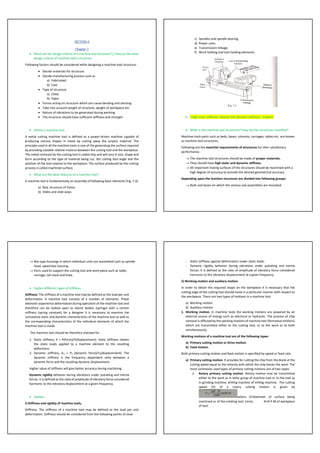
  • 1. SECTION-A Chapter 7 • What are the design criteria of a machine tool structure? // Discuss the basic design criteria of machine tool's structure. Following factors should be considered while designing a machine tool structure: • Decide materials for structure. • Decide manufacturing process such as a) Fabricated. b) Cast • Type of structure a) Close b) Open. • Forces acting on structure which can cause bending and twisting. • Take into account weight of structure, weight of workpiece etc. • Nature of vibrations to be generated during working. • The structure should have sufficient stiffness and strength. • Define a machine tool. A metal cutting machine tool is defined as a power-driven machine capable of producing various shapes in metal by cutting away the surplus material. The principle used in all the machine tools is one of the generating the surface required by providing suitable relative motions between the cutting tool and the workpiece. The metal removed by the cutting tool is called chip and will vary in size, shape and form according to the type of material being cut, the cutting tool angle and the position of the tool relative to the workpiece. The surface produced by the cutting process is called machined surface. • What are the basic features of a machine tool? A machine tool is fundamentally an assembly of following basic elements (Fig. 7.3): a) Bed, structure of frame. b) Slides and slide ways. c) Spindles and spindle bearing. d) Power units. e) Transmission linkage. f) Work holding and tool holding elements. • "High static stiffness reduces the dynamic stiffness"- Explain. • What is the machine tool structures? How are the structures classified? Machine tools parts such as beds, bases, columns, carriages, tables etc. are known as machine tool structures. Following are the essential requirements of structures for their satisfactory performance. → The machine tool structures should be made of proper materials. → They should have high static and dynamic stiffness. → All-important mating surfaces of the structures should be machined with a high degree of accuracy to provide the desired geometrical accuracy. Depending upon the function structures are divided into following groups: → Beds and bases on which the various sub-assemblies are mounted. → Box type housings in which individual units are assembled such as spindle head, speed box housing. → Parts used to support the cutting tool and work piece such as table, carriage, tail stock and knee. • Explain different types of stiffness. Stiffness: The stiffness of a machine tool may be defined as the load per unit deformation. A machine tool consists of a number of elements. These elements experience deformation during operation of the machine tool and therefore can be looked upon as elastic bodies (springs) with a certain stiffness (spring constant) for a designer it is necessary to examine the cumulative static and dynamic characteristics of the machine tool as well as the corresponding characteristics of the individual elements of which the machine tool is made. The machine tool should be therefore checked for 1. Static stiffness, K = P(force)/Y(displacement): Static stiffness relates the static loads applied to a machine element to the resulting deflections. 2. Dynamic stiffness, Kd = Pd (dynamic force)/Yd(displacement): The dynamic stiffness is the frequency dependent ratio between a dynamic force and the resulting dynamic displacement. Higher value of stiffness will give better accuracy during machining. Dynamic rigidity behavior during vibrations under pulsating and inertia forces. It is defined as the ratio of amplitude of vibratory force considered harmonic to the vibratory displacement at a given frequency. • Explain: I) Stiffness and rigidity of machine tools, Stiffness: The stiffness of a machine tool may be defined as the load per unit deformation. Stiffness should be considered from the following points of view: - Static stiffness against deformation under static loads. - Dynamic rigidity behavior during vibrations under pulsating and inertia forces. It is defined as the ratio of amplitude of vibratory force considered harmonic to the vibratory displacement at a given frequency. ii) Working motion and auxiliary motion. In order to obtain the required shape on the workpiece it is necessary that the cutting edge of the cutting tool should move in a particular manner with respect to the workpiece. There are two types of motions in a machine tool. a) Working motion b) Auxiliary motion. 1. Working motion. In machine tools the working motions are powered by an external source of energy such as electrical or hydraulic. The process of chip removal is affected by the working motions of machine tool (formative motions) which are transmitted either to the cutting tool, or to the work or to both simultaneously. Working motions of a machine tool are of the following types: a) Primary cutting motion or Drive motion. b) Feed motion. Both primary cutting motion and feed motion is specified by speed or feed rate. a) Primary cutting motion. It provides for cutting the chip from the blank at the cutting speed equal to the velocity with which the chip leaves the work. The most commonly used types of primary cutting motions are of two types: i. Rotary primary cutting motion. Rotary motion may be transmitted either to the work as in lathe group of machine tool or to the tool as in grinding machine, drilling machine of milling machine. The cutting speed (V) of a rotary cutting motion is given by where D=Diameter of surface being machined or of the rotating tool. (mm), N=R.P.M.of workpiece of tool.
  • 2. ii. Reciprocating primary cutting motion. This type of motion is used in shapers, planers, slotters, power hacksaws and broaching machines. This motion can be transmitted to the tool as in shaper and slotter or to the work as in planer. The speed of return stroke should be kept higher than that of working stroke in order to reduce the non- productive time in machining. The average value of cutting speed(V) is determined as follows: Where L= a Length of working stroke in millimeter. N=Number of full strokes per minute. One full stroke includes a working stroke and a return stroke. b) Feed motion. The rate of feed or speed of the feed motion is substantially less than the cutting speed. The feed motion enables the cutting process to be extended to the whole surface to be machined on the work. Other conditions being equal, the rate of feed determines the cross-sectional area of the chip. The accuracy of the primary cutting motion depends mainly on the design of the main spindle, while the accuracy of feed motion depends upon the design of the bed. 2. Auxiliary Motion. The auxiliary motions do not take part in the process of formation of the required surface but are none the less necessary to make the working motions to fulfil their assigned function. The various types of auxiliary motions in machine tools are as follows: o Engaging and dis-engaging of working motions. o Changing the speed of drive and feed motions. o Clamping and un-clamping of workpiece. The auxiliary motions may be carried out manually or they may be automated in automatic machine tools. • What is slideway? A slide is a moving element providing a straight-line movement to a workpiece or a tool holder at a controlled feed rate. A slide way gives accurate guiding constraints to the slide and may contain some form of adjustments to eliminate play between the two members as wear takes place. • Make neat sketches of different forms of slideways? // Make neat sketches of three different forms of slide and slide ways. Briefly explain them. The common types of slide ways are as follows: 1. Flat slide way: Fig,7.11 shows flat slide ways. They possess a larger load carrying capacity suitable for the larger type of machine They provide a large area of contact; thus, wear is a minimum. It is easier to manufacture such slide way and the geometric feature of these slide ways can be easily checked. On the other hand, they have the following disadvantages a) They require devices for adjusting the clearances b) They have tendency to accumulate dirt. c) They retain the lubricant comparatively poor 2. Vee and flat slide way: Vee ways are more difficult to manufacture than flat ways but are capable of self-adjustment I.e., clearances are automatically eliminated under the action of load. It has no tendency to accumulate dirt. The drawback of the inverted vee type slide way is the lack of bearing surface which results in rapid wear. For lathe bends both flat and inverted vee slide ways commonly used. Fig.7.12 shows a combination of vee and flat ai ways. It is simple to manufacture and is easily rescraped when wear has taken place. 3. Dovetail slide way: They occupy small space. They are commonly used where the cutting forces tend to produce upward movement of slide thus causing vibrations. The gib strip can be adjusted so that the two elements of the slide are a good sliding fit. This type of slide ways is used in center lathe cross slide and compound slide. (Fig.7.13) 4. Roller slide way: In this system (Fig.7.14 rollers retained in a brass cage interposed between the sliding members. This arrangement reduces the friction between the two members of the slide because rolling friction is substituted for sliding friction. Roller slide ways can be used to move heavy load positively and accurately. • Discuss the various factors to be considered for precession of machine tools. The following factors affect the accuracy of finished components made on a machine tool: • Cutting tool geometry • Strength and stiffness of machine tool • Machining variables like: a) cutting speed b) feed c) depth of cut • Accuracy of bearings • Vibrations in machine tool • Nature of workpiece material • Methods of chip removal • Discuss the general requirements of machine tools. Machine tool drives are used to transmit motion from power source to the operative element of the machine tool. The general requirement for the machine tool drives is that they should have provision for regulating the speed of travel of the operative elements. General Requirements of Machine Tool Design: The requirements of a machine tool design are as follows: ▪ High productivity ▪ High accuracy of components manufactured ▪ Safety and convenience of controls ▪ Simplicity of design ▪ Low cost of manufacturing ▪ Low cost of operation ▪ Good appearance • Why box section is more suitable for the beds of machine tools? The box formation is convenient to produce, apertures in the walls permitting the positioning and extraction of cores. It is quite commonly used for lathe beds. Box type section has the highest torsional stiffness and is best suited in terms of strength and stiffness. Also, box section provides a better weight to strength ratio compared to a solid bed. • Classify machine tools. 1. The principal type of machine tools on which cutting tools are used in the modern workshop might be classified as follows: a. Planer, shaper b. Lathe c. Milling machine d. Drilling, tapping and reaming machines e. Broach, saw f. Grinders and polishers g. Gear and thread cutting machines. 2. Degree of specialization. In respect of their degree of specialization the machine tools can be referred to one of the following groups:
  • 3. a. General purpose (Universal) machine tools. They are designed for performing a great variety of machining operations on a wide range of workpieces. They are employed chiefly in piece and small lot production and for repair jobs. b. Single purpose machine tools. They are designed for performing a single definite machining operation. They may be readily set up for machining different sized parts of the same type. Machine tools used for machining crankpins of crankshafts, for turning the cam contours on camshafts are included in this type. c. Specialized machine tools. These machine tools are used to machine a certain definite workpiece by making the necessary changes in their construction. This group includes unit-built machine tools. d. Special machine tools. These machine tools are meant for performing a certain definite operation in machining a certain definite workpiece. Specialized and special machine tools find application in large lot and mass production. 3. Weight. According to weight machine tool can be classified as follows: a. Light weight machine tools. They weigh up to one ton. b. Medium weight machine tools. Their weight varies from 1 to 10 tons. c. Heavy weight machine tools. They weight over 10 tons. 4. Degree of accuracy. According to the degree of accuracy achieved the machine tools are classified as follows: a. Standard accuracy. b. Above standard accuracy. c. High accuracy. d. Precision machine tools. e. High precision or machine tools. • Differentiate between plain and roller bearings. Plain bearings Roller bearings The frictional loss is greater Smaller frictional loss Plain bearings are used where simplicity and cheapness are required, or where a high standard of precision is not essential Used in complex application requiring very high precision They need high initial torque Rolling bearings need reduced torque for starting from rest Less reliable More reliable Difficult to lubricate Easily lubricated High maintenance cost Maintenance cost is low Difficult to replace with new one Easily replaceable • Describe the Plain and Rolling bearing with figures. Rolling Bearings a) Ball Bearings b) Roller Bearings Fig. 7.16 shows a ball bearing whereas a cylindrical roller bearing is shown in Fig. 7.17 and a taper roller bearing is shown in Fig. 7.18. Taper roller bearings have a wide field of usefulness especially in connection with machine tool spindles, gear shafts etc. where high axial and radial forces are combined. One of the methods of increasing the accuracy of ball or roller bearings in the spindle is preloading i.e., they're fitted with very slight interference fits which take up all radial play between the bearing and spindle leaving the only deflections to be those due to elastic stressing This eliminates the clearance between the bearing rings and the balls or rollers and in addition sets up elastic deformation that improves the total rigidity of the spindle unit. Angular contact ball bearing or tapered roller bearings installed in pairs are preloaded by adjustments made during assembly without the need of special devices. The distinguishing features of anti-friction bearings (ball bearings and roller bearings) as compared to sliding bearings are follows: → Low starting resistance. → Low frictional moments and heat generation. → High load capacity per unit width of bearing. → Less consumption of lubricants. → Easy maintenance. Ball bearings are less proof to heating and permit larger speeds. They are less sensitive to small alignment errors. However, ball bearings have higher load capacity. While choosing the type of antifriction bearings following factors should be considered.
  • 4. → Radial and axial run out of spindle. → Radial and axial stiffness of spindle unit. → Heat generation. → Thermal deformation of spindle. → Maximum permissible speed. Plain Bearings A plain bearing is formed when a shaft rotates in a bush, line or the bore of a housing. They are of following types: a) Journal bearing. b) Thrust bearing. c) Combination of journal and thrust bearing. Journal bearing is capable of carrying radial loads whereas the thrust bearing is capable of carrying axial load. Fig. 7.19 shows the behavior of a shaft (journal)in a plain bearing with the clearance. Space filled with oil and the load acting as shown, when the journal is at rest position the oil will drain from the bearing leaving the shaft in metal-to-metal contact with the bearing as shown at Fig.7.19(a). Chapter 8 • What is meant by kinematics of machine tools drive? // What are the kinematic functions of a machine tool? Kinematics is the branch of science related to position and movement. The kinematic functions to be performed by any machine tool are as follows: o To transfer motion and power from the input shaft to the output spindle. o To transfer motion from rotation to translation or reciprocation or vice versa. • What are the different types of drives employed in machine tool? Machine tool drives can be classified according to: ▪ Source of power. ▪ Transmission system. ▪ Nature of motion produced. The machine tools are universally driven by electric motors and further transmission is obtained by any of the following methods: (a) Mechanical drives using belts, gear trains, chains, lead screw and nut etc. In mechanical drives the transmission of motion from external source to the operative element can take place through mechanical elements such as gears, belts, chains etc. Mechanical drives may be of stepless type or stepped type but hydraulic drives and electrical drives are invariably stepless in nature. Mechanical transmission is used for transmitting rotary as well as translatory motion to the operative element. (b) Hydraulic drive. Hydraulic transmission is used in machine tools for providing rotary as well as translatory motion, although the latter application is more common. Hydraulic transmission, as a rule, provides stepless regulation of speed and feed rate. (c) Electrical drive. (d)Pneumatic drive. • What are the basic elements of a machine tool drive? Machine tool drive basically consists of the following: a) an electric motor. b) a transmission arrangement • Discuss about different types of stepped and stepless drive. • Define step ratio? Show that, o = (r– 1) R„R, where the symbols have their usual meanings. Step Ratio: When the spindle speeds are arranged in geometric progression, then the ratio between the two adjacent speeds is known as step ratio or progression ratio. It is denoted by Φ. If N1, N2, N3, ........., Nn are the spindle speeds arranged
  • 5. in geometric progression, then • Explain why arithmetic progression does not permit economical machining at larger diameters. // Explain with the help of a diagram why arithmetic progression does not permit economical machining at larger diameters. Let N1, N2, …, NZ be arranged according to arithmetic progression. Then N2 – N1 = N3 – N2 = constant. If the spindle speeds were arranged in arithmetic progression; the speed spectrum will be as shown in figure. In this case it is observed that speed loss becomes a function of diameter and is larger at lower speeds. It is further observed that there is considerable crowding of speeds at higher speeds. • List the usual values of speed range ratio for various machine tools. • Explain why geometric progression series is preferred in machine tools. // Explain why G.P series is preferred in machine tools.
  • 6. The speeds in gear boxes can be arranged in arithmetic progression (A.P.), geometric progression (G.P.), harmonic progression (H.P), and logarithmic progression (L.P.). However, when the speeds are arranged in G.P., it has the following advantages over the other progressions. a. The speed loss is minimum i.e., Speed loss = Desired optimum speed – Available speed b. The number of gears to be employed is minimum c. G.P. provides a more even range of spindle speeds at each step d. The layout is comparatively very compact e. Productivity of a machining operation, i.e., surface area of the metal removed in unit time, is constant in the whole speed range f. G.P. machine tool spindle speeds can be selected easily from preferred numbers. Because preferred numbers are in geometric progression. • Differentiate a ray diagram from a saw diagram. • What is speed structure diagram? // What does the speed diagram of a gear box indicate? This diagram is developed from the kinetic arrangement of the drive to represent speeds at output as well as intermediate shafts of a gear box. In this diagram shafts are shown by vertical equidistant and parallel lines. The speeds are plotted vertical on a logarithmic scale with log φ as a unit. Transmission engaged at definite speeds of the driving and driven shafts are shown on the diagram by rays connecting the points on the shaft lines representing these speeds. The transmission ratio is expressed in the form of φm, when m is the number of intervals between the horizontal lines spanned by the corresponding ray. If the speeds are written from the bottom to the top in the increasing order of magnitude, then for transmission ratio r>1, the ray is inclined upward and for r<1that is for reduction transmission the ray is inclined downward and for, r=1, the ray is horizontal. Fig.8.9 shows a ray diagram for driving shaft I and driven shaft II which has maximum sped N8 and minimum System N1 Speed structure diagram are of two types: 1. Wide diagrams or open diagrams 2. Narrow diagrams or crossed diagrams • Draw speed spectrum in geometric and arithmetic progression and also differentiate them. • Shows that speed loss remains constant in geometric progression. // Drive an expression for percentage loss of speed in G.P. series.
  • 7. • What is step ratio? How this can help to design an optimum gear box? When the spindle speeds are arranged in geometric progression, then the ratio between the two adjacent speeds is known as step ratio or progression ratio. It is denoted by Φ .If N1, N2, N3, ........., Nn are the spindle speeds arranged in geometric progression, then Gear and Drive • Define direction control valve. A directional control valve is the extend and retract control for your hydraulic cylinders. It is used to direct the flow path of fluid in a hydraulic circuit. A directional valve exists to do three things: stop fluid flow, allow fluid flow, and change the direction of fluid flow. • What are the advantages of spool valve over poppet valve?
  • 8. • Explain the working principle of hydraulic driver for shaper. // Describe the principle of operation of shaper. Fig. 8.39.9 (A) shows the hydraulic shaper mechanism. During forward stroke of the ram the oil under pressure is pumped from the reservoir to the right side of the oil cylinder which exerts pressure on the piston. This causes the ramu9 connected to the piston to perform the forward stroke. The oil present on the left side of the cylinder flows through the throttle valve to the reservoir. On the completion of forward stroke of the ram the reversing dog presses the reversing lever and the positions of the valves (V) is changed. The oil under pressure is then pumped to the left side of the piston and the ram performs the return stroke and any oil present on the right side of piston flows to the reservoir. On completion of the return stroke the reversing dog operates the reversing lever and position of valves (V) is changed and oil under pressure again flows to the right side of the piston and the forward stroke of ram takes place. This way the cycle continues. The return stroke of the ram is completed in less time as compared to forward stroke because the constant discharges oil pump, within a fixed period pumps same amount of oil into the right- or left-hand side of the cylinder and as the left-hand end smaller is due to the presence of the piston rod, therefore the oil pressure will be more on the left-hand end and piston will be moved back at faster speed. Thus, the return stroke will be completed in lesser time. The throttle valve and relief valves are used to change the cutting speed. When throttle valve is partially closed the excess ail flows to the reservoir through the relief valve and a uniform pressure is maintained during the cutting stroke. • Describe different types of direction control valve as used in the hydraulic system. Direction Control Valve is used to direct the flow path of fluid in a hydraulic circuit to a particular path to bring about an operation while cuttings of supply to other path or paths a) Spool type b) Rotary type. Spool type are commonly used. Rotary type valves find application in machine tool table reversals such as in surface and cylindrical grinding machines. Hydraulic reversing is preferred to mechanical and electrical reversing because of the following reasons: → the speed of the response is high → capacity to withstand frequency of reversals is very high.
  • 9. A direction control valve has one inlet port and a number of outlet ports. Depending on ports provided valve is classified as (i) one way valve (ii) two-way valve (iii) three-way valve (iv) four-way valve (v) multi-way valve. These valves are further classified according to number of valve positions such as 2-position valve, 3-position valve. • With the help of neat sketches discuss the working principle of PIV drive. Positive Infinitely Variable (P.I.V.) drive is a positive torque transmission arrangement. In this system there are two chain wheels, an endless chain, a frame, and a screw. The screw has left hand and right-hand threads. The chain wheels have variable pitch circle diameters. One wheel has a pair of cones M and N and other wheel has a pair of cones R and S. The cones can be displaced axially and by doing so the effective diameters can be changed and thus the transmission ratios between shafts A and B are changed) By rotating screw the levered frames get moved thus changing the location of the chain pulley as shown in Fig. 8.34 (α). • Explain with sketches the working principle of a meander type gear box. • Write short notes on: Norton gear box In this gear box different speeds of drived shaft are obtained by engaging the tumbler gear with each gear of gear cone fitted on the driving shaft. The sliding gear is keyed the driven shaft and meshes with the tumbler gear which is held in a bracket pivoted on the driven shaft. This gear box (Fig. 8.25) is widely used as feed gear in engine lathes Vane type motor A vane motor consists of a housing with an eccentric bore, in which runs a rotor with vanes in it that slide in and out. The force differential created by the unbalanced force of the pressurized fluid on the vanes causes the rotor to spin in one direction. A critical element in vane motor design is how the vane tips are machined at the contact point between vane tip and motor housing. Several types of "lip" designs are used, and the main objective is to provide a tight seal between the inside of the motor housing and the vane, and at the same time to minimize wear and metal-to-metal contact PIV Positive Infinitely Variable(P.IV.) drive is a positive torque transmission arrangement. In this system there are two chain wheels, an endless chain, a frame, and a screw. The screw has lefthand and right-hand threads. The chain wheels have variable pitch circle diameters. One wheel has a pair of cones M and N and other wheel has a pair of cones R and S. The cones can be displaced axially and by doing so the effective diameters can be changed and thus the transmission ratios between shafts A and B are changed. By rotating screw, the levered frames get moved thus changing the location of the chain pulley as shown in Fig. 8.34 (a).
  • 10. Sequence valve • What are advantages and disadvantages of hydraulic drive? Advantages: A hydraulic drive has a wide range of speed variation. • In a hydraulic drive both magnitude and direction of speeds can be easily changed. • A hydraulic drive is smooth and reverses without shock. • A hydraulic drive can be operated by a remote control • A hydraulic drive is self-lubricative by transmission • Its design is simple and maintenance is easy. • It is quite in operation. • A hydraulic drive has automatic protection against over loads. Disadvantages: The major drawback of a hydraulic drive is that at low speeds the operation of the hydraulic drive becomes unstable. Secondly, the oil viscosity varies with temperature and may cause fluctuations in feed and speed rates although compensating devices can be introduced to deal with this difficulty. • Explain the hydraulic drive system in machine tool. Hydraulically actuated machine tools offer great flexibility of speed and feed control, elimination of shock and possess the ability to stall against obstruction thus protecting parts or tools from breakage. Hydraulic actuation also permits slip or slowing up of motion when the cutting tool is over-loaded. The important elements of a hydraulic transmission are as follows (e) Pumps (f) Cylinders (g) Direction control valves (h) Pressure valves (i) Throttles. Hydraulic drives are quite commonly used to obtain infinitely variable rates of rectilinear motion in machine tools. A hydraulic drive is rarely used for rotary motion in a machine tool because of its high cost and low efficiency after wear. • Differentiate between stepped and stepless drive. • What is PIV drive? Describe speed gear boxes on the basis of general layout. PIV: Positive Infinitely Variable(P.IV.) drive is a positive torque transmission arrangement. In this system there are two chain wheels, an endless chain, a frame, and a screw. On basis of general layout: ▪ Gear boxes built into the spindle head (or head stock). These gear boxes have the following advantages: o They provide a more compact spindle drive. o There is higher concentration of controls. o They are easy to assemble. Disadvantages: Such gear boxes have the following disadvantages: o Heat produced in the gear-box may heat that spindle head. o Vibration from the gear box may be transmitted to the spindle. These gear boxes are commonly used in medium and heavy machine tools. ▪ Gear boxes with a divided drive. In such gear boxes the gear box and spindle head or head stock are designed as separate units and the gear box is linked to the spindle head through some type of transmission such as belt transmission. Such gear boxes have the advantages that heat produced in the gear box by friction losses is not transmitted to the spindle head and also the vibrations developed in the gear box do not affect the spindle rotation and the spindle runs smoothly. • Explain why four-way valves cannot be operated in single acting cylinder. A single-acting cylinder needs supply to and exhaust from its port to operate. This requires a 3-way valve. A 3-way valve allows fluid flow to an actuator in one position and exhausts the fluid from it in the other position. Some 3-way valves have a third position that blocks flow at all ports. In four-way DCVs, two flows of fluids are controlled at the same time while 2 way and 3-way DCVs control one flow at a time. • Differentiate between metering in circuit and out circuit.
  • 11. • Why closed circuit is not preferable? It is not preferable because- ▪ The exhaust oil return directly to the pump for recirculation, leakage being made up by separate supplies ▪ More expensive components are used ▪ May require high pressure filtration ▪ More difficult to diagnose and repair • Define different types of hydraulic cylinder.
  • 12. • With the help of neat sketches, discuss sliding key mechanism and Norton gear box. This mechanism consists of a hollow shaft into which a slotted rod carrying the key is located and by end-wise movement the rod pulls the key into the key ways of various gears in turn so that any one of a nests of gears is driven by the sliding key. Fig.8.24 shows a sliding key type gear box. This arrangement is commonly used in feed gear boxes of small and medium size drill presses and turret lathes • Discuss the operating principle of four-way direction control valve with neat sketches. • Write short notes on: I) Stepped drive and stepless drive ii) Speed range ratio and common ratio. • Describe with the help of diagram how a four-way valve could be used as a two way. • Classify speed gear boxes and feed gear boxes. SPEED GEAR BOXES: 1. On the basis of general layout: a. Gear boxes built into the spindle head (or stock) b. Gear boxes with divided drive 2. On the basis of speed changing method: a. Speed boxes with change gears b. Speed boxes with sliding gears c. Speed boxes with jaw clutches d. Speed boxes with frictional clutches FEED GEAR BOXES: Feed gear boxes are classified in accordance with the type of geared mechanism, they use to set up the feeds. 1. Feed gear boxes with change gears 2. Feed gear boxes with sliding gears
  • 13. 3. Feed gear boxes with intermediate gear cones and sliding keys 4. Feed gear boxes with gear cone and tumbler gear (Norton gear) 5. Feed gear boxes of the Meander type. • Explain with figure the feed gear box with changing gears. // Explain with neat sketch the feed box with changing gear. • Also discuss about the basic requirements of a speed gear box. The construction of a speed gear box is intimately linked with the whole structure of the spindle drive. A speed gear box should possess the following requirements: a) It should provide the designed series of spindle speeds. b) It should transmit power of an amount dictated by the purpose of the machine tool. c) It should provide smooth silent operation of the transmission and accurate vibrationless rotation of the spindle. d) It should have simple construction. This is characterized to a considerable extent by the total number of shaft gears, clutches bearing and control system components. e) Mechanism of speed gear boxes should.be easily accessible so that it is easier to carry out preventive maintenance and to make the adjustments in bearing clutches etc. MATH 1) A machine spindle is to operate on ferrous metals at 30 m/min and is required to have 6 speeds. The spindle can accommodate IISS cutter ranging from 10 to 60 mm diameters. Determine the following: I) spindle speeds ii) plot a graph between cutting velocity and cutter diameter for each spindle speed and calculate the range of cutting velocity for 12- and 36-mm diameter cutter. 2) A gearbox has six spindle speeds for a machine tool. If the size of the cutter to be used is from 5 to 20 mm in diameter and cutting speed is 21 mm/min. Calculate the common ratio for G.P. series of speed and hence the various spindle speed. 3) A gear box has to be designed for a drilling machine to give speed variation between 120-200 rpm in 6 steps. The input shaft runs at 250 rpm. The intermediate shaft has 3 speeds. Select a suitable gear box layout and calculate the gear sizes. 4) A gear box has to be designed for drilling machine to give speed variation between 100 and 180 rpm in 6 steps. The input shaft runs at 225 rpm. The intermediate shaft has 3 speeds. Select a suitable gear box layout and calculate the gear sizes. 5) Let, Nmin=50 rpm, Nmax=450 rpm and n=9, calculate spindle speeds for G.P series. 6) Let, Nmin = 50 rpm,Nmax = 450 rpm and n=6. calculate the spindle speeds for logarithmic series. 7) A solid steel gear having 24 teeth is to transmit a maximum torque of 20 Kg-m. Determine the module and width of gear.
  • 14. SECTION-B Chapter – 6 • What are the sources of vibration in machine tool? State its effect on machine tool. (6) Vibrations in machine tool Most machine tools vibrate because of mechanical defects. Such defects are always present. A well designed and well-built machine tool operates smoothly because the defects are small but when defects are large, vibrations become excessive. Different parts of machine tool structure are subjected to loading in different ways because of the following reasons: • Changes in workpiece and cutter diameter. • Direction of feed. • Varying depth of cut. Further the moving parts of machine tools do not always move at the same velocity because of wide range of feed and speed combinations. This results in a vibratory system having a very complex dynamic behavior. The vibrations produced affect the machine tool, cutting tool and workpiece. Vibrations in a machine tool occur due to the following reasons: • Un-balanced of rotating parts. • Misalignment of coupling and bearing. • Defective drive (belt, chain gear drive). • Interference in gears. • Self-induced vibrations because of cutting process (tool chatter) is generated and changes its magnitude. • Hydraulic forces. • Aero dynamic forces. • Mechanical looseness or insufficient rightness of fasteners. Effects of vibrations Most of the mechanical defects in a machine tool are positively reflected in the form of vibrations. The amount and type of vibration is proportional to the severity and type of defects. The effects of vibrations can be considered on the machine tool, workpiece, tool life and cutting conditions. • Effects of vibrations on machine tool. Due to vibrations the various parts of machine tool start vibrating and if frequency of vibrations approaches the natural frequency of vibrations of that part, the amplitude of vibrations will be quite high and the part may even break. • Effect of vibration on tool life. Vibrations if present reduce the life of cutting tool by about 70 to 80%. • Effect of vibration on work piece. Due to vibrations the surface finish and dimensional accuracy are affected. • Effects of vibrations on cutting conditions. Due to vibrations the cutting speed does not remain constant. The chip thickness as removed by the cutting tool also does not remain constant and due to this, the cutting forces also vary. Chapter- 7
  • 15. • Discuss types of cutting motion in a machine tool. (7) In order to obtain the required shape on the workpiece it is necessary that the cutting edge of the cutting tool should move in a particular manner with respect to the workpiece. There are two types of motions in a machine tool. a) Working motion b) Auxiliary motion. • Working motion. In machine tools the working motions are powered by an external source of energy such as electrical or hydraulic. The process of chip removal is effected by the working motions of machine tool (formative motions) which are transmitted either to the cutting tool, or to the work or to both simultaneously. Working motions of a machine tool are of the following types: a) Primary cutting motion or Drive motion. b) Feed motion. Both primary cutting motion and feed motion is specified by speed or feed rate. a) Primary cutting motion. It provides for cutting the chip from the blank at the cutting speed equal to the velocity with which the chip leaves the work.The most commonly used types of primary cutting motions are of two types: I) Rotary primary cutting motion. II) A Reciprocating primary cutting motion. Rotary primary cutting motion. Rotary motion may be transmitted either to the work as in lathe group of machine tool or to the tool as in grinding machine, drilling machine of milling machine. The cutting speed (V) of a rotary cutting motion is given by where D=Diameter of surface being machined or of the rotating tool. (mm) N= R.P.M. of workpiece of tool. Reciprocating primary cutting motion. This type of motion is used in shapers, planers, slotters, power hacksaws and broaching machines. This motion can be transmitted to the tool as in shaper and slotter or to the work as in planer. In machine tools using reciprocating primary cutting motion be cutting takes place periodically. In such machine tools the cutting cycle consists of a working stroke during which the tool cuts the chips and the idle or return stroke during which the tool or works returns to its initial position The speed of return stroke should be kept higher than that of working stroke in order to reduce the nonproductive time in machining. The average value of cutting speed(V) is determined as follows: Where L= a Length of working stroke in millimeter. N=Number of full strokes per minute. One full stroke includes a working stroke and a return stroke. The primary cutting motion of certain machine tools may be of a more complex nature. It can also be a combination of rotary and reciprocating motions. Feed motion. The rate of feed or speed of the feed motion is substantially less than the cutting speed. The feed motion enables the cutting process to be extended to the whole surface to be machined on the work. Other conditions being equal, the rate of feed determines the cross-sectional area of the chip. The accuracy of the primary cutting motion depends mainly on the design of the main spindle, while the accuracy of feed motion depends upon the design of the bed. • Auxiliary Motion. The auxiliary motions do not take part in the process of formation of the required surface but are none the less necessary to make the working motions to fulfil their assigned function. The various types of auxiliary motions in machine tools are as follows: o Engaging and dis-engaging of working motions. o Changing the speed of drive and feed motions. o Clamping and un-clamping of workpiece. The auxiliary motions may be carried out manually or they may be automated in automatic machine tools. • Explain types of ribbing with sketches. Why ribbing is used in machine tools.(7) Two basic types of ribbing are as follows: a) Box ribbing. b) Diagonal ribbing. The box formation is convenient to produce, apertures in the walls permitting the positioning and extraction of cores. Diagonal ribbing provides greater torsional stiffness and permits swarf to fall between the sections. It is quite commonly used for lathe beds. Fig. 7.6 shows box ribbing and Fig. 7.7 shows diagonal ribbing. Diagonal ribbing is quite commonly used in medium and large size machine tools. Box type section has the highest torsional stiffness and is best suited in terms of strength and stiffness. The stiffness of machine tool structures life beds, frames, columns etc. can be improved by using ribs and stiffness. The effect of ribs and stiffness depends, to a large extent, upon how they are arranged. Ribbing provides a lighter and stiffer structure than any solid/hollow section. They also help to reduce the effect of vibration on the structure. • Write down differences between plain and roller bearing. (7) Plain bearings Roller bearings The frictional loss is greater Smaller frictional loss Plain bearings are used where simplicity and cheapness are required, or where a high standard of precision is not essential Used in complex application requiring very high precision They need high initial torque Rolling bearings need reduced torque for starting from rest Less reliable More reliable Difficult to lubricate Easily lubricated High maintenance cost Maintenance cost is low Difficult to replace with new one Easily replaceable • Discuss the design criteria for the slide ways of a machine tool. (7)
  • 16. Slideways are designed based on the following: i) Wear resistance: It is governed mainly by the maximum pressure acting on the mating surfaces. This condition may be • Write down differences between machine and machine tools. (7) Machine Machine tools “Machine” is defined as an assembly of mechanisms that are clustered together in such a way that it can perform certain operations by utilizing electrical, mechanical, hydraulic and/or pneumatic power, and thereby reduces the requirement of human effort and intervention in doing the task. A metal cutting machine tool is defined as a power-driven machine capable of producing various shapes in metal by cutting' away the surplus material. Machine consume power to do mechanical work but does not remove material Machine tools remove materials in the form of chips. Machines may or may not be portable. Non-portable Machines do not have a cutting tool. Machines tools almost always utilizes a cutting tool or some kind of abrasive material to remove material. The purpose of machine is to reduce human effort in some application. The purposes of any machine are as follows: • To produce surfaces. • To trace formed surfaces. • To provide a finish to a given surface. • What are meant by stiffness and rigidity of machine tool structure? (7) Stiffness: The stiffness of a machine tool may be defined as the load per unit deformation. A machine tool consists of a number of elements. These elements experience deformation during operation of the machine tool and therefore can be looked upon as elastic bodies (springs) with a certain stiffness (spring constant) for a designer it is necessary to examine the cumulative static and dynamic characteristics of the machine tool as well as the corresponding characteristics of the individual elements of which the machine tool is made. The machine tool should be therefore checked for 1. Static stiffness, K = P(force)/Y(displacement): Static stiffness relates the static loads applied to a machine element to the resulting deflections. 2. Dynamic stiffness, Kd = Pd (dynamic force)/Yd(displacement): The dynamic stiffness is the frequency dependent ratio between a dynamic force and the resulting dynamic displacement. Higher value of stiffness will give better accuracy during machining. Dynamic rigidity behavior during vibrations under pulsating and inertia forces. It is defined as the ratio of amplitude of vibratory force considered harmonic to the vibratory displacement at a given frequency. • What are the slides and slide ways? How they are classified? What are their utilities in machine tools? (7) A slide is a moving element providing a straight-line movement to a workpiece or a tool holder at a controlled feed rate. A slide way gives accurate guiding constraints to the slide and may contain some form of adjustments to eliminate play between the two members as wear takes place The common types of slide ways are as follows: 1. Flat slide way: Fig,7.11 shows flat slide ways. They possess a larger load carrying capacity suitable for the larger type of machine They provide a large area of contact; thus, wear is a minimum. It is easier to manufacture such slide way and the geometric feature of these slide ways can be easily checked. On the other hand, they have the following disadvantages a) They require devices for adjusting the clearances b) They have tendency to accumulate dirt. c) They retain the lubricant comparatively poor 2. Vee and flat slide way Vee ways are more difficult to manufacture than flat ways but are capable of self- adjustment I.e., clearances are automatically eliminated under the action of load. It has no tendency to accumulate dirt. The drawback of the inverted vee type slide way is the lack of bearing surface which results in rapid wear. For lathe bends both flat and inverted vee slide ways commonly used. Fig.7.12 shows a combination of vee and flat ai ways. It is simple to manufacture and is easily rescraped when wear has taken place. 3. Dovetail slide way They occupy small space. They are commonly used where the cutting forces tend to produce upward movement of slide thus causing vibrations. The gib strip can be adjusted so that the two elements of the slide are a good sliding fit. This type of slide ways is used in center lathe cross slide and compound slide. (Fig.7.13) 4. Roller slide way In this system (Fig.7.14 rollers retained in a brass cage interposed between the sliding members. This arrangement reduces the friction between the two members of the slide because rolling friction is substituted for sliding friction. Roller slide ways can be used to move heavy load positively and accurately. Their utilities in machine tools are as follows: • A Slide way gives accurate guiding constrains to the slide. • It may contain some form of adjustment to eliminate play between the two members as wear takes place. • It accommodates the axial movement of the machine slides, worktables and spindles. • Slideway provides the geometric alignment (parallelism, perpendicularity, roll, pitch and yaw) for the axis. • What are the advantages and disadvantages of plain and roller bearings? (7)
  • 17. • What are the elements of machine tool structure? Discuss the basic design criteria of machine tools structures. (7) A machine tool is fundamentally an assembly of following basic elements (Fig. 7.3): a) Bed, structure of frame. b) Slides and slide ways. c) Spindles and spindle bearing. d) Power units. e) Transmission linkage. f) Work holding and tool holding elements. Following factors should be considered while designing a machine tool structure: • Decide materials for structure. • Decide manufacturing process such as a) Fabricated. b) Cast • Type of structure a) Close b) Open. • Forces acting on structure which can cause bending and twisting. • Take into account weight of structure, weight of workpiece etc. • Nature of vibrations to be generated during working. • The structure should have sufficient stiffness and strength • What is meant by static and dynamic stiffness of machine tools structures? 1. Static stiffness, K = P(force)/Y(displacement): Static stiffness relates the static loads applied to a machine element to the resulting deflections. 2. Dynamic stiffness, Kd = Pd (dynamic force)/Yd(displacement): The dynamic stiffness is the frequency dependent ratio between a dynamic force and the resulting dynamic displacement. • Explain why the high static stiffness reduces the dynamic stiffness. • Give reasons why cast iron is mostly used for the production of beds of machine tools. Beds, bases, columns and frames of machine tools are generally made from cast iron because of the following advantages possessed by cast iron:  It has high compressive strength  It can be easily cast into intricate shape  It has better capacity to absorb vibrations.  It possesses good lubricating properties due to the presence of free graphite in it.  It can be machined to a fairly high degree of accuracy and provided a fine surface finish.  It can be easily alloyed with elements like nickel, chromium, molybdenum etc. to increase its hardness.  The cost is fairly low.  Why box section is more suitable for the beds of machine tools? The box formation is convenient to produce, apertures in the walls permitting the positioning and extraction of cores. It is quite commonly used for lathe beds. Box type section has the highest torsional stiffness and is best suited in terms of strength and stiffness. The stiffness of machine tool structures life beds, frames, columns etc. can be improved by using ribs and stiffeners. • Write down the purposes of slide ways. A slide is a moving element providing a straight-line movement to a workpiece or a tool holder at a controlled feed rate. A slide way gives accurate guiding constrains to the slide and may contain some form of adjustment to eliminate play between the two members as wear takes place. The purpose of slideways: • A Slide way gives accurate guiding constrains to the slide. • It may contain some form of adjustment to eliminate play between the two members as wear takes place. • It accommodates the axial movement of the machine slides, worktables and spindles. • Slideway provides the geometric alignment (parallelism, perpendicularity, roll, pitch and yaw) for the axis Chapter- 8 • What is Adaptive control machining system?
  • 18. The adaptive control is basically a feedback system that treats the CNC as an internal unit and in which the machining variables automatically adapt themselves to the actual conditions of the machining process. Adaptive control is the continuous monitoring of cutting load and automatic adjustment of cutting feed rate based on the load. Adaptive control systems respond to random variations in cutting conditions and correspondingly alter the controlling parameter in order to → ensure that the assigned limiting values of process parameters are not exceeded, or → achieve process optimization from consideration of a performance effectiveness criterion. Thus, there are two types of adaptive control systems: a) Limit constraint adaptive control systems b) Process optimization adaptive control systems. • Explain the adaptive control limit constraints process. (8) Fig. 8.40 (a) shows a typical limit constraint adaptive control system for a hydraulic tracer semi-automatic lathe in which there is a limit constraint on consumed power. The input parameters for the operation of the system are limiting power and maximum feed rate. The torque and r.p.m. of the machine spindle are measured and the actual consumed power (PA) is compared with the limiting power (Pm). The difference Pm-PA is amplified and utilized as a controlling signal to regulate the feed rate, which, however, is not allowed to exceed the prespecified maximum value. • Explain the adaptive control optimization process. (8) Fig. 8.40 (b) shows process optimizing adaptive control system from the view point of minimum machining cost as the optimizing criterion. The minimum machining cost is achieved only at an optimum tool life which calls for a control of the tool wear rate. Direct methods of in-process tool wear measurement are as yet not available, and therefore, some indirect method has to be employed. In the system shown, the tool wear has been estimated through the interface temperature measured by a tool-work thermocouple. The various symbols are as follows: TET=Temperature transducer AWR=Algorithm for wear rate calculation AFS = Algorithm for optimum feed and speed calculation DCU = Drive control unit WP = Workpiece. Others 1. With the help of suitable sketch, describe the following terms: I) Counter sinking ii) Carriers and catch plate iii) Reaming iv) Steady rest and follower rest. (others) I) Counter sinking: ii) Carriers and catch plate: iii) Reaming: iv) Steady rest and follower rest: 2. Index 35°29’ using appropriate method and find error. 3. What is meant by indexing? Explain the procedure of angular indexing. Indexing: Indexing is the operation of dividing the periphery of a workpiece into any number of equal parts. It is accomplished by rotating the job through a required angle between two successive cuts.
  • 19. 4. Write short note on: i) Face plate ii) Mandrel iii) Follower rest. (1) i) Face plate: ii) Mandrel: iii) Follower rest: 5. Differentiate between-( 1) • Counter boring and Counter sinking // Differentiate between Counter boring, Counter sinking and Spot facing. counter sinking counter boring Spot facing counter sinking is used for conical drilling counter boring is used for enlarged drilling Operation of smoothing and squaring the surface around a hole counter sinking method produce hole in angular form counter boring method produce hole in circular form A flat surface and right angles with the axis of the hole is created Counter sinking drill unit is radian or degree form counter boring drill unit is meter or mm form counter sinking drill has angle is important counter boring drill has diameter is important counter sinking drill friction is less than counter boring drill counter boring drill friction is more than the counter sinking drill. Highest friction counter sinking process used plastic industry counter boring process used in automobile industry Machine tool parts production • Drilling and Reaming • Shaper and Planer Shaper Planer The work is held stationary & the tool on the ram is moved back and forth across the workpiece. The tool is stationary and the workpiece on the table travels back and forth under the tool. Suitable for shaping much smaller jobs. Meant for larger jobs. Used for light-works. Heavy duty machines. Can employ light cuts and finer feed Can employ heavier cuts and coarse feed Uses one cutting tool at a time Can use multiple cutting tool simultaneously. Uses quick return mechanism to move the ram. Driven either using gears or hydraulic systems.
  • 20. Occupies less floor space Occupies more floor space Easier to operate Difficult to operate About three times quicker than planar Slower 6. What is meant by the term "Process capacity"? Explain how it can be improved. The process capability of a machine tool depends upon its rigidity which is defined as its capability to resist deformation produced due to the introduction of cutting forces generated during machining. A machine tool must possess static as well as dynamic rigidity so that it is able to produce jobs within high degree of accuracy consistently over a long period of time. A machine tool is a group of links (elements) connected in sequence by joints which constitute a closed dimensional circuit. The inherent quality of the element system controls the accuracy and is known as process capability of the machine tool. Process capacity can be improved by using following techniques: 1. By changing rigidity of links. 2. By reducing range of cutting force. 3. By reducing number of links. The production capacity (Productivity) of a machine tool can increased as follows: 1. By decreasing machining time. This is achieved by a. increasing cutting speed or feed. b. machining several workpieces simultaneously. c. concentrating a number of cutting tools in each station. 2. By decreasing handling time. This is achieved by: a. reducing idle number of operations. b. increasing the speed of idle strokes. c. arranging rapid approach or withdrawal of tools or workpieces. 3. By introducing automatic tool changing and bar feeding devices. 4. By using machine tools having good rigidity and strength. 7. Explain the followings: i)Counter Boring, ii) Counter Sinking, and Damping capacity. Damping capacity is a measure of a material's ability to dissipate elastic strain energy during mechanical vibration or wave propagation. When ranked according to damping capacity, materials may be roughly categorized as either high- or low- damping. Low- damping materials may be utilized in musical instruments where sustained mechanical vibration and acoustic wave propagation is desired. Conversely, high-damping materials are valuable in suppressing vibration for the control of noise and for the stability of sensitive systems and instruments. i) Counter Boring: Counter boring is the operation of enlarging one end of an existing hole concentric with the original hole with square bottom. It is done to accommodate the heads of bolts, studs and pins. ii) Counter Sinking: Counter sinking is the operation of making a cone shaped enlargement at the end of a hole to provide recess for a flat head screw or a countersunk rivet. 8. Discuss the importance of studies on: i) Machine tool vibration, ii) Maintenance of machine tool, and ii) Robot. (Others) i) Machine tool vibration: Vibration analysis has proven to be one of the most effective tools for identifying mechanical and electrical faults within machinery. (a) The primary goal of vibration analysis is to identify faults within machine and then alert personnel that some type of action needs to occur. (b) Most machine tools vibrate because of mechanical defects. Such defects are always present. A well designed and well-built machine tool operates smoothly because the defects are small but when defects are large, vibrations become excessive. (c) Whenever the natural frequency of vibration of a machine or structure coincides with the frequency of the external excitation, there occurs a phenomenon known as resonance, which leads to excessive deflections and failure. (d) Most prime movers have vibrational problems due to the inherent unbalance in the engines. The unbalance may be due to faulty design or poor manufacture. Imbalance in diesel engines, for example, can cause ground waves sufficiently powerful to create a nuisance in urban areas. ii) Maintenance of machine tool: Proper maintenance of machine tool helps to extract trouble free service from it. Planned and timely maintenance helps to reduce the breakdown time of the machine tool thereby increasing its availability which ultimately results in better efficiency and higher productivity with the same capital investment and manpower. Time and money spent on planned maintenance will always pay high dividends. Hence the maintenance if carried out at right time in the right quantum at the right cost by the right personnel will go a long way in reducing the cost of production and increasing productivity. ii) Robot: Robots are used in a wide field of applications in industry. Most of the current applications are in manufacturing. The applications can usually be classified into one of the following categories: (1) material handling, (2) processing operations, and (3) assembly and inspection. Apart from being precise and consistent, robots can work in any environment, adding to their flexibility. Robots eliminate dangerous jobs for humans because they are capable of working in hazardous environments. They can handle lifting heavy loads, toxic substances and repetitive tasks. This has helped companies to prevent many accidents, also saving time and money. In the medical field robots are used for intricate surgeries such as prostate cancer surgery. Robots are able to reach and fit where human hands cannot, allowing greater accuracy. Robotic benefits in the medical field can be less invasive procedures and reduce pain for the patient when recovering. 9. Describe simple indexing with an example. It is also named as plain indexing. It over comes the major limitation of direct indexing that is possibility of dividing circumference of workpiece into some fixed number of divisions. In this case worm and worm gear is first engaged. So, one complete turn of indexing crank revolves the workpiece by 1/40 th revolution. LATHE 1. What is backlash in a lathe machine? Backlash can be described as the amount of play between moving parts of a mechanism, and has the potential to appear in almost any mechanical system, particularly gears and lead screws. In mechanical engineering, backlash, sometimes called lash, play, or slop, is a clearance or lost motion in a mechanism caused by gaps between the parts. Backlash can affect both the accuracy and responsiveness of a mechanism, and can also increase wear as loose-fitting moving parts collide together. In systems where a mechanism calculates its own position, backlash can also add up over numerous cycles, resulting in increasingly inaccurate positioning throughout a
  • 21. machine's service life. The issue of backlash is particularly problematic with lead screws, which are generally used in high-accuracy precision actuation - for this reason, components such as anti-backlash lead screw nuts are frequently employed as a preventative measure. Preventing Backlash in Lead Screws: 1. Use Two Nuts: Arguably the simplest way to mitigate the effects of backlash is to use two nuts, spaced apart to press against opposing flanks of the lead screw thread. This method is effective, but can increase costs significantly if using expensive nuts. 2. Use An Anti-Backlash Nut: Anti-backlash lead screw nuts come in a selection of shapes and sizes. Accu offers an anti-backlash nut solution which utilizes an inbuilt compressions spring to ensure that the teeth of a lead screw mechanism remain consistently engaged and preloaded. This method of compensating for backlash is reactive, and can remain effective even if the level of backlash is altered over time 3. Ignore It: Obviously, applications requiring ultra-precise actuation such as 3D printers, CNC lathes, and robotics cannot simply ignore backlash, but for systems where pinpoint accuracy is not a necessity, such as vices, presses or jacks, backlash is not always a significant issue. 2. Discuss various types of lathe machine used in practice. A lathe is a machine tool that rotates a workpiece about an axis of rotation to perform various operations such as cutting, sanding, knurling, drilling, deformation, facing, and turning, with tools that are applied to the workpiece to create an object with symmetry about that axis. Types: a. Engine lathe: refer to a basic type of lathe that may be considered the archetypical class of metalworking lathe most often used by the general machinist or machining hobbyist. b. Bench lathe: A bench lathe is a material reduction machine built into a bench or worktable. A lathe takes a solid block of a material and reduces it to create a symmetrical item. c. Tracer lathe: The tool slide on a tracer lathe is guided by a sensitive, hydraulically actuated stylus that follows an accurate template. d. Automatic lathe e. Turret lathe: It is mostly used in process type layout and repeated production of duplicate parts. These lathes have multiple tools mounted and turret either attached to the cross slide or tailstock which allows quick changes in tools and cutting operations. f. Computer controlled lathe g. Capstan lathe: Lathes with a revolving tool holder which enable several tools to be permanently mounted on it. 3. What is turret? Explain the power transmission mechanism of a lathe machine. The turret lathe is a type of metalworking lathe machine that developed from earlier lathes, adding a turret, which is a kind of indexable tool holder, allowing to perform multiple cutting operations on one machine with different tools, without the need for the operator to do set-up works or control the toolpath. 4. Define different types of work holding and supporting devices used in lathe machine. Various work holding and supporting devices: 1. Lathe centers: work is turned between centers. They support during the metal cutting operations. a. Male centers b. Half-male centers c. Female centers d. V-centers e. Ball-bearing live centers f. Pipe center 2. Chucks: Used extensively for holding work for lathe machining operations. Most important device the w/p, suitable for work of large diameter and unusual shape. Most commonly used lathe chucks: a. Three-jaw universal b. Four-jaw independent c. Collet chuck d. Magnetic chuck 3. Faceplates: These are used to hold work too large or shaped so it cannot be held in chuck or between centers. Faceplates are usually equipped with several slots to permit use of bolts to secure work. 4. Mandrel: They hold internally machined workpiece between centers so further machining operations are concentric with bore. Several types, but most common a. Plain mandrel b. Expanding mandrel c. Gang mandrel 5. Lathe dogs: they work between centers to support long w/p. Lathe dogs has opening to receive work and setscrew to fasten the dog to work. 6. Carriers and catch plates: are known as driving dogs and used to drive the w/p when it is held between centers. 7. Steady rest: used when a long workpiece is machined or drilled. It avoids the undue deflection of the work at the other end. 8. Follower rest: a follower rest performs the same function as a steady rest but it is attached to the saddle and moves along with the tool. 5. Discuss about the role of compound rest in lathe machine. The compound rest (or top slide) is usually where the tool post is mounted. - It provides a smaller amount of movement (less than the cross-slide) along its axis via another feed screw. - The compound rest axis can be adjusted independently of the carriage or cross- slide. - It is used for turning tapers, to control depth of cut when screw cutting or precision facing, or to obtain finer feeds (under manual control) than the feed shaft permits. - Usually, the compound rest has a protractor marked in its base enabling the operator to adjust its axis to precise angles. GRINDING MACHINE 6. Describe the cutting mechanism of grinding machine with figures. Grinding Wheel Cutting Action: During cutting action of a grinding wheel the spacing of the abrasive particles and the effect of the bonding material which holds them in the wheel are very important. Each exposed grain constitutes a small cutting edge thus providing a multiplicity of cutting edges, some having positive rake angles and others having negative rake angles. Each cutting edge acts exactly the same as any other cutting edge under similar conditions with chips being formed (Fig. 5.2). As the cutting edges are small therefore the chips produced are also small. Feed and depth of cut should also be small. In order to achieve close tolerances and excellent surface finish large number of cutting edges, small depth of cut and small feed should be used. 7. Explain the basic principle of centerless grinding operation. Centerless grinding makes it possible to grind both external and internal cylindrical surfaces without the necessity of the workpiece being mounted between centers in a chuck. The principle of centerless external grinding is shown in Fig.5.14.
  • 22. In centerless grinding two wheels are used. The larger wheel called grinding wheel operates as regular grinding speeds and does the actual grinding. The small wheel called regulating wheel is mounted at an angle to the plane of grinding wheel. The work with its both ends freely supported on a vee formed by the work rest, rotates between the grinding and the regulating wheals. The grinding wheel is driven by an electric motor and rotates at a maximum surface speed of about 1850 meters per minutes. Normally, the regulating speed range may lie within 33 to 130 meters per minute. Regulating wheel does not act as a cutting tool but it is mainly responsible for controlling the speed of rotation and longitudinal motion of the work. The wheels rotate clockwise and the work driven by the regulating wheel and having approximately the same peripheral speed rotates counter-clockwise. Axial traverse of the work is controlled by varying the inclination of the regulating wheel. The axial feed is approximately calculated by the formula: f=π DN sin α. MILLING 1. Explain the power transmission mechanism of a milling machine. 2. What is indexing? Mention the name of different indexing methods in milling. Indexing: Indexing is the operation of dividing the periphery of a workpiece into any number of equal parts. It is accomplished by rotating the job through a required angle between two successive cuts. There are different indexing methods in popularity. These are: 1. Direct indexing: It is also named as rapid indexing. For this direct indexing plate is used which has 24 equally spaced holes in a circle. It is possible to divide the surface of workpiece into any number of equal divisions out of 2, 3, 4, 56, 8, 12, 24 parts. These all numbers are the factors of 24. 2. Simple indexing: It is also named as plain indexing. It over comes the major limitation of direct indexing that is possibility of dividing circumference of workpiece into some fixed number of divisions. In this case worm and worm gear is first engaged. So one complete turn of indexing crank revolves the workpiece by 1/40th revolution. 3. Compound indexing: The word compound indexing is an indicative of compound movements of indexing crank and then plate along with crank. In this case indexing plate is normally held stationary by a lock pin, first we rotate the indexing crank through a required number of holes in a selected hole circle, then crank is fixed through pin. It is followed by another movement by disengaging the rear lock pin, the indexing plate along with indexing crank is rotated in forward or backward direction through predetermined holes in a selected hole circle, then lock pin is reengaged. 4. Differential indexing 5. Angular indexing 3. What is the purpose of dividing head of a milling machine? Write down the name of different components of a dividing head. Dividing Heads (often called indexing heads) are machine tools used to provide controlled and repeatable rotation to a tool or workpiece, usually as an accessory to a milling machine, grinder, or lathe.
  • 23. A dividing head, or indexing head, is a machine tool attachment that allows a work piece to be rotated in precise, pre-determined increments for machining of repeated profiles. 12. Discuss its indexing method shortly 13. Is interrupted cutting possible in milling machine? Discuss about the differences between up milling and down milling with necessary sketches. 14. SHAPER-PLANNER 15. Explain the quick return mechanism of a shaper with neat sketches. Why it is necessary?
  • 24. A quick return mechanism is a mechanism to produce a reciprocating motion in which the time taken for travel in return stroke is less than in the forward stroke.
  • 25. DRILLING 16. Name the different types of drill bits. Describe the twist drill with suitable sketches. (1) The Twist Drill: It is used to produce a hole in the workpiece. Its sole purpose is to remove the maximum volume of metal in a minimum period of time. The finish obtained by a drill is not so fine. High carbon steel can also be used to manufacture drills. Drills with cemented carbide cutting tips (tips are brazed) are used at very high speeds for drilling operations on non-ferrous metals but are not recommended for ferrous metal particularly steels because the tips are not supported as effectively as in case of single point cutting tools or milling cutters. A twist drill consists of a cylindrical body carrying two helical grooves into it to from the flutes. The flutes run the full length of body of twist drill and perform the following functions: 1. They provide the rake angle. 2. They form the cutting edges. 3. They provide a passage to the coolant. 4. They facilitate swarf removal. Elements of a Twist Drill: A twist drill is shown in Fig.1.39. The various elements of twist drill are as follows: 1. Body. It is the part of the drill that is fluted and relieved. 2. Shank. It is the part held in the holding device. The most common types of shanks are the taper shank and the parallel shank. 3. Dead center. The dead center or chisel edge of the drill is the sharp edge at the extreme tip end of the drill. It should always be in the exact center of the axis of the drill. 4. Lip. Lip or cutting edge is formed by the intersection of the flank and face. Both the lips of the drill should be of equal length and should be at the same angle of inclination with the drill axis. 5. Flank. Flank is the surface on a drill point which extends behind the lip to the following flute. 6. Chisel edge corner. The corner formed by the intersection of a lip and the chisel edge is called chisel edge corner. 7. Flutes. The grooves in the body of the drill which provides lips. Chapter-10 NC/CNC/DNC • What do you mean by automation and industrial robots? Briefly explain how robot works? Automation is defined as any means of helping the workers perform their tasks more efficiently. By automation the operations are done uniformly and effectively which attain better accuracy and finish. Automation is a technology of working in which handling, methods, process and design of products are integrated to utilize economically justifiable mechanization of thought and effort to achieve automatic and self-regulating chain of process A/C to Robotics Institute of America A robot (industrial robot) is a reprogrammable, multifunctional manipulator designed to move materials, parts, tools, or specialized devices, through variable programmed motions for the performance of a variety of tasks
  • 26. • Define transfer machine? Describe the economics of automatic machines. In transfer machines the processing equipment is arranged in order of the sequence of manufacturing operations. Production lines may be non-automatic and semi-automatic and automatic. In automatic transfer machines the operator loads the blank and usually cheeks the workpiece. These machines are provided with some automatic mechanism lor moving workpieces from station to station to carry out the various operations. Transferring usually is carried out by the following methods: → Rotary transfer system → In-line transfer system. • Differentiate between i) Capstan and Turret lathe Capstan lathe Turret lathe In capstan lathe the hexagonal turret is carried on a slide mounted in a saddle bolted to the bed of the lathe In a turret lathe the hexagonal turret is mounted on a slide directly on the bed In capstan lathe the turret heat is mounted on a short slide with only a limited amount of travel In turret lathe the turret saddle bears directly on the bed of lathe and therefore can traverse full length of the bed if required A capstan lathe is usually a small or medium size machine the turret lathe is suitable for long and heavy work Capstan lathe is suitable fur bar work larger and heavier chucking works are generally handled on a turret lathe It is easy to move the ram for feed Ịt is difficult to move the saddle for feed It is used for machining workpieces up to 60mm diameter. It is used for machining workpieces up to 200mm diameter. Collet is used to holding the workpiece Jaw chuck is used to hold the workpiece • What is an automatic machine? State the factors which affect the classification of automatic machines? Automatic machines are used to increase production rate. In such machine both the workpiece handling and metal cutting operation are performed automatically, The classification of the automatic machines depends upon following factors:  Nature of work  Type of blank to be machined  Operation to be carried out  Processing capacity  Machining accuracy desired  Design features. Discuss the advantages of transfer machine. Advantages The various advantages of transfer machines are as follows:  Higher production rates are achieved.  Less floor space is required.  Less number of operations are required.  The quality of products is considerably improved.  The length of production cycle is reduced Disadvantages  The initial cost of transfer machine is high. It is of great importance that the construction of components to be machined on transfer machine should remain stable for sufficient time to justify the cost of such machine.
  • 27.  Much time is required to change over the machine to k a different shaped component.  A breakdown of one machine means stoppage of whole of than line. 17. Explain the two basic systems of numerical control with figures. // Describe with necessary sketches, the principle of functioning of open loop and closed loop NC machines The two basic system of numerical control as follows: a) Open loop system b) Closed loop system Open Loop System. This system does not have a feedback device and therefore the actual position of the tool side or work table is not measured and verified. As shown in Fig. 10.22 the information is fed from the operator control console to the tape reader which picks off the discrete bits of information from the tape and then feeds them to the distribution control unit the information is then directed to the servo control unit for a particular axis (X-axis,Y-axis,Z-axis etc.) control and finally the command is transferred to the servo-motor in the form of electric impulses or signals. The servo-motors control the machine table (slide)movement, the cutter head movement etc. Closed loop system. This system is generally used because this system ensures that the slides have taken up the desired position (Fig. 10.23). This is done by measuring the actual position of the slides by transducer attached to each axis. The transducer converts the motion as directed from linear or rotary motion to an electrical impulse. This impulse is fed back to the control unit as å check on the input signal. There should be no difference between input signal and feedback signal. If there is any difference between the two, the correction is made by comparator and then the operation is carried out The basic elements of a N/C machine tool system and their functions are carried out by control loops. The command is given by. the tape reader through the data processing unit and the drive mechanism carries out the intended work. The drives can be either electrical or hydraulic. The control loop is the link between the command and the drive. The open loop system is cheaper in investment, maintenance and operation but may become expensive if very high accuracy is required which will demand very specialized equipment. For contouring N/C systems, closed loop drives are to be preferred for obvious reasons. Straight line contouring can actually be carried out with open loop systems, but in general a closed loop. N/C will be more effective, more accurate and more suitable for nearly all operations. • Define NC. State the advantages and disadvantages of numerically controlled machine tools over conventional machine tools. Numerical control (NC) is considered to be an improved control for machine tools that provides higher productivity. Numerical control is a method of controlling of motions of machine tool components by means of coded instructions in the form numbers on tapes or punch cards. Advantages. The various advantages of numerical control are as follows:  A greater accuracy is achieved.  High production rates are obtained.  Expensive jigs and templates are not needed. This reduces the tooling cost.  Time required for setting up the machine is reduced.  The amount of human error is greatly reduced and therefore the scrap rate is decreased.  Programming and tape writing takes much less time than making jigs and fixtures and locating gauges. Also the tapes last longer and require much less space than jigs and fixtures.  Operation of the machine does not require a skilled operator. Except for positioning the workpiece on the table, the human element is completely eliminated.  The cutting time of total cycle time is as high as 80% in case of N.C. machines as compared to about 30% in case of conventional machines. Disadvantages.  Initial cost of numerical controlled machine tools is high.  Machine tools should be rigidly built than conventional machine tool in order to withstand accelerations dictated by servo controls.  Skilled electronics technicians are needed to maintain the electronic controls. • Explain the basic components of an NC system. Basic Components of an N.C. System The basic components of an N.C. system are as follows:  Program of instructions. It is a set of directions which will tell the machine tool what to do. It is coded in numerical or symbolic form on some type of input medium such as one-inch-wide punched tape.  Controller unit also called machine control unit (MCU). It consists of the electronics and hardware that read and interpret the program of instructions and convert it into mechanical action of the machine tool. The various elements of MCU are as follows: o Tape reader. o Data buffer. o Signal output channels to the machine tool. o Feedback channels from the machine tool.  Machine tool or other controlled process. It performs the useful work. A machine tool consists of the following: o Work table and work fixtures. o Spindle. o Cutting tools. o Motors and controls for drives. o Other auxiliary equipment needed in machining operation. 18. Describe the BTR approach of DNC system with necessary figures. BEHIND-THE-TAPE-READER (BTR) SYSTEM. In this arrangement, pictured in Figure 9.6, the computer is linked directly to the regular NC controller unit. The replacement of the tape reader by the telecommunication lines to the DNC computer is what gives the BTR configuration its name. The connection with the computer is made between the tape reader and the controller unit—behind the tape reader. Except for the source of the command instructions, the operation of the system is very similar to conventional NC. The controller unit uses two temporary storage buffers to receive blocks of instructions from the DNC computer and convert them into machine actions. While one buffer is receiving a block of data, the other is providing control instructions to the machine tool
  • 28. • State the basic features of point-to-point and continuous path control system. Numerical control programming can be divided into two main systems as follows: a) Point to point (PTP)system. b) Continuous path system. Fig. 10.24 (α) shows point to point system and Fig. 10.24 (b) show continuous system.  Point to point or Positioning System: Point to point control is used in vertical drilling machines, jig, bores and tapping machines. The object of this system is to move a machine tool table (and hence the work) through rectangular coordinates according to a programme so that the different machining operations are carried out at the programmed points where the table stop.  Continuous Path System or Contouring System In this system tool remains in contact with the work and generates a continuous surface in space. In this system the position of tool relative to the workpiece must be continuously controlled while workpiece is being machined. This system is used in milling machines. The preparation of part programme for NC machine tools with contouring controls is more complicated than for those with finite positioning controls. Coordinate positional control is used in drilling, jig boring, turret drilling and milling, Continuous path control is used in milling or flame cutting contours, grooving, boring, and cam milling. In the contouring systems the simultaneous movements of the tool and workpiece are coordinated to generate the desired profile. Contouring NC machine tools can machine not only straight lines at angle but also complicated profiles. The profile is approximated by elementary straight lines, arcs of circles or segments of parabola to describe the locus of tool cutting edge. Generally, all contouring N.C. machine tools are equipped with a feedback arrangement. Contouring N.C. machine tool are expensive than point to point control principled machine tools. 19. What are the differences between CNC and DNC system? // Compare CNC with DNC. In CNC, remote controlling of operation is not possible. DNC facilitate the remote control. CNC is an integral part of the machine. DNC is not integral to machines; DNC computer can locate at a distance from machines. CNC transferring machining instruction. DNC manage the information distribution to the number of machines. CNC computer control one NC machine. Using DNC programmer can control more than one NC machine as required. CNC have low processing power when compared to DNC DNC have high processing power when compared to CNC CNC software is to increase the capability of the particular machine tool. DNC not only control the equipment but also serve as a part of management information system. 20. State the functions of MCU. Controller unit also called machine control unit (MCU). It consists of the electronics and hardware that read and interpret the program of instructions and convert it into mechanical action of the machine tool. Other functions include: 1. Part-program storage 2. Part-program graphical proving and editing 3. Part-program generation using conversational part-programming methods 4. Tool-life management function, which includes larger number of tool offset registers as well as monitoring the life of the individual tools used 5. Background part-programming methods 6. Drip feeding of part programs when they are very large in cases such as finish machining of 3D contours of dies and molds 7. Enhanced part-programming facilities 8. Better interfaces to the outside world 9. Diagnostic facilities with the probability of direct linking with service centers using modems 10. Enhanced machine control such as adaptive control, lead screw pitch error compensation, thermal compensation, etc. 21. Briefly explain the NC systems of a machine tools. Numerical control (NC) is considered to be an improved control for machine tools that provides higher productivity. Numerical control is a method of controlling of motions of machine tool components by means of coded instructions in the form numbers on tapes or punch cards. The basic components of an N.C. system are as follows:  Program of instructions. It is a set of directions which will tell the machine tool what to do. It is coded in numerical or symbolic form on some type of input medium such as one-inch-wide punched tape.  Controller unit also called machine control unit (MCU). It consists of the electronics and hardware that read and interpret the program of instructions and convert it into mechanical action of the machine tool.  Machine tool or other controlled process. It performs the useful work. NC Procedure: 1. Process planning 2. Part programming 3. Tape preparation 4. Tape verification 5. Production The success of N.C has led to a number of extensions of numerical control concepts and technology. Four of the more important developments are following: 1. Direct numerical control (D.N.C.) 2. Computer numerical control (C.N.C.) 3. Adaptive control (A.C.) 4. Industrial Robots NC technology has made it possible to reduce cost of production by reducing the production time. This in turn is mainly directed towards the reduction of non-productive time such as a. setup time b. work piece handling time c. tool change time d. lead time. Other features of NC machine tools are: a. reduced fixturing b. ease of making workpiece design changes c. improved accuracy d. reduced human error e. greater manufacturing flexibility
  • 29. 22. Write short note on: i) MCU, ii) industrial application of robot, iii) Functions of CNC system. Machine Control Unit (MCU) Every N.C. machine tool is fitted with a machine control unit (MCU). The MCU may be mounted on the machine tool itself or it may be boused in a separately standing cabinet like body. The MCU can be considered as a special purpose computer that executes the commands mentioned in the part program i.e., the program to manufacture a part on the N.C. machine tool. This program, of course, is in the form of an acceptable input medium like paper tape, and magnetic tape, the paper tape being quite commonly used. The MCU converts the information from the tape program into desired command signals used in the actuation system of the machine tool. Controller unit also called machine control unit (MCU). It consists of the electronics and hardware that read and interpret the program of instructions and convert it into mechanical action of the machine tool. The various elements of MCU are as follows:  Tape reader.  Data buffer.  Signal output channels to the machine tool.  Feedback channels from the machine tool. Application areas for industrial robots Industrial robots have been applied to a great variety of production situations. For purposes of organization, we will divide the applications into the following seven categories: 1) Material transfer 2) Machine loading 3) Welding 4) Spray coating 5) Processing operations 6) Assembly 7) Inspection Functions of CNC The principal functions of CNC (Computer Numerical Control) are as follows:  Machine tool control. This involves conversion of the part program instructions into machine tool motions through the computer interface and servo system.  in-process compensation. This involves the dynamic correction of the machine tool motion for change or errors which occur during processing.  Improved programming and operating features. It helps in achieving the following: → Editing of the part programs at the machine. → Graphic display of the tool path to verify the tape.  Diagnostics. The N.C. machine tools are complex and expensive systems. The complexity increases the risk of the components failures which lead to system down time. CNC machines are often equipped with a diagnostic capability to assist in maintaining and repairing the system. 23. Differentiate between- a. Absolute system and Incremental system b. Fixed zero point and floating zero point In absolute system to the co-ordinates are mentioned in the program with respect to one reference point (Datum). In incremental system the co-ordinates of a point are mentioned in the program with respect to the previous point. An absolute system is one in which all position commands are referred to one reference point, which is called the zero point. When considering an incremental system both the programming and the feedback elements are incremental. A typical feedback device is the rotary encorder which provides sequence of serial pulses. Fig. 10.31 indicate the typical position of points A, B and C and their co-ordinate are indicated in Table 10.4 Zero System. The point where X, Y and Zaxes cross is called zero point. A machine tool may have two types of zero point.  Fixed zero point. The fixed zero-point machine is usually made so that the zero location is at the low left-hand corner of X-Y ordinate on some systems the fixed zero may be moved by means of switches or dials to anywhere within the full travel range of the machine.  Floating zero point. It allows the operator to place the zero at any convenient location without regard to the initial fixed zero point. The operator merely moves the table to the desired location by means of jog buttons. The jog buttons make it possible for the operator to manually move the table to the desired location at feed rates set on the dial. When the table is at the exact desired location, the operator depresses a button which establishes this point as the zero point. • NC vs. CNC Sl. No NC Machine CNC Machine 1. NC stands for Numerical control machine. CNC stand for computer numerical control machine. 2. Here Punch card is used for storage. There is no memory storage card here. Memory storage is present because of the computer system here. 3. In the NC machine, the operation parameter cannot be changed once indexed but In the case of the CNC machine, the operation parameter can be changed easily. 4. NC machine works X-Y and straight-line axis. CNC works on the X-Y-Z axis. 5. NC machine is less costly. CNC machine is more costly. 6. It requires less maintenance. It requires require more maintenance. 7. In terms of accuracy, NC machine is less. Whereas the CNC machine has good accuracy. 8. NC machines are less flexible. CNC machines are more flexible. 9. The operation time is more here that means time The operation time is less here.
  • 30. taking is more for performing the operation. 10. A good or skilled operator require to perform on the NC machine. A semiskilled can perform on the CNC machine. The main things are users must have knowledge of computer system 11. The continuous running of machine is not possible but Here the continuous running of machines is possible. 12. For the execution of a job, the NC machine takes more time. CNC machine takes less time. 13. The NC machine works on only numeric, symbol and letters. This CNC machine works on G and M code. 14. NC machine understands numeric, symbol. It understands binary data (1s, 0s). 15. This is hardware-based type system. This is software base system.