SlideShare a Scribd company logo
1 of 59
FUNDAMENTAL OF MACHINE TOOLS
Machine Tools :
 Power operated machine
 Expend energy to cut metal
 Metal removed from blank in form of
chips to develop required product
 Required finish and accuracy of the part is
to be maintained
 Uses cutting tool
 Non portable
Example :- Lathe, Milling, Broaching and so
many…
Operations :
Hold the blank.
Hold cutting tools.
Different types of motion-linear, rotary,
combination or intermittent as needed for
different parts.
 Input- Information of job shape, size
-work shape, size, material
- energy machine tool information
 Output- Required shape size accuracy
-finish and integrity of surface
-rate of production, mfg cost/piece
input output
machine tool
operator feed back
to operator
Man machine system
Lathe Machine Drilling Machine
CLASSIFICATION
Based on Field of Application
i. General purpose: Highly flexible, wide
range of work-piece Variety and
material, cost effective job Production.
Ex-plain turning lathe, turret lathe,
milling & grinding machine etc.
ii. Production purpose: Less flexible, work
variety and material limited, cost
effective batch and mass Production.
High power and rigid. ex- multi tool
lathe, plunge cut grinder etc.
iii. Specialized: Same shape but different
size product. Readily can be switched
overfrom one job to other. Ex-
iv. Single purpose: Specialized for a definite
machining operation. Ex. Thread cutter,
gear hobber etc.
v. Special machine tool: Tool grinder,
threading by die tap etc.
 Based on Configuration
Horizontal, Vertical, Inclined.
 Based on Primary Machining Operation
Turning, Milling, Grinding, Combination
machine tool
Based on Nature of Cutting Motion
Rotating tool/Reciprocating tool
According to Accuracy
Normal Accuracy: Majority of components
Higher Accuracy: Critical parts requiring
assembly and alignments
Precision: More stringent accuracy and narrow
tolerance
Based on Environment
Heavy duty: >10kw, continuous running
Medium duty: 3-10kw, medium load
Small duty: <3kw, small load and minimum
time of running.
Based on Degree of Automation
Manual-control
Semi Automated-
Automated-
Major Components of Machine Tools
 Components for holding tool and workpiece.
 Prime mover to provide power.
 Kinematic chain for transmission and
transformation of power.
 Structural body sufficient to support dead
and live load within specified limit.
 Proper control and automation systems.
Specification of Machine Tools
It is the parameters to express the
functional requirements of the machine
Tools. Generally they are_
 Size limit of the work
 Maximum and rated power
 Spindle speed-range, no of divisions
 Feed ranges
 Floor space , weight etc.
 So many others
Types of Motion in Machining
 i)Primary Motion: It serve the purpose of
removing metal. It has two types.
a)Principal/Cutting Motion: Depends on
optimum cutting speed for tool work-
piece combination and nature of
machining. It may be rotary, linear or
combination of both.
b)Feed Motion: Depends on required
finish of the product. It may be
continuous, intermittent, compound.
 ii)Auxiliary Motion: It help to accelerate
other processes involved in production
apart actual machining. This motion may
be hand driven or automated. Ex-
changing of speed and feed, clamping and
unloading of work in the machine tool etc.
Performance Criteria of Machine Tools
 Safety
 Ease of Operation: Less fatigue for operation,
loading, unloading and bringing tool and w/p in
engagement should be easier by automation or
quick acting clamp etc.
 Production Accuracy: Geometric, locational and
dimensional accuracy with surface integrity as
per requirement. Possible if machine tools is
designed with sufficient stiffness and alignment
and manufacturing accuracy of components.
 Production Capacity: Max. no. work-piece per
unit time would be as per required.
 Reliability and Maintainability
 Ease of Maintenance
 Compactness: Should be high, fixed and
operating cost should be as low as possible.
Cost Effectiveness of Machine Tools
1
2
3
Cost
Of
Prdn.
Rate of production
1.General purpose
2. NC Mahines
3.Special purpose machine
General Feature of Construction of Different Parts and Working of Lathe
 Oldest and important machine tools.
 The principal surface developed is
cylindrical surface.
 Job is rotated (turned) and tool slides
relative to job. So it is turning.
 Cutting Speed: V=Πdn/1000 m/min; d in
mm , n is rpm.
 d=Depth of cut =b cos( ); is Side
cutting edge angle, b=Width of cut.
 f=Feed in mm/rev
 But many other operations like facing,
parting, taper turning and so on is
performed by this machine tools.
 So it is termed as “The father of machine
tools family.”
s
 s

Construction of Lathe and its Components
 Power Transmission: Transmitted through
series of kinematic chain/mechanism_
• Simple train: Individual motion has
individual power. Found in modern
machine tools.
• Complex train: different motion and
power from single power source.
• Compound train: combination of simple
and complex train.
A lathe is typically consist of basic components
like-
Headstock: It is fixed at the left end. It
houses power source, power
transmissions and spindle.
 Power Source:
• Induction having one or two fixed speed
for stepped variation.
• Variable speed induction motor, dc motor
for stepless drive.
• ac and dc servo motor, stepper motor for
NC, CNC Machine.
 Power of Motor: Is to be estimated to
overcome power for machining, friction,
inertia forces, auxiliary motion etc.
 Spindle:
• It imparts rotary motion, hold centres/work
holding devices/ work/ tool as required.
• It is hollow to take long bar stock.
• It has an external tapered surface at the front end
to locate driving plates/chucks.
• Front side has taper bore to accommodate
centres.
 Centres:
• The centre held in spindle is known as live centre
having an included angle 60 degree as they rotate.
• Live centre is mounted on ball bearing/tapered
roller bearing along with thrust bearing.
• It is also preferred during high speed machining to
reduce frictional heat generation.
• Centre used in tail stock is called dead centre as it
does not rotate. May be of normal, half ended for
turning and facing operation, spherical ball ended
centre to accommodate set over.
• The centre in tailstock is subjected to heavy wear
due to relative velocity between centre and
workpiece. Wear resistance can be increased by
tipping the point with cemented carbide or wear
resistant alloys.
Tailstock:
• Function is to hold dead centre which
supports long work piece (l/d>4).
• It is clamped on the right side of bed.
• It consists of two parts. Lower part rests
on bed ways and upper part rest on lower
part.
• Lower part along with upper one can be
slide over bed through guide ways to
accommodate different length as
required.
• Adjustable screw holds two part together.
• By loosening it, upper part can be moved
away or towards the operator to offset
tailstock.
• The body of the tail stock has a bore for
hollow cylindrical sliding member known
as quill.
• Drills, reamers, tap and other tools are
held and fed to the workpiece by the quill.
 Carriage:
• It is moveable components between head stock
and tail stock.
• Its prime function is to hold the cutting tool and
to provide required relative motion to the
cutting tool (Longitudinal feed and Cross feed).
• It includes five major components like –saddle,
cross slide, compound rest, tool post and apron
mechanism.
 Saddle: Base of carriage, slides longitudinally
along the bed ways.
 Cross Slide:
• Mounted on saddle by means of dovetail ways.
• Provide cutting tool motion in cross direction
which may be controlled manually by handle or
by power feed.
 Compound Rest:
• It has a graduated base that can be swiveled
around vertical axis so that it can be angled with
axis of workpiece.
• So it is used for angular cut, specifically in case of
short taper.
• In order to achieve good performance of
machine tolls, its supporting structure
must be designed with sufficient strength
and stiffness.
• In order to absorb vibrations, it is made as
a rigid casting part.
• Deformations and stresses developed due
to torsion and bending depends on size
and additionally on shape.
• The section providing maximum moment
of inertia and sectional modulus should
be selected. And hollow box type section
is the best.
• The top of bed is planed to form
guideways.
• These are the rails on which
complementary part slides.
• Less expensive and low duty lathe have
flat ways while medium to heavy duty
lathe have combination of 2 pairs of
guideways to provide motion to saddle
and tail stock.
 Tool Post:
• It is mounted over compound rest in a T-
slot as shown.
• It can be adjusted to tilt with the help of a
concave ring collar and rocker base.
 Apron:
• It contains Apron Mechanism reduction of
speed and rotary to linear conversion of
speed.
• It lies under the saddle in front side of
lathe.
• https://www.youtube.com/user/munmachi
neshop go for setting and working.
 Bed:
• Bed is the base of lathe which supports all
other components.
• During cutting operations, majority of
structures are subjected to complex loading
like-combinations of torsion, bending,
tension or compression which results
accountable deformations leading to
question on accuracy of parts.
Speed Changing Methods:
i) By Shifting Key
ii) Ruppet Drive
iii) Pre-Optive Drive (variable position clutch )
iv) Engaging Clutch
v) By Shifting Cluster Gears.
Engaging Clutch-
Drive System: Mainly two types_
• Primary Cutting Motion and Feed Motion.
• Primary cutting motion drive enable to
achieve certain speed range and variation
for spindle.
• Feed motion drive enable to achieve
range and variation of feed in linear
motion.
Primary Cutting Motion Drive/Spindle Drive:
• In general geared head stock drive is
designed to get stepped variation in
spindle output in multiple of 2 and 3 i.e;
3,4,6,8,12,16 and 24.
• As no. of variations become more,
complexity of drive arises.
• Variations are arranged in geometric
progression with common ratio 1.06, 1.12,
1.26, 1.41, 1.58 and 2. ( as c.r increases
productivity loss increases and as c.r
reduces more variation and complex
design).
• Common ratio where z
is no of step. min
max
1
N
N
z



By Shifting Cluster Gears:
• A set of gears which can be slide on shaft
to mesh with required gear is known as
slider gear or cluster gears.
• Gear 1, 2 and 5,6,7 are cluster gear.
• Corresponding ray diagram is shown
which indicates six number of speed
variation in output spindle.
Some Criteria:
• Fixed gears spacing must be > 2b. (b width
of gears)
• Minimum difference in teeth of adjacent
gears in a cluster must be => 4.
• Minimum no. of teeth in gears for speed
box => 20.
Advantage: It is more efficient and compact ,
able to transmit high power, available
power for all types of speed remains
almost same.
Back Gears:
i. For low duty smaller lathes, power transmits from motor to the cone pulley mounted on
spindle by means of belt.
ii. Spindle speed is changed by shifting belt to different pulley.
iii. In order to get more variations and minimum speed back gears are used.
iv. Cone pulleys and gear A is mounted on sleeve on spindle helps to rotate freely.
v. Whenever lock pin is engaged, rpm is directly drives spindle, as gear B is rigidly mounted on
spindle and N1, N2, N3 are obtained.
vi. When back gears C and D are engaged with A and B respectively and lock pin E is disengaged,
motion is reduced to N4, N5 and N6 with transmission ratio . i.e; N4 = N1 X
B
C
D
A
Z
Z
Z
Z


B
C
D
A
Z
Z
Z
Z


Feed Box:
Work at very low velocities and does not pose serious vibrational problems.
There are large number of speed reduction ratio and feed steps than speed box.
Rotary to linear conversion and may be continuous or intermittent.
Feed drive in lathe consist of_
(a) Reversing Mechanism (b) Change Gear Quadrant
(c) Quick Change Gear Box (d) Lead Screw
(e) Feed Rod (f) Apron Mechanism
 Reversing Mechanism:
• Function is to reverse the direction of lead
screw/feed rod , thereby reversing the
direction of feed.
• Consist of four spur gears with
consecutive engagement of the bracket
holding reverse gears.
• Gear z2 and z3 are freely mounted on stud
iii and iv of the bracket which is mounted
on shaft ii.
• Feed reverse lever can be moved to three
positions 1,0,2.
 Change Gear Quadrant:
• It is two pair gear arrangement
with a quadrant proper.
• It serves to set up feed drive to
different speed of lead screw and
feed rod.
• It is employed in cases, when it is
necessary to obtain precise
transmission ratio for required
generating motion.
• The set of change gears are chosen
so that almost practically all
transmission ratio can be obtained.
• Z2 and Z3 are keyed on a sleeve
which can be mounted freely on
stud E which can be adjusted and
clamped along the slot to
compensate centre distance.
• For the given case, gearing ratio is
4
2
3
1
z
z
z
z


 Quick Change Gear Box:
• The quick change gear box is located in
front side below head stock.
• Function is to rapid change in (a)Feed
rate (b) rpm of spindle/ feed rate by
shifting corresponding lever.
• It contains (i) A number of different size
gears (ii) Intermediate gear
(iii) Tumbler gear (iv) A chart.
• The tumbler gear can be slide over
shaft to mesh any gear on shaft I via
intermediate gear mounted on shaft II
by swinging and sliding lever.
• Shaft III on which tumbler gear is
mounted is the driving shaft.
• The number of gears in cone = number
of transmission required.
• Positive Features:
i)Compact design to enable large number of
transmission in single group.
ii)Simple control by using single lever.
iii)N feed rate can be found by using N+2
gears only.
• Negative Features:
i)Insufficient rigidity and accuracy of
meshing.
ii)Poor lubrication.
iii)Possibility of dirt accumulation in housing.
Specification of Lathe:
1. distance between centre.
2. swing over bed: max. dia of job that can be
turned.
3. swing over cross slide: max dia of work
turned with job cross slides.
 Apron mechanism:
• Main function is to transfer rotary to linear
motion with subsequent speed reduction.
• Feed rod 2 has a keyway along its whole
length.
• Worm 3 with its key slides along the rod.
• Worm mesh with worm wheel 4 and
motion transferred to pinion 5 mounted on
same shaft.
• By turning automatic feed knob pinion 5
meshes with gear 6 and rotation transfers
to pinion 7 which runs on rack fastened to
bed.
• It is employed for turning and other
operations.
• For thread cutting, instead of feed rod lead
screw take active part. By changing feed,
change lever to neutral position feed rod
become inoperative and Lead screw active.
• Lead screw feed the carriage through two
half nut mounted at the rear wall of Apron
when engaged.
Work Holding Devices
Primary Functions:
• To hold work-piece at suitable location
by effective clamping.
• Used for different machine tools.
• Work holding devices in lathe- centre,
chuck, collect, face plate, mandrel, steady
rest, follower rest, mandrel etc. are used
depending on shape, size, location of
work-piece.
Chucks:
• Chucks are available in many style and
types.
• Size wise it also varies from small drill
chuck to massive lathe chuck.
• It have long been useful work holding
devices for variety of cylindrical work.
• Development of novel accessories and
their implementation in standard chuck
make it more useful.
 Three Jaw Chuck:
• 3 jaws move inward or outward
simultaneously by same amount.
• Jaws are 120 degree apart.
• Known as self centering chuck.
• Although quick centering but limited
gripping force; so not suitable for heavy
or precise work as accuracy 0.125 TIR(
Total indicated run out)
• Mechanism involve combination of bevel
gear drive and a spiral rack(scroll plate).
By turning the bevel pinion, scroll plate
rotare and rotation of scroll plate move
jaws by meshing flat teeth behind jaws
with spiral rack.
 4 Jaw Chuck:
• The independence of the jaws movement.
• Make this chuck suitable for holding even
non-circular part, heavy part with greater
clamping force and reasonably greater
accuracy than 3 jaw.
• Individual jaw can be moved radially over
its slot by rotating individual jaw screw.
 Magnetic Chuck:
• Magnetic chucks is used to hold magnetic
material (iron/steel).
• Parts are thin and prone to damage under heavy
clamping force.
• Chuck is used when light cut and special grinding
operations.
• Chucks are fitted to an adapter mounted on
spindle.
• For aligning work is held lightly by turning chuck
wrench a little bit. Then work is trued and chuck is
turned full-on-position to hold job securely.
• https://www.youtube.com/watch?v=vfhZnJWlcb4
 Collet Chuck:
• Most accurate and used for precise job.
• Each collet has a range of 100ths. of mm.
over or under the size marked on it.
• Variety: Spring Collet Chuck & Jacob Collet
Chuck.
• Jacob collet has wider range of work.
• Hold round, square or hexagon shape very
fast. Limited to smaller job.
• In the taper of head stock spindle, a special
adapter is fitted.
• A hollow draw bar with an internal thread is
inserted in opposite end of spindle.
• Rotation of hand wheel draws the collet
into the tapered adapter causing a uniform
pressure on collet sleeve.
• Sleeve segments are elastically deflect and
clamp the component.
• As deflection is within elastic range, upon
removal of pressure, sleeve spring back
quickly, thus unloading of work is faster.
Lathe Dog
• When l/d >4, work is held between centres.
• Work is rotated by driving lathe dog.
• Drive plate is mounted on threaded nose on spindle.
• Drive plate has one open slot and three closed slot.
• A pin inserted in open slot engage tail of the dog.
• Thereby impart rotation from spindle to drive plate to pin to dog to work.
• Dog has opening to receive work and a set screw to fasten dog to work.
• Various size and types to suit various work.
• Dog available as_
• bent tail, straight tail, clamp type etc.
Face Plates:
• Used to hold work too large or odd shaped
such that can’t be held in between centre
or in chucks.
• Face plates are equipped with several slots
to use bolt for work holding
• It may also have angle plates so that work
axis may be aligned with lathe axis
• When work is mounted off centre a
counterbalance should be designed to
prevent imbalance and resultant vibration.
Steady Rest:
• It is clamped on lathe bed at desired location.
• Supports the work by three adjustable screw jaws.
• Jaws should be adjusted to align the axis of work.
• Top half can be swung w.r.t lower half for easy
removal of work.
• It is suitable for long and thin work for a support in
between centre.
• As the carriage can’t pass over it, the work need to
be turned in two set up (left hand Portion first and
then reversed to set back side in chuck or vice
versa).
Follower Rest:
• It is mounted on carriage at the rear side so that it
can follow cutting tool and thereby bear the load
at machining point effectively.
• It has two jaws to bear against work surface.
• Used for long and very thin work for turning and
thread cutting operation.
• For both the cases, jaws may be provided with
ball/roller bearing to reduce heat generation
during high speed machining.
TAPER TURNING
Taper Specification: Out of 5 parameters (D, d, l, L, α)
3 must be given to identify it. Ways to specify
(i) Inclination-(1:2x) =
(ii) Half Taper Angle α =
Standard Tapers:
(i) Morse Taper: size 0,1,2,3,4,5,6 . Each one has
definite size and definite taper angle.
(ii) Metric Taper: size 4,6,80,100 etc. indicates
larger diameter and all have same taper angle.
Application of Tapers: Cone Clutch, Counter Shank
Screw, Centre, Tool Holders etc.
Method of Taper Turning:
(i) By swiveling compound rest
(ii) by using form tool
(iii) By setting over tailstock
(iv) By taper turning attachment
l
d
D
2






 

l
d
D
2
tan 1
 Taper Turning by Swiveling Compound Rest
• Compound slide or compound rest is the
component mounted over a swiveling
base fixed over cross slide.
• Compound slide is set in direction of
lateral arc line of taper so that cutting tool
follow the path of tapered surface.
• Setting is done over swiveling base at half
taper angle and then tool is clamped.
• By rotating handle at the right the tool
post is given feed along axis as there is
screw nut assembly system for conversion
of rotary to linear motion.
• Tool is fed manually.
• Advancement of tool for depth of cut is
assigned by cross feed of cross slide.
• The length of compound slide is limited.
• The work is manufactured manually, so
only short tapers are manufactured by this
process.
• Due to hand feed, accuracy and finish of
the part is not up to the mark.
 Taper Turning by Form Tool
• Form tool is the tool which impart
predetermined contour / profile to the work.
• The tool is grounded to form the required
angle of the taper and the tool feed is
perpendicular to lathe axis.
• The width of tool is slightly exceeds the length
of taper.
• Large no. of variety tool is required.
• Suitable for short taper.
• Mass production of non variable shape and
size is cost effective.
• Not suitable for variety of work in shape and
sizes.
 Taper Turning by Offsetting Tail Stock
• In compound slide method tool traverse (feed) is parallel to the surface to be developed i.e at
an angle equal to half taper angle w.r.t. lathe axis.
• In form tool method tool traverse parallel to axis, work is set aligned to line of centre but
cutting edge ( making an angle equal to half taper angle ) are parallel to surface to be
developed.
• In this case, tool traverse is parallel to lathe axis but work is set to angle to form the same angle
between line of centre and feed direction.
• Line of centre is set to required angle by shifting tail stock centre
• When tail stock is shifted towards the operator, larger dia will be at head stock and away from
operator larger dia will be at tail stock.
• Set over for taper =
• Set over of part length L with tapered length l will be =
• Set over is obtained by setting upper part of tail stock from base by amount graduated on the
scale.
• Set over or offset is to be limited L/50 otherwise work may slip from tail stock centre or
unbalance of work may occur. Therefore it is used for gentle taper ( <8 degree) of long length.
• It develops non-uniform wear of dead centre.
2
d
D 
l
L
d
D


2
 Taper Turning by Taper Turning Attachment
• Bracket is attached to lathe bed at rear
side.
• Bracket carries a guide bar which can be
swivels against a pivot point.
• The required angle = half of taper angle is
set by swiveling bar and fixed the stud at
correct position in the slot of bracket.
• A guide block connected to lathe cross slide
by tie bar.
• Due to longitudinal feed of saddle, guide
block will slide along bar.
• As guide block is linked to cross saddle, it is
moved in a direction parallel to guide bar.
And the surface is cut.
• Cross slide will be disconnected from
saddle by removing cross feed screw/
disengaging cross slide and cross feed
screw nut
• After each cut, tool is given depth of cut by
rotating handle of compound rest.
• Tapers may be turned repeatedly without
changing normal set up of machine. So,
same alignment is maintained and good
repeatability for the part.
• Tapered holes can be bored easily.
• Tapers are developed by providing
longitudnal power feed. So productivity is
quite high and suitable for mass
production.
• for less no. of job process is not cost
effective.
THREAD CUTTING
Thread cutting is one of the important operation
frequently performed in lathe. It may be considered
as turning with some special consideration- to cut
helical grove of proper form and depth. Before
discussing about thread cutting it is essential to
look into basic details of a thread. There are variety
types of thread- square, ACME, NPT pipe thread,
buttress thread etc. however, they are classified
majorly as BSW (British standard whitworth) and
ISO Metric thread regarding standardization.
BSW- Angle 55degree, depth 0.6403xpitch
Radius at crest and root- 0.17329xpitch
Metric-angle 60degree, root radius-
0.0633xpitch(max)
Depth =0.54127xpitch
Steps in Thread Cutting_
1) To find accurately shaped cutting tool which
is accomplished by thread gauge.
2) Tool is mounted on tool post and ensure
that tool top is aligned with axis of rotation
3) Establish a specific relation between
longitudinal feed and spindle rotation which
is performed by changing gears or
corresponding chart by shifting lever in
semiautomatic lathe. Driver/driven =P/L
where P =Pitch of thread to be cut and L is
lead of lead screw. Gears are available from
20 to 120 and special gear teeth 127. if
possible simple train can be selected ,if not
set compound gear train.
4) Longitudinal feed is provided by lead screw
not by feed rod . Two halves of the split
nut(half nut) is to be closed on lead screw
and carriage moves as lead screw rotate.
5) If L= NXP(N is any integer) i.e if lead screw
pitch is an exact multiple of thread pitch,
thread is known as even thread otherwise
odd thread.
6. If even thread, after the completion of tool
travel, half nut is disengaged, tool is retracted
and returned back to original point manually
without stopping /reversing lathe. Next pass is
started with specific d.o.c. (first cut .25-.4mm
and gradually reduced to .027 -.075mm)
7. If odd thread, after the completion of tool
travel, half nut is not disengaged, tool is
retracted and returned back to original point by
stopping and reversing lathe so that it follow the
exact earlier path in subsequent passes.
8. Tool can be fed inward either radially or at
angle half of thread angle.
9. For the first case, cutting take place along
both flanks of the tool. As tool is provided
with zero or negative rake, it does not
initiate proper cutting. Higher cutting force,
chances of chatter resulting poor finish and
low tool life. Applicable for cast iron and
brass. Suitable for ACME, Square thread.
10. In Second case, cutting take place on the
face of the tool. Compound slide is rotated
half of thread angle and cutting tool is
adjusted perpendicular to surface. Cutting is
favorable as chip is curled easily.
The production rate of cutting screw threads can be increased with the use of tool called die
head chaser. Tools have four cutters with multiple teeth which can be adjusted radially.
For smaller diameter thread, adjustable round solid threading die is used. Proper size die is
selected and held in a die holder which is placed in tail stock centre. Work-piece is held in
headstock spindle, rotated slowly. The tailstock hand wheel is rotated to engage die over work
piece and to cut the threads.
For cutting internal threads, same procedure is followed by use of tap.
Power requirement in turning:
required power depends on speed, feed, d.o.c,
tool material, work material –its hardness and
machineability and nature of machining.
However, for a rough estimation of power in
turning is done by = cutting force cutting speed;
Cutting force= Kxdxf ( d=d.o.c in mm, f is feed in
mm/rev, K=constant based on work material
N/mm2)
Machining time calculation:
Calculate N (spindle rpm)= 1000V/Πd
Time for single pass= L+overtravel/F.N
( overtravel may be 2 -4 mm. either side
depend on operator choice)
Number of roughing pass: = (total allowance-
roughing allow.)/d.o.c
Number of finish pass= finish allow./ finish
d.o.c
Problem 1: Estimate the actual machining time required for the component of length 120mm
to turn to 42mm. Available speed70,110,176,280,440,700,1100,1760, 2800. roughing speed
30mm/min and feed .24mm/rev. finish speed 60mm/min and feed .1mm/rev. finish allow.
0.75mm and blank dia 50mm. Find power required.
Sol: stock to be removed (50-42)/2= 4mm
for roughing-available stock=4-.75=3.25mm. Considering max d.o.c =2mm no.of pass=2
avg. dia = (50+42)/2=46mm.
N= 207rpm. Take N= 176,
Machinig time for roughing=2x (120+4)/(.24x176)
=5.82min
finishing rpm= 60x1000/πx42=440rpm
machining time for finishing=124/(.1x440)=2.77 min.
Problem 1: A taper pin of length 80mm has taper length 48mm.The larger dia
83mm and smaller dia 73mm.
(i)Calculate the angle for compound rest set up.
(ii) tail stock set over.
Problem 2: Calculate tail stock offset for a taper of 8 degree on a job of 120mm long
And larger dia 80mm.
Problem 3: Calculate change gears to cut a single start thread of 0.5 mm pitch on a
Centre lathe having a lead screw of 12mm pitch.
Problem4. calculate the change gears to cut a single start thread of 4 tpi on a centre
lathe with lead screw of 3mm pitch.
Reciprocating Machine Tools
• Machining of flat surfaces (horizontal/vertical/
inclined) by means of straight line reciprocating
single point cutting tool is performed either in
shaper or planning machine or slotting machines.
• In case of shaping work-piece is stationary and
cutting motion is provided in the cutting tool. feed
motion is provided in a plane perpendicular to
cutting motion. Shaping is limited to small to
medium size of work-piece as stroke length is
limited to 800 - 1000mm.
• For planning prime cutting motion is given to the
work-piece on table. Tool is moved slowly for
imparting feed motion. Planning are performed for
heavy and large job of heavy duty. Having a box
type of configuration it is more rigid and able to
take heavier cuts.
• Slotter works on same principle as shaper but tool
travels in vertical plane. Slotter is provided with
indexable rotary table about vertical axis. Table
moves on saddle. Rotary along with two straight
line motion of table enhances its capability on
working range. It is widely used for machining
blind holes, splines, keyways etc. machining of
straight and curved die can also be machined.
SHAPER
 Base: Provide support, carry dead weight and dynamic load. Generally grey cast iron,
 Housing: Hollow casting, mounted on base. Houses drive mechanism for ram movement and
table. Top of housing are arranged with guide ways for smooth motion of ram.
 Table: Fastened at the front of housing, table is moved across the housing on cross rail for
feeding. It can also be moved up and down on housing to accommodate different size of work-
piece by elevating screw.
 Ram: It carries the tool head at front and travels in guide to provide straight motion to the tool.
Based on the nature of drive- mechanical/hydraulic , shaper is classified.
 Tool Head: It is connected to front of ram
and hold the cutting tool via tool holder on
other side.
The tool post and tool block have snug fit in
the clapper box and hinged at upper edge.
During forward stroke, the tool block is
solidly supported against clapper box due to
cutting force.
During return stroke, tool block is free to
swing forward from pivot.
This lift up the tool to avoid rubbing against
machined surface.
Tool head has a feed screw rotated by
handle for raising or lowering the tool to
adjust d.o.c. the slide is rotated on swivel
plate which enable tool head to be rotated
to take angular cuts.
While machining inclined surface, clapper
box must be swung along an arc away the
work-piece surface.
• Nature of tool geometry develops
triangular hill valley profile on
machined surface based on tool
geometry and operating parameters.
• The height from valley to hill can be
reduced by decreasing feed/stroke
which reduces MRR.
• Another option is to use broad nose
tool with high feed/stroke but causes
unavoidable vibrational problem.
Flat Surface Generation
Quick Return Mechanism
• Bull gear is driven by motor via bull gear pinion.
• A pin fits freely into a hole in bull gear block holds a sliding block which slides in the
slot of rocker arm.
• The rocker arm is pivoted at lower end of column and upper end is connected by a
link to ram block which is secured to ram.
• Ram stroke is adjusted by changing crank radius on bull gear.
• If radius is increased stroke length will be more and vice versa.
• Another option is to change the distance between pivot point of slotted arm and
centre of bull gear.
• From the angle α and β, it is realized that
the return stroke takes less time.
• Average cutting speed= L/t(cutting)
• T(cutting)= (1/N)X(α/α+β)min.
• Avg. cutting
speed=L.N.(α+β)/α=L.N(1+(1/r))
where r= α/β>1 and kept 1.5
• Average return speed= L/t(non-cutting)
• T (non cutting)=(1/N) X (β/ α+β) min.
• Avg. return speed =L.N.(α+β/β)=L.N.(1+r)
• The speed mentioned for any particular
stroke is not uniform, rather it is varying
followed by the shown curve.
• As there is a wide variation of load w.r.t
time, so for getting a smooth and Jerk-
free movement of ram, a flywheel is
essential.
• Big bull gear function as well as a
flywheel.
• Stroke length is adjusted such that tool
starts cutting stroke a small distance
before the w/p is engaged by 10 to 20mm
and complete the stroke 10-20mm.
• After disengage with w/p.
• Feed is intermittent and provided only during
return stroke.
• The feed is given through feed screw rotated by
a ratchet wheel.
• The ratchet wheel has intermittent rotary
motion by engaging with spring loaded
reversible pawl.
• The pawl gets it motion from a slotted disc
through a connecting rod.
• The slotted disc is rotated at same speed of bull
gear through a intermediate spur gear.
• As the pawl is straight on one side and slanted
on the other, it rotates the ratchet in one
direction when pawl teeth pushes ratchet.
• When pawl teeth is pulled by connecting rod it
slides over ratchet teeth and no rotary motion
is imparted.
• Pawl is spring loaded to keep contact with
ratchet wheel.
• By rotating the knob at the top by 180 degree
feed direction can be reversed and by rotating
90 degree feed may be zero.
• The rate of feed is controlled by adjusting the
eccentricity of driving pin in slotted disc.
Feed Mechanism in Shaper
Hydraulic Shaper
• A constant speed motor runs a pump
which delivers oil at constant pressure in
the line.
• Through flow control valve to 4 way
regulating valve. It admits oil under
pressure to each end on the piston
alternately and allowing oil from opposite
end to return to reservoir.
• The flow of oil in each end is accomplished
with the help of trip dogs and pilot valve.
• As ram completes it stroke, trip dog will
trip the pilot valve which operate 4 way
regulating valve to alter the direction flow
of oil.
• Stroke length is adjusted by using trip dogs
at desired location. The speed of ram is
proportional to oil pressure and area of
piston.
Advantage: a) Cutting speed remains constant
during cutting and return speed remains
constant during return stroke.
b) Ram reverses quickly without experiencing
any shock as inertia of the working parts is
comparatively small.
c) Range and number of cutting speed are
large.
d) More stroke/min is possible.
e) Ability to change length and position of
stroke.
Disadvantage: Initial cost and maintenance
cost too high.
Numerical problems
1. Calculate the rpm of the bull gear of a mechanical shaper if cutting speed is 35m/min. with adjusted
stroke length 250mm. Assume ratio of cutting stroke to idle stroke as 1.5.
Solution: let rpm of bull gear be N. So, for 1 rev. time needed is 1/N min. Out of this 1/N min, cutting time is
(15/25)x(1/N) min.
Dist. Travelled=(35m/min)x(15/25)x(1/N)min=250/1000 N=(35X15X1000)/(250X25)=84 RPM.
2. A part measuring 300mmx100mmx40mm is to be machined using hydraulic shaper along its wide face.
calculate the machining time taking approach and overtravel as 25mm each. take cutting speed as 15m/min
and machining allowance on either side of plate width is 5mm and feed is 0.4mm/stroke.
Solution: =300+25+25=350mm
No. of stroke required= (100+5+5)/0.4 =275
Being hydraulic shaper, cutting speed i.e assumed uniform speed in a stroke =15000mm/min.
Time required for machining= ((350x2)/15000)x275=12.83 min.
3. A shaper is operated at 2 cutting stroke per second and is used to machine a work-piece of 150mm length at
a cutting speed of 0.5m/s using a feed of 0.4 mm/stroke and a depth of cut of 6mm. (a) calculate the total
machining time to produce 800 components each 100 mm width. (b) if forward stroke is over 230degree,
calculate % of time when tool is not contacting work.
Solution: No. of stroke required= (100+5+5)/0.4=275
Machining time/piece needed=(275/2) s
Total machining time = ((275/2)x800)/3600 hr=30hrs.
cutting time for a stroke= α/(α+β)N=230/(360X120)=.0053min
Idle time for a stroke =β/(α+β)N=130 /(360x120)=.003 min
% of time tool not contacting work= (.003/.0083)x100= 37.5%
a
o
eff L
L
L
L 


HOLE MAKING OPERATIONS
Different type of holes are Through hole, Blind hole, Counter bore , Counter sink, Step hole etc.
Operations Include_
Drilling: Making a drill with the help of twisted drill.
Core Drilling: Uses core drill to enlarge and improve geometric shape.
Reaming: Uses reamer to get accurate size and finish of previously drilled hole.
Counter Boring: Uses counter bore to enlarge certain portion of drilled hole, sometimes needed
for setting of screw head or bolt head.
Counter Sink: Chamfering of entrance of drilled hole for setting flat head screw or rivet. The angle
may be 60/82/90 degree.
Step Drilling: Uses step drill i.e. combination of drill bit of two different diameter.
Drilling Machine
Drive in Drilling Machine
Main Drive: From motor, motion goes to spindle
by a pair of cone pulley –v belt drive. In order to
get different speed, it can be designed with
change gears.
Feed Drive:
• The spindle has a keyway or spline so that it
may be moved up and down retaining its
drive at fixed point.
• There is a non-revolving quill or sleeve in
which spindle freely rotate.
• Drill sleeve carries a rack which meshes with
pinion.
• Pinion is turned by hand lever in small
machine or by automatic transmission by
designing gear change drive with main drive.
• So, main objective is to get a calculated rpm
of pinion for a desired feed.
• Drill sleeve is moved up and down along axis.
• Spindle is held with upper end of sleeve by
two ring nut and with lower end of sleeve by
collar of spindle head.
• To reduce friction, ball bearing arrangement
is provided between sleeve and collar.
DRILL BIT
 SHANK: the part of the bit used for mounting on spindle or other
operating elements to transmit motion and power to the cutting
tool.
• For drill bit up to 13 mm. dia have straight shank and are held in
drill chuck
• For dia >13 mm. tapered shank bit is used. Taper shank fits into
internal taper of spindle. At the end of shank, tang is provided to
prevent slip during operation and to allow the drill to be removed
from spindle without damaging shank.
 BODY: It is the part in between shank and point. It consists of
certain elements like
Flutes: Two or more helical grooves which form cutting edges are cut
around the body. They allow cutting fluid to reach at machining point
and allow the chips to escape.
Margin: Narrow raised section next to flute and extends along entire
length. Its purpose is to provide full size of drill body and cutting edges.
Drill bit i.e. Twist drill is used as cutting tool for drilling. Other special type of drill bit are also in use for
drilling special type of holes.
Drill bit Material: General material is plain c-steel/h.s.s. for drilling hard and brittle material. Drill bit
with carbide tip increase productivity by 30% over h.s.s.
CONSTRUCTION: Main parts are_ i) Shank ii) Body iii) Point
Body Clearance : Undercut portion of the body between margin and flutes. It reduces friction between
drill bit and surface of drilled hole.
Web: Thin portion in centre of drill along entire length. It gradually increases towards shank. It is the
strength of the drill bit and it form chisel edges. Dia of drill body is reduced towards shank to avoid
rubbing along whole length.
Chisel Edge:
• Chisel shaped portion at the centre of drill point.
• It is formed by intersection of two flanks.
• This part does not cut material but pushes material
out of centre of the hole in front of cutting edges.
Lip:
• Lips are formed by intersection of flutes.
• They must be of equal length, equal angle and
sharpness in order to drill turn true. Otherwise
hole will be oversized, eccentric and excessive
wear of tool.
Rake Angle:
• Axial rake angle is the angle between the face and
line parallel to axis.
• This angle changes based on position on face.
• It is equal to helix angle at the periphery.
• It is complex angle which depends on helix angle,
point angle and feed rate.
 POINT: This is the prime component which actually take part in cutting. The shape of point is very
important. It consists of basically chisel edge and heel.
Helix Angle: It is the angle formed by leading edge of land to the axis. The angle helps to escape
chips clearly.
Lip Clearance Angle: From cutting lip to back of heel a relief is provided. This is known as lip
clearance angle.
Lip/Point Angle: To determine shape of point. General value118 degree. Larger for hard and brittle
material.
DEEP HOLE DRILLING
Deep hole means L/D >5
Problems encountered in deep hole drilling are-
• Hole tends to run off
• Less rigidity of tool
• Large elastic deformation
• Excess play in bearing
• Non-uniform adhering of chips on lips and
non uniform length of both lips
• Guiding actions of margins
• Supply of coolant
• Removal of chips
Operating Parameters for Deep Hole Drilling
𝑉𝑑𝑒𝑒𝑝 = 𝑉𝑑𝑟𝑖𝑙𝑙 1 −
𝑑𝑒𝑝𝑡ℎ 𝑜𝑓 ℎ𝑜𝑙𝑒
40𝑥 𝑑𝑖𝑎 𝑜𝑓 ℎ𝑜𝑙𝑒
𝑓𝑑𝑒𝑒𝑝 = 𝑓𝑑𝑟𝑖𝑙𝑙 1 −
𝑑𝑒𝑝𝑡ℎ 𝑜𝑓 ℎ𝑜𝑙𝑒
50𝑥𝑑𝑖𝑎 𝑜𝑓 ℎ𝑜𝑙𝑒
Prevention:
• Low feed, sharepening of both lips should
proper and error free
• Sufficient supply of cutting fluid
• Drill must be guided by jig bushing
• w/p rotate, tool either stationery or rotate in
opposite direction
• By using special drill-half round drill/ gun drill
Half Round Drill:
• Single lip, more bearing surface.
• Drill is taper to reduce friction and
more chip clearance area.
Gun Drill:
• More bearing surface covering 250-300
degree.
• Zig-zag designed lips for chip breaking.
REAMING
Reaming: It is hole finishing operation. Very little
amount of material is cut smoothly to get better
finish- parallelism, roundness and accuracy in size.
• It uses multipoint cutting tool: Reamer.
• It has three main parts: shank, neck and fluted
portion.
Chamfered Portion: l1 ensures easy entry to the hole.
Starting Taper: l2 provide prime cutting action.
Sizing Section: l3 guides the reamer and help in sizing
the hole.
Back Taper: l4 provided to minimize friction.
Types of Reamer:
• Hand Reamer: operated by tap wrench. Have long
cutting edges. May have pilot for guiding. Have
straight shank
• Machine Reamer: Taper shank. Shorter cutting
edge.
• Solid Reamer: One piece integrated material
• Shell Type Reamer: Cutting portion are made like a
shell and mounted on shank to reduce cost.
Siutable for larger dia.
• Floating: Holders are not rigid and permit to follow
previously drilled hole easily.
 Left hand and Right hand
 Straight flute and helical flute
Size of Drill Press
1. swing-2x(distance from nearest face of column to centre of spindle)
2. maximum dia of drill bit that can be used on steel work-piece
3. maximum distance between spindle and table i.e maximum height of job with table in its
lowest position
4. spindle up and down movement (length of feed)
Machining Time:
Machining time = t(m)= L/(SXN)
L= length of hole + 0.3x dia of drill
S=feed/rev.
N=no.of rev/min.
MRR=ΠDDSN/4
Torque acting on drill=𝑀 = 𝐶𝐷1.9
𝑆.8
Thrust acting on drill=𝑇 = 𝐾𝐷𝑆.7
HW: A hole of 25mm dia and 35 mm depth is
to be drilled on m.s plate. Cutting speed
35mm/min and feed 0.2 mm/rev. calculate
machining time, MRR, torque and thrust acting
on drill. Assume setting time as 2 min. torque
and thrust constant as 616 and 84.7.
• Estimate machining time to cut 4 no.
drill hole of dia14mm on 12mm thick
m.s plate considering cutting speed
22m/min and feed 0.2 mm/rev. assume
setting time=8min, auxiliary time/hole=1
min. assume available spindle speed
510.
L= 12+(.3X14)= 16.2mm.
ΠDN=22000 or N= 22000/(3.14X14)=500
T(actual machining)/hole=16.2/(.2x510)=.16
min.
Total actual machining time= 4x.16=6.4 min.
Auxiliary time= 4min.
Setting time= 8 min.
TOTAL MACHINING TIME=18.4 min.
MILLING
It is a machining process in which a work-piece
is fed into a rotating milling cutter, a
multipoint cutting tool by producing number
of chips in one revolution of cutter.
 Peripheral Milling:
• Finished surface is parallel to axis of cutter
• Machined by cutter teeth located on
periphery
 Face Milling:
• Finished surface is perpendicular to axis of
cutter
• Machined by teeth on periphery and flat
end of cutter.
Features of Milling:
• Interrupted Cutting: teeth gets time to be
cooled, hence allow larger MRR
• Small Size of Chip: Small but large number
of chips are produced. Component can be
machined in single pass.
• Variation of Chip Thickness: Chip thickness
Varies from engagement of teeth to
disengagement with work. So, there is a
cyclic variation of cutting force which may
induce unwanted vibration in the system.
 Knee and Column Type:
Column: Rigid, contain SGB, Gear train.
Knee: Contain feed mechanism, support saddle and
table. Table has T-slot along x axis for movement in x
direction, saddle moves perpendicular to x i.e. y
direction. Knee can be moved up and down on dovetail
ways on column face manually.
Spindle: Located at top of column, hardened collar are
fitted on spindle at one end and supported at other end
in bearing houses in overarm. Milling cutter are fitted
on arbor at desired location. Arbor is clamped in spindle
by draw bar and fixed by nut.
Overarm: To provide support to the arbor from other
end.
Vertical: Suitable for shank mounted milling cutters like
end mill. Cutter may be swiveled . More flexible than
horizontal. Suitable for making complex die cavities.
Universal: Table can be swiveled in horizontal plane
about 45 degree in each direction. Suitable for
manufacturing of spur, helical and worm gear and
complex cam profile.
Types of Milling Machine:
1. Knee and Column Type---(a) Horizontal (ii) Vertical (iii) Universal (iv) Turret Type
2. Production (Bed) Type---(i) Simplex (ii) Duplex (iii) Triplex
3. Special Type---(i) Rotary table (ii) Copy Milling Machine (iii) Keyway Milling Machine etc.
Plain Milling Cutter: Straight/helical teeth.
Straight teeth enters the work simultaneously
the whole width leading to intermittent load
acting on m/c resulting impaired surface quality.
Helical teeth engages progressively resulting
smooth operation and better surface.
Job width<cutter width, it is called slab cutter.
Face Milling Cutter: Cutting edges on periphery
and face also. Machine flat surface
perpendicular to axis of rotation. Rigidly
mounted on nose of spindle, highly productive
for flat surface. Leaves feed mark on machined
surface.
Profile Milling Cutter:
End Mill Cutter: Cutting edge on end surface
radially and periphery like face mill. Shank
mounted. Slot drill-teeth at end terminated at
centre, so able to cut solid material. Ball bed
mill- the end portion is shaped in spherical
shape.
Milling Cutters:
(a) Construction—(i) Solid (ii) Inserted tooth
(b) Mounting—(i) Arbor (ii) Shank
(c) Rotation –(i) RH- C.C.W –viewed towards spindle (ii) LH -CW
(d) Helix—(i) RH-flutes move in CW viewed from end (ii) LH
(e) Operation—(i)Plain /Slab Milling Cutter (ii) Face Milling
Cutter (iii) Profile Milling Cutter (iv) End Milling Cutter
Dividing Head and Indexing
Dividing Head:
• Important attachment as work holding
device and rotate the blank by exact
amount for each groove to cut.
• This method is known as Indexing.
• Function is to cut/ slay/ groove equally
spaced around circumference of blank.
• Used to manufacture gear, reamer, ratchet,
spline etc.
Construction: It has head stock, spindle and
tailstock. The assembly is bolted to machine
table such that axis of spindle is at right angle
to spindle of machine. The spindle of assembly
is keyed to 40 teeth worm wheel and a single
threaded worm meshes with wheel. One end
of worm shaft has crank that can be turned
manually over predetermined hole gap in
selected index plate mounted on sleeve of
worm shaft.
Method of Indexing
A: Direct Indexing: Index plate is directly
mounted on dividing head spindle.
Use of worm and worm wheel is avoided
Most rapid but fraction of turn is limited.
B: Simple Indexing: Available index plate in
Brown & Sharpe m/c as
Plate1: 15,16,17,18,19,20
Plate2: 21,23,27,29,31,33
Plate3:37,39,41,43,47,49
1/40 turn of work need 1 turn of index crank
Z turn of work need 40/Z turn of index crank.
Indexing for 62 Divisions-----
Z=62
No. of turn in index plate is 40/62 =20/31
Crank should be turned 20 hole position of
plate 2 having 31 concentric hole.
C: Angular Indexing: 9 degree rot Of work
need 1 turn of index crank.
ϴ degree rot of work need ϴ/9 turn of index
crank.
Make necessary calculation for for 16 degree
40 min.
Compound Indexing: It is achieved in two
stages by using two different hole circle of
same index plate.
(i) Follow simple indexing like n holes on N
hole circle and then engage lock pin in N1
hole circle.
(ii) Rotate crank and index plate in same or
opposite direction n1 hole in N1 hole
circle by disengaging locking pin.
So, (n/N) +( n1/N1)= 40/Z if both turn forward
(n/N) -( n1/N1)= 40/Z if both turn opposite
Indexing for 141 Divisions:
141=47X3
Plate no 3 has 47 hole and 39 also.
n/39+-n1/47=40/141=13x40/39x47
47n+-39n1=520
By trial and error find n and n1
And it is found to be 26 and 18

More Related Content

Similar to FUNDAMENTAL OF MACHINE TOOLS.pptx

Review Paper on Lathe Machine Components and It’s Application
Review Paper on Lathe Machine Components and It’s ApplicationReview Paper on Lathe Machine Components and It’s Application
Review Paper on Lathe Machine Components and It’s ApplicationIRJET Journal
 
Lathemachine
LathemachineLathemachine
LathemachineVIGNESH C
 
Presentation1 machine tool and machining
Presentation1 machine tool and machiningPresentation1 machine tool and machining
Presentation1 machine tool and machiningMudassirAliqadri
 
Unit 1 introductiontomachineandmachinetool
Unit 1 introductiontomachineandmachinetoolUnit 1 introductiontomachineandmachinetool
Unit 1 introductiontomachineandmachinetoolDrPrabu M
 
mesin larik
mesin larikmesin larik
mesin larikfaismoha
 
01-PED121-Lecture 2- Basic Elements and Mechanisims of Machine tools.pdf
01-PED121-Lecture 2- Basic Elements and Mechanisims of Machine tools.pdf01-PED121-Lecture 2- Basic Elements and Mechanisims of Machine tools.pdf
01-PED121-Lecture 2- Basic Elements and Mechanisims of Machine tools.pdfDalia Nabil
 
Lathe( Machine Tools-KTU)
Lathe( Machine Tools-KTU) Lathe( Machine Tools-KTU)
Lathe( Machine Tools-KTU) Jim Alex
 
Unit 3A1 Lathe turning and related operations
Unit 3A1 Lathe turning and related operationsUnit 3A1 Lathe turning and related operations
Unit 3A1 Lathe turning and related operationsMechbytes
 
IRJET- Design and Development of Collet Chuck
IRJET- Design and Development of Collet ChuckIRJET- Design and Development of Collet Chuck
IRJET- Design and Development of Collet ChuckIRJET Journal
 
Macine tools - lathe 1 Mt 2 part_1
Macine tools -  lathe 1       Mt 2 part_1Macine tools -  lathe 1       Mt 2 part_1
Macine tools - lathe 1 Mt 2 part_1Gandhi Gandhi
 

Similar to FUNDAMENTAL OF MACHINE TOOLS.pptx (20)

mjrprjct
mjrprjctmjrprjct
mjrprjct
 
Review Paper on Lathe Machine Components and It’s Application
Review Paper on Lathe Machine Components and It’s ApplicationReview Paper on Lathe Machine Components and It’s Application
Review Paper on Lathe Machine Components and It’s Application
 
2. lathe
2. lathe2. lathe
2. lathe
 
Lathemachine
LathemachineLathemachine
Lathemachine
 
Lathe
LatheLathe
Lathe
 
Presentation1 machine tool and machining
Presentation1 machine tool and machiningPresentation1 machine tool and machining
Presentation1 machine tool and machining
 
Unit 1 introductiontomachineandmachinetool
Unit 1 introductiontomachineandmachinetoolUnit 1 introductiontomachineandmachinetool
Unit 1 introductiontomachineandmachinetool
 
CNC Machine Shop
CNC Machine ShopCNC Machine Shop
CNC Machine Shop
 
mesin larik
mesin larikmesin larik
mesin larik
 
5 lathe & drill
5 lathe & drill5 lathe & drill
5 lathe & drill
 
Cnc milling turning
Cnc milling turning Cnc milling turning
Cnc milling turning
 
01-PED121-Lecture 2- Basic Elements and Mechanisims of Machine tools.pdf
01-PED121-Lecture 2- Basic Elements and Mechanisims of Machine tools.pdf01-PED121-Lecture 2- Basic Elements and Mechanisims of Machine tools.pdf
01-PED121-Lecture 2- Basic Elements and Mechanisims of Machine tools.pdf
 
Lathe
LatheLathe
Lathe
 
Lathe machine
Lathe machineLathe machine
Lathe machine
 
Lathe( Machine Tools-KTU)
Lathe( Machine Tools-KTU) Lathe( Machine Tools-KTU)
Lathe( Machine Tools-KTU)
 
Unit 3A1 Lathe turning and related operations
Unit 3A1 Lathe turning and related operationsUnit 3A1 Lathe turning and related operations
Unit 3A1 Lathe turning and related operations
 
IRJET- Design and Development of Collet Chuck
IRJET- Design and Development of Collet ChuckIRJET- Design and Development of Collet Chuck
IRJET- Design and Development of Collet Chuck
 
Lathe Machines
Lathe MachinesLathe Machines
Lathe Machines
 
Slotter machine
Slotter machineSlotter machine
Slotter machine
 
Macine tools - lathe 1 Mt 2 part_1
Macine tools -  lathe 1       Mt 2 part_1Macine tools -  lathe 1       Mt 2 part_1
Macine tools - lathe 1 Mt 2 part_1
 

Recently uploaded

Decoding Kotlin - Your guide to solving the mysterious in Kotlin.pptx
Decoding Kotlin - Your guide to solving the mysterious in Kotlin.pptxDecoding Kotlin - Your guide to solving the mysterious in Kotlin.pptx
Decoding Kotlin - Your guide to solving the mysterious in Kotlin.pptxJoão Esperancinha
 
Architect Hassan Khalil Portfolio for 2024
Architect Hassan Khalil Portfolio for 2024Architect Hassan Khalil Portfolio for 2024
Architect Hassan Khalil Portfolio for 2024hassan khalil
 
Call for Papers - African Journal of Biological Sciences, E-ISSN: 2663-2187, ...
Call for Papers - African Journal of Biological Sciences, E-ISSN: 2663-2187, ...Call for Papers - African Journal of Biological Sciences, E-ISSN: 2663-2187, ...
Call for Papers - African Journal of Biological Sciences, E-ISSN: 2663-2187, ...Christo Ananth
 
What are the advantages and disadvantages of membrane structures.pptx
What are the advantages and disadvantages of membrane structures.pptxWhat are the advantages and disadvantages of membrane structures.pptx
What are the advantages and disadvantages of membrane structures.pptxwendy cai
 
(ANJALI) Dange Chowk Call Girls Just Call 7001035870 [ Cash on Delivery ] Pun...
(ANJALI) Dange Chowk Call Girls Just Call 7001035870 [ Cash on Delivery ] Pun...(ANJALI) Dange Chowk Call Girls Just Call 7001035870 [ Cash on Delivery ] Pun...
(ANJALI) Dange Chowk Call Girls Just Call 7001035870 [ Cash on Delivery ] Pun...ranjana rawat
 
Software Development Life Cycle By Team Orange (Dept. of Pharmacy)
Software Development Life Cycle By  Team Orange (Dept. of Pharmacy)Software Development Life Cycle By  Team Orange (Dept. of Pharmacy)
Software Development Life Cycle By Team Orange (Dept. of Pharmacy)Suman Mia
 
OSVC_Meta-Data based Simulation Automation to overcome Verification Challenge...
OSVC_Meta-Data based Simulation Automation to overcome Verification Challenge...OSVC_Meta-Data based Simulation Automation to overcome Verification Challenge...
OSVC_Meta-Data based Simulation Automation to overcome Verification Challenge...Soham Mondal
 
Processing & Properties of Floor and Wall Tiles.pptx
Processing & Properties of Floor and Wall Tiles.pptxProcessing & Properties of Floor and Wall Tiles.pptx
Processing & Properties of Floor and Wall Tiles.pptxpranjaldaimarysona
 
MANUFACTURING PROCESS-II UNIT-5 NC MACHINE TOOLS
MANUFACTURING PROCESS-II UNIT-5 NC MACHINE TOOLSMANUFACTURING PROCESS-II UNIT-5 NC MACHINE TOOLS
MANUFACTURING PROCESS-II UNIT-5 NC MACHINE TOOLSSIVASHANKAR N
 
Introduction and different types of Ethernet.pptx
Introduction and different types of Ethernet.pptxIntroduction and different types of Ethernet.pptx
Introduction and different types of Ethernet.pptxupamatechverse
 
High Profile Call Girls Nagpur Meera Call 7001035870 Meet With Nagpur Escorts
High Profile Call Girls Nagpur Meera Call 7001035870 Meet With Nagpur EscortsHigh Profile Call Girls Nagpur Meera Call 7001035870 Meet With Nagpur Escorts
High Profile Call Girls Nagpur Meera Call 7001035870 Meet With Nagpur EscortsCall Girls in Nagpur High Profile
 
High Profile Call Girls Nagpur Isha Call 7001035870 Meet With Nagpur Escorts
High Profile Call Girls Nagpur Isha Call 7001035870 Meet With Nagpur EscortsHigh Profile Call Girls Nagpur Isha Call 7001035870 Meet With Nagpur Escorts
High Profile Call Girls Nagpur Isha Call 7001035870 Meet With Nagpur Escortsranjana rawat
 
Microscopic Analysis of Ceramic Materials.pptx
Microscopic Analysis of Ceramic Materials.pptxMicroscopic Analysis of Ceramic Materials.pptx
Microscopic Analysis of Ceramic Materials.pptxpurnimasatapathy1234
 
(PRIYA) Rajgurunagar Call Girls Just Call 7001035870 [ Cash on Delivery ] Pun...
(PRIYA) Rajgurunagar Call Girls Just Call 7001035870 [ Cash on Delivery ] Pun...(PRIYA) Rajgurunagar Call Girls Just Call 7001035870 [ Cash on Delivery ] Pun...
(PRIYA) Rajgurunagar Call Girls Just Call 7001035870 [ Cash on Delivery ] Pun...ranjana rawat
 
Sheet Pile Wall Design and Construction: A Practical Guide for Civil Engineer...
Sheet Pile Wall Design and Construction: A Practical Guide for Civil Engineer...Sheet Pile Wall Design and Construction: A Practical Guide for Civil Engineer...
Sheet Pile Wall Design and Construction: A Practical Guide for Civil Engineer...Dr.Costas Sachpazis
 
Structural Analysis and Design of Foundations: A Comprehensive Handbook for S...
Structural Analysis and Design of Foundations: A Comprehensive Handbook for S...Structural Analysis and Design of Foundations: A Comprehensive Handbook for S...
Structural Analysis and Design of Foundations: A Comprehensive Handbook for S...Dr.Costas Sachpazis
 
Extrusion Processes and Their Limitations
Extrusion Processes and Their LimitationsExtrusion Processes and Their Limitations
Extrusion Processes and Their Limitations120cr0395
 

Recently uploaded (20)

Decoding Kotlin - Your guide to solving the mysterious in Kotlin.pptx
Decoding Kotlin - Your guide to solving the mysterious in Kotlin.pptxDecoding Kotlin - Your guide to solving the mysterious in Kotlin.pptx
Decoding Kotlin - Your guide to solving the mysterious in Kotlin.pptx
 
Architect Hassan Khalil Portfolio for 2024
Architect Hassan Khalil Portfolio for 2024Architect Hassan Khalil Portfolio for 2024
Architect Hassan Khalil Portfolio for 2024
 
Call for Papers - African Journal of Biological Sciences, E-ISSN: 2663-2187, ...
Call for Papers - African Journal of Biological Sciences, E-ISSN: 2663-2187, ...Call for Papers - African Journal of Biological Sciences, E-ISSN: 2663-2187, ...
Call for Papers - African Journal of Biological Sciences, E-ISSN: 2663-2187, ...
 
★ CALL US 9953330565 ( HOT Young Call Girls In Badarpur delhi NCR
★ CALL US 9953330565 ( HOT Young Call Girls In Badarpur delhi NCR★ CALL US 9953330565 ( HOT Young Call Girls In Badarpur delhi NCR
★ CALL US 9953330565 ( HOT Young Call Girls In Badarpur delhi NCR
 
What are the advantages and disadvantages of membrane structures.pptx
What are the advantages and disadvantages of membrane structures.pptxWhat are the advantages and disadvantages of membrane structures.pptx
What are the advantages and disadvantages of membrane structures.pptx
 
(ANJALI) Dange Chowk Call Girls Just Call 7001035870 [ Cash on Delivery ] Pun...
(ANJALI) Dange Chowk Call Girls Just Call 7001035870 [ Cash on Delivery ] Pun...(ANJALI) Dange Chowk Call Girls Just Call 7001035870 [ Cash on Delivery ] Pun...
(ANJALI) Dange Chowk Call Girls Just Call 7001035870 [ Cash on Delivery ] Pun...
 
Software Development Life Cycle By Team Orange (Dept. of Pharmacy)
Software Development Life Cycle By  Team Orange (Dept. of Pharmacy)Software Development Life Cycle By  Team Orange (Dept. of Pharmacy)
Software Development Life Cycle By Team Orange (Dept. of Pharmacy)
 
OSVC_Meta-Data based Simulation Automation to overcome Verification Challenge...
OSVC_Meta-Data based Simulation Automation to overcome Verification Challenge...OSVC_Meta-Data based Simulation Automation to overcome Verification Challenge...
OSVC_Meta-Data based Simulation Automation to overcome Verification Challenge...
 
Processing & Properties of Floor and Wall Tiles.pptx
Processing & Properties of Floor and Wall Tiles.pptxProcessing & Properties of Floor and Wall Tiles.pptx
Processing & Properties of Floor and Wall Tiles.pptx
 
MANUFACTURING PROCESS-II UNIT-5 NC MACHINE TOOLS
MANUFACTURING PROCESS-II UNIT-5 NC MACHINE TOOLSMANUFACTURING PROCESS-II UNIT-5 NC MACHINE TOOLS
MANUFACTURING PROCESS-II UNIT-5 NC MACHINE TOOLS
 
Introduction and different types of Ethernet.pptx
Introduction and different types of Ethernet.pptxIntroduction and different types of Ethernet.pptx
Introduction and different types of Ethernet.pptx
 
High Profile Call Girls Nagpur Meera Call 7001035870 Meet With Nagpur Escorts
High Profile Call Girls Nagpur Meera Call 7001035870 Meet With Nagpur EscortsHigh Profile Call Girls Nagpur Meera Call 7001035870 Meet With Nagpur Escorts
High Profile Call Girls Nagpur Meera Call 7001035870 Meet With Nagpur Escorts
 
High Profile Call Girls Nagpur Isha Call 7001035870 Meet With Nagpur Escorts
High Profile Call Girls Nagpur Isha Call 7001035870 Meet With Nagpur EscortsHigh Profile Call Girls Nagpur Isha Call 7001035870 Meet With Nagpur Escorts
High Profile Call Girls Nagpur Isha Call 7001035870 Meet With Nagpur Escorts
 
Microscopic Analysis of Ceramic Materials.pptx
Microscopic Analysis of Ceramic Materials.pptxMicroscopic Analysis of Ceramic Materials.pptx
Microscopic Analysis of Ceramic Materials.pptx
 
(PRIYA) Rajgurunagar Call Girls Just Call 7001035870 [ Cash on Delivery ] Pun...
(PRIYA) Rajgurunagar Call Girls Just Call 7001035870 [ Cash on Delivery ] Pun...(PRIYA) Rajgurunagar Call Girls Just Call 7001035870 [ Cash on Delivery ] Pun...
(PRIYA) Rajgurunagar Call Girls Just Call 7001035870 [ Cash on Delivery ] Pun...
 
Roadmap to Membership of RICS - Pathways and Routes
Roadmap to Membership of RICS - Pathways and RoutesRoadmap to Membership of RICS - Pathways and Routes
Roadmap to Membership of RICS - Pathways and Routes
 
Sheet Pile Wall Design and Construction: A Practical Guide for Civil Engineer...
Sheet Pile Wall Design and Construction: A Practical Guide for Civil Engineer...Sheet Pile Wall Design and Construction: A Practical Guide for Civil Engineer...
Sheet Pile Wall Design and Construction: A Practical Guide for Civil Engineer...
 
Structural Analysis and Design of Foundations: A Comprehensive Handbook for S...
Structural Analysis and Design of Foundations: A Comprehensive Handbook for S...Structural Analysis and Design of Foundations: A Comprehensive Handbook for S...
Structural Analysis and Design of Foundations: A Comprehensive Handbook for S...
 
Extrusion Processes and Their Limitations
Extrusion Processes and Their LimitationsExtrusion Processes and Their Limitations
Extrusion Processes and Their Limitations
 
Call Us -/9953056974- Call Girls In Vikaspuri-/- Delhi NCR
Call Us -/9953056974- Call Girls In Vikaspuri-/- Delhi NCRCall Us -/9953056974- Call Girls In Vikaspuri-/- Delhi NCR
Call Us -/9953056974- Call Girls In Vikaspuri-/- Delhi NCR
 

FUNDAMENTAL OF MACHINE TOOLS.pptx

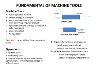
  • 1. FUNDAMENTAL OF MACHINE TOOLS Machine Tools :  Power operated machine  Expend energy to cut metal  Metal removed from blank in form of chips to develop required product  Required finish and accuracy of the part is to be maintained  Uses cutting tool  Non portable Example :- Lathe, Milling, Broaching and so many… Operations : Hold the blank. Hold cutting tools. Different types of motion-linear, rotary, combination or intermittent as needed for different parts.  Input- Information of job shape, size -work shape, size, material - energy machine tool information  Output- Required shape size accuracy -finish and integrity of surface -rate of production, mfg cost/piece input output machine tool operator feed back to operator Man machine system
  • 3. CLASSIFICATION Based on Field of Application i. General purpose: Highly flexible, wide range of work-piece Variety and material, cost effective job Production. Ex-plain turning lathe, turret lathe, milling & grinding machine etc. ii. Production purpose: Less flexible, work variety and material limited, cost effective batch and mass Production. High power and rigid. ex- multi tool lathe, plunge cut grinder etc. iii. Specialized: Same shape but different size product. Readily can be switched overfrom one job to other. Ex- iv. Single purpose: Specialized for a definite machining operation. Ex. Thread cutter, gear hobber etc. v. Special machine tool: Tool grinder, threading by die tap etc.  Based on Configuration Horizontal, Vertical, Inclined.  Based on Primary Machining Operation Turning, Milling, Grinding, Combination machine tool Based on Nature of Cutting Motion Rotating tool/Reciprocating tool According to Accuracy Normal Accuracy: Majority of components Higher Accuracy: Critical parts requiring assembly and alignments Precision: More stringent accuracy and narrow tolerance Based on Environment Heavy duty: >10kw, continuous running Medium duty: 3-10kw, medium load Small duty: <3kw, small load and minimum time of running. Based on Degree of Automation Manual-control Semi Automated- Automated-
  • 4. Major Components of Machine Tools  Components for holding tool and workpiece.  Prime mover to provide power.  Kinematic chain for transmission and transformation of power.  Structural body sufficient to support dead and live load within specified limit.  Proper control and automation systems. Specification of Machine Tools It is the parameters to express the functional requirements of the machine Tools. Generally they are_  Size limit of the work  Maximum and rated power  Spindle speed-range, no of divisions  Feed ranges  Floor space , weight etc.  So many others Types of Motion in Machining  i)Primary Motion: It serve the purpose of removing metal. It has two types. a)Principal/Cutting Motion: Depends on optimum cutting speed for tool work- piece combination and nature of machining. It may be rotary, linear or combination of both. b)Feed Motion: Depends on required finish of the product. It may be continuous, intermittent, compound.  ii)Auxiliary Motion: It help to accelerate other processes involved in production apart actual machining. This motion may be hand driven or automated. Ex- changing of speed and feed, clamping and unloading of work in the machine tool etc.
  • 5. Performance Criteria of Machine Tools  Safety  Ease of Operation: Less fatigue for operation, loading, unloading and bringing tool and w/p in engagement should be easier by automation or quick acting clamp etc.  Production Accuracy: Geometric, locational and dimensional accuracy with surface integrity as per requirement. Possible if machine tools is designed with sufficient stiffness and alignment and manufacturing accuracy of components.  Production Capacity: Max. no. work-piece per unit time would be as per required.  Reliability and Maintainability  Ease of Maintenance  Compactness: Should be high, fixed and operating cost should be as low as possible. Cost Effectiveness of Machine Tools 1 2 3 Cost Of Prdn. Rate of production 1.General purpose 2. NC Mahines 3.Special purpose machine
  • 6. General Feature of Construction of Different Parts and Working of Lathe  Oldest and important machine tools.  The principal surface developed is cylindrical surface.  Job is rotated (turned) and tool slides relative to job. So it is turning.  Cutting Speed: V=Πdn/1000 m/min; d in mm , n is rpm.  d=Depth of cut =b cos( ); is Side cutting edge angle, b=Width of cut.  f=Feed in mm/rev  But many other operations like facing, parting, taper turning and so on is performed by this machine tools.  So it is termed as “The father of machine tools family.” s  s 
  • 7. Construction of Lathe and its Components  Power Transmission: Transmitted through series of kinematic chain/mechanism_ • Simple train: Individual motion has individual power. Found in modern machine tools. • Complex train: different motion and power from single power source. • Compound train: combination of simple and complex train. A lathe is typically consist of basic components like- Headstock: It is fixed at the left end. It houses power source, power transmissions and spindle.  Power Source: • Induction having one or two fixed speed for stepped variation. • Variable speed induction motor, dc motor for stepless drive. • ac and dc servo motor, stepper motor for NC, CNC Machine.  Power of Motor: Is to be estimated to overcome power for machining, friction, inertia forces, auxiliary motion etc.
  • 8.  Spindle: • It imparts rotary motion, hold centres/work holding devices/ work/ tool as required. • It is hollow to take long bar stock. • It has an external tapered surface at the front end to locate driving plates/chucks. • Front side has taper bore to accommodate centres.  Centres: • The centre held in spindle is known as live centre having an included angle 60 degree as they rotate. • Live centre is mounted on ball bearing/tapered roller bearing along with thrust bearing. • It is also preferred during high speed machining to reduce frictional heat generation. • Centre used in tail stock is called dead centre as it does not rotate. May be of normal, half ended for turning and facing operation, spherical ball ended centre to accommodate set over. • The centre in tailstock is subjected to heavy wear due to relative velocity between centre and workpiece. Wear resistance can be increased by tipping the point with cemented carbide or wear resistant alloys.
  • 9. Tailstock: • Function is to hold dead centre which supports long work piece (l/d>4). • It is clamped on the right side of bed. • It consists of two parts. Lower part rests on bed ways and upper part rest on lower part. • Lower part along with upper one can be slide over bed through guide ways to accommodate different length as required. • Adjustable screw holds two part together. • By loosening it, upper part can be moved away or towards the operator to offset tailstock. • The body of the tail stock has a bore for hollow cylindrical sliding member known as quill. • Drills, reamers, tap and other tools are held and fed to the workpiece by the quill.
  • 10.  Carriage: • It is moveable components between head stock and tail stock. • Its prime function is to hold the cutting tool and to provide required relative motion to the cutting tool (Longitudinal feed and Cross feed). • It includes five major components like –saddle, cross slide, compound rest, tool post and apron mechanism.  Saddle: Base of carriage, slides longitudinally along the bed ways.  Cross Slide: • Mounted on saddle by means of dovetail ways. • Provide cutting tool motion in cross direction which may be controlled manually by handle or by power feed.  Compound Rest: • It has a graduated base that can be swiveled around vertical axis so that it can be angled with axis of workpiece. • So it is used for angular cut, specifically in case of short taper.
  • 11. • In order to achieve good performance of machine tolls, its supporting structure must be designed with sufficient strength and stiffness. • In order to absorb vibrations, it is made as a rigid casting part. • Deformations and stresses developed due to torsion and bending depends on size and additionally on shape. • The section providing maximum moment of inertia and sectional modulus should be selected. And hollow box type section is the best. • The top of bed is planed to form guideways. • These are the rails on which complementary part slides. • Less expensive and low duty lathe have flat ways while medium to heavy duty lathe have combination of 2 pairs of guideways to provide motion to saddle and tail stock.  Tool Post: • It is mounted over compound rest in a T- slot as shown. • It can be adjusted to tilt with the help of a concave ring collar and rocker base.  Apron: • It contains Apron Mechanism reduction of speed and rotary to linear conversion of speed. • It lies under the saddle in front side of lathe. • https://www.youtube.com/user/munmachi neshop go for setting and working.  Bed: • Bed is the base of lathe which supports all other components. • During cutting operations, majority of structures are subjected to complex loading like-combinations of torsion, bending, tension or compression which results accountable deformations leading to question on accuracy of parts.
  • 12. Speed Changing Methods: i) By Shifting Key ii) Ruppet Drive iii) Pre-Optive Drive (variable position clutch ) iv) Engaging Clutch v) By Shifting Cluster Gears. Engaging Clutch- Drive System: Mainly two types_ • Primary Cutting Motion and Feed Motion. • Primary cutting motion drive enable to achieve certain speed range and variation for spindle. • Feed motion drive enable to achieve range and variation of feed in linear motion. Primary Cutting Motion Drive/Spindle Drive: • In general geared head stock drive is designed to get stepped variation in spindle output in multiple of 2 and 3 i.e; 3,4,6,8,12,16 and 24. • As no. of variations become more, complexity of drive arises. • Variations are arranged in geometric progression with common ratio 1.06, 1.12, 1.26, 1.41, 1.58 and 2. ( as c.r increases productivity loss increases and as c.r reduces more variation and complex design). • Common ratio where z is no of step. min max 1 N N z   
  • 13. By Shifting Cluster Gears: • A set of gears which can be slide on shaft to mesh with required gear is known as slider gear or cluster gears. • Gear 1, 2 and 5,6,7 are cluster gear. • Corresponding ray diagram is shown which indicates six number of speed variation in output spindle. Some Criteria: • Fixed gears spacing must be > 2b. (b width of gears) • Minimum difference in teeth of adjacent gears in a cluster must be => 4. • Minimum no. of teeth in gears for speed box => 20. Advantage: It is more efficient and compact , able to transmit high power, available power for all types of speed remains almost same.
  • 14. Back Gears: i. For low duty smaller lathes, power transmits from motor to the cone pulley mounted on spindle by means of belt. ii. Spindle speed is changed by shifting belt to different pulley. iii. In order to get more variations and minimum speed back gears are used. iv. Cone pulleys and gear A is mounted on sleeve on spindle helps to rotate freely. v. Whenever lock pin is engaged, rpm is directly drives spindle, as gear B is rigidly mounted on spindle and N1, N2, N3 are obtained. vi. When back gears C and D are engaged with A and B respectively and lock pin E is disengaged, motion is reduced to N4, N5 and N6 with transmission ratio . i.e; N4 = N1 X B C D A Z Z Z Z   B C D A Z Z Z Z  
  • 15. Feed Box: Work at very low velocities and does not pose serious vibrational problems. There are large number of speed reduction ratio and feed steps than speed box. Rotary to linear conversion and may be continuous or intermittent. Feed drive in lathe consist of_ (a) Reversing Mechanism (b) Change Gear Quadrant (c) Quick Change Gear Box (d) Lead Screw (e) Feed Rod (f) Apron Mechanism  Reversing Mechanism: • Function is to reverse the direction of lead screw/feed rod , thereby reversing the direction of feed. • Consist of four spur gears with consecutive engagement of the bracket holding reverse gears. • Gear z2 and z3 are freely mounted on stud iii and iv of the bracket which is mounted on shaft ii. • Feed reverse lever can be moved to three positions 1,0,2.
  • 16.  Change Gear Quadrant: • It is two pair gear arrangement with a quadrant proper. • It serves to set up feed drive to different speed of lead screw and feed rod. • It is employed in cases, when it is necessary to obtain precise transmission ratio for required generating motion. • The set of change gears are chosen so that almost practically all transmission ratio can be obtained. • Z2 and Z3 are keyed on a sleeve which can be mounted freely on stud E which can be adjusted and clamped along the slot to compensate centre distance. • For the given case, gearing ratio is 4 2 3 1 z z z z  
  • 17.  Quick Change Gear Box: • The quick change gear box is located in front side below head stock. • Function is to rapid change in (a)Feed rate (b) rpm of spindle/ feed rate by shifting corresponding lever. • It contains (i) A number of different size gears (ii) Intermediate gear (iii) Tumbler gear (iv) A chart. • The tumbler gear can be slide over shaft to mesh any gear on shaft I via intermediate gear mounted on shaft II by swinging and sliding lever. • Shaft III on which tumbler gear is mounted is the driving shaft. • The number of gears in cone = number of transmission required. • Positive Features: i)Compact design to enable large number of transmission in single group. ii)Simple control by using single lever. iii)N feed rate can be found by using N+2 gears only. • Negative Features: i)Insufficient rigidity and accuracy of meshing. ii)Poor lubrication. iii)Possibility of dirt accumulation in housing.
  • 18. Specification of Lathe: 1. distance between centre. 2. swing over bed: max. dia of job that can be turned. 3. swing over cross slide: max dia of work turned with job cross slides.  Apron mechanism: • Main function is to transfer rotary to linear motion with subsequent speed reduction. • Feed rod 2 has a keyway along its whole length. • Worm 3 with its key slides along the rod. • Worm mesh with worm wheel 4 and motion transferred to pinion 5 mounted on same shaft. • By turning automatic feed knob pinion 5 meshes with gear 6 and rotation transfers to pinion 7 which runs on rack fastened to bed. • It is employed for turning and other operations. • For thread cutting, instead of feed rod lead screw take active part. By changing feed, change lever to neutral position feed rod become inoperative and Lead screw active. • Lead screw feed the carriage through two half nut mounted at the rear wall of Apron when engaged.
  • 19. Work Holding Devices Primary Functions: • To hold work-piece at suitable location by effective clamping. • Used for different machine tools. • Work holding devices in lathe- centre, chuck, collect, face plate, mandrel, steady rest, follower rest, mandrel etc. are used depending on shape, size, location of work-piece. Chucks: • Chucks are available in many style and types. • Size wise it also varies from small drill chuck to massive lathe chuck. • It have long been useful work holding devices for variety of cylindrical work. • Development of novel accessories and their implementation in standard chuck make it more useful.  Three Jaw Chuck: • 3 jaws move inward or outward simultaneously by same amount. • Jaws are 120 degree apart. • Known as self centering chuck. • Although quick centering but limited gripping force; so not suitable for heavy or precise work as accuracy 0.125 TIR( Total indicated run out) • Mechanism involve combination of bevel gear drive and a spiral rack(scroll plate). By turning the bevel pinion, scroll plate rotare and rotation of scroll plate move jaws by meshing flat teeth behind jaws with spiral rack.
  • 20.  4 Jaw Chuck: • The independence of the jaws movement. • Make this chuck suitable for holding even non-circular part, heavy part with greater clamping force and reasonably greater accuracy than 3 jaw. • Individual jaw can be moved radially over its slot by rotating individual jaw screw.  Magnetic Chuck: • Magnetic chucks is used to hold magnetic material (iron/steel). • Parts are thin and prone to damage under heavy clamping force. • Chuck is used when light cut and special grinding operations. • Chucks are fitted to an adapter mounted on spindle. • For aligning work is held lightly by turning chuck wrench a little bit. Then work is trued and chuck is turned full-on-position to hold job securely. • https://www.youtube.com/watch?v=vfhZnJWlcb4
  • 21.  Collet Chuck: • Most accurate and used for precise job. • Each collet has a range of 100ths. of mm. over or under the size marked on it. • Variety: Spring Collet Chuck & Jacob Collet Chuck. • Jacob collet has wider range of work. • Hold round, square or hexagon shape very fast. Limited to smaller job. • In the taper of head stock spindle, a special adapter is fitted. • A hollow draw bar with an internal thread is inserted in opposite end of spindle. • Rotation of hand wheel draws the collet into the tapered adapter causing a uniform pressure on collet sleeve. • Sleeve segments are elastically deflect and clamp the component. • As deflection is within elastic range, upon removal of pressure, sleeve spring back quickly, thus unloading of work is faster.
  • 22. Lathe Dog • When l/d >4, work is held between centres. • Work is rotated by driving lathe dog. • Drive plate is mounted on threaded nose on spindle. • Drive plate has one open slot and three closed slot. • A pin inserted in open slot engage tail of the dog. • Thereby impart rotation from spindle to drive plate to pin to dog to work. • Dog has opening to receive work and a set screw to fasten dog to work. • Various size and types to suit various work. • Dog available as_ • bent tail, straight tail, clamp type etc. Face Plates: • Used to hold work too large or odd shaped such that can’t be held in between centre or in chucks. • Face plates are equipped with several slots to use bolt for work holding • It may also have angle plates so that work axis may be aligned with lathe axis • When work is mounted off centre a counterbalance should be designed to prevent imbalance and resultant vibration.
  • 23. Steady Rest: • It is clamped on lathe bed at desired location. • Supports the work by three adjustable screw jaws. • Jaws should be adjusted to align the axis of work. • Top half can be swung w.r.t lower half for easy removal of work. • It is suitable for long and thin work for a support in between centre. • As the carriage can’t pass over it, the work need to be turned in two set up (left hand Portion first and then reversed to set back side in chuck or vice versa). Follower Rest: • It is mounted on carriage at the rear side so that it can follow cutting tool and thereby bear the load at machining point effectively. • It has two jaws to bear against work surface. • Used for long and very thin work for turning and thread cutting operation. • For both the cases, jaws may be provided with ball/roller bearing to reduce heat generation during high speed machining.
  • 24. TAPER TURNING Taper Specification: Out of 5 parameters (D, d, l, L, α) 3 must be given to identify it. Ways to specify (i) Inclination-(1:2x) = (ii) Half Taper Angle α = Standard Tapers: (i) Morse Taper: size 0,1,2,3,4,5,6 . Each one has definite size and definite taper angle. (ii) Metric Taper: size 4,6,80,100 etc. indicates larger diameter and all have same taper angle. Application of Tapers: Cone Clutch, Counter Shank Screw, Centre, Tool Holders etc. Method of Taper Turning: (i) By swiveling compound rest (ii) by using form tool (iii) By setting over tailstock (iv) By taper turning attachment l d D 2          l d D 2 tan 1
  • 25.  Taper Turning by Swiveling Compound Rest • Compound slide or compound rest is the component mounted over a swiveling base fixed over cross slide. • Compound slide is set in direction of lateral arc line of taper so that cutting tool follow the path of tapered surface. • Setting is done over swiveling base at half taper angle and then tool is clamped. • By rotating handle at the right the tool post is given feed along axis as there is screw nut assembly system for conversion of rotary to linear motion. • Tool is fed manually. • Advancement of tool for depth of cut is assigned by cross feed of cross slide. • The length of compound slide is limited. • The work is manufactured manually, so only short tapers are manufactured by this process. • Due to hand feed, accuracy and finish of the part is not up to the mark.
  • 26.  Taper Turning by Form Tool • Form tool is the tool which impart predetermined contour / profile to the work. • The tool is grounded to form the required angle of the taper and the tool feed is perpendicular to lathe axis. • The width of tool is slightly exceeds the length of taper. • Large no. of variety tool is required. • Suitable for short taper. • Mass production of non variable shape and size is cost effective. • Not suitable for variety of work in shape and sizes.
  • 27.  Taper Turning by Offsetting Tail Stock • In compound slide method tool traverse (feed) is parallel to the surface to be developed i.e at an angle equal to half taper angle w.r.t. lathe axis. • In form tool method tool traverse parallel to axis, work is set aligned to line of centre but cutting edge ( making an angle equal to half taper angle ) are parallel to surface to be developed. • In this case, tool traverse is parallel to lathe axis but work is set to angle to form the same angle between line of centre and feed direction. • Line of centre is set to required angle by shifting tail stock centre • When tail stock is shifted towards the operator, larger dia will be at head stock and away from operator larger dia will be at tail stock. • Set over for taper = • Set over of part length L with tapered length l will be = • Set over is obtained by setting upper part of tail stock from base by amount graduated on the scale. • Set over or offset is to be limited L/50 otherwise work may slip from tail stock centre or unbalance of work may occur. Therefore it is used for gentle taper ( <8 degree) of long length. • It develops non-uniform wear of dead centre. 2 d D  l L d D   2
  • 28.  Taper Turning by Taper Turning Attachment • Bracket is attached to lathe bed at rear side. • Bracket carries a guide bar which can be swivels against a pivot point. • The required angle = half of taper angle is set by swiveling bar and fixed the stud at correct position in the slot of bracket. • A guide block connected to lathe cross slide by tie bar. • Due to longitudinal feed of saddle, guide block will slide along bar. • As guide block is linked to cross saddle, it is moved in a direction parallel to guide bar. And the surface is cut. • Cross slide will be disconnected from saddle by removing cross feed screw/ disengaging cross slide and cross feed screw nut • After each cut, tool is given depth of cut by rotating handle of compound rest. • Tapers may be turned repeatedly without changing normal set up of machine. So, same alignment is maintained and good repeatability for the part. • Tapered holes can be bored easily. • Tapers are developed by providing longitudnal power feed. So productivity is quite high and suitable for mass production. • for less no. of job process is not cost effective.
  • 29. THREAD CUTTING Thread cutting is one of the important operation frequently performed in lathe. It may be considered as turning with some special consideration- to cut helical grove of proper form and depth. Before discussing about thread cutting it is essential to look into basic details of a thread. There are variety types of thread- square, ACME, NPT pipe thread, buttress thread etc. however, they are classified majorly as BSW (British standard whitworth) and ISO Metric thread regarding standardization. BSW- Angle 55degree, depth 0.6403xpitch Radius at crest and root- 0.17329xpitch Metric-angle 60degree, root radius- 0.0633xpitch(max) Depth =0.54127xpitch Steps in Thread Cutting_ 1) To find accurately shaped cutting tool which is accomplished by thread gauge. 2) Tool is mounted on tool post and ensure that tool top is aligned with axis of rotation 3) Establish a specific relation between longitudinal feed and spindle rotation which is performed by changing gears or corresponding chart by shifting lever in semiautomatic lathe. Driver/driven =P/L where P =Pitch of thread to be cut and L is lead of lead screw. Gears are available from 20 to 120 and special gear teeth 127. if possible simple train can be selected ,if not set compound gear train. 4) Longitudinal feed is provided by lead screw not by feed rod . Two halves of the split nut(half nut) is to be closed on lead screw and carriage moves as lead screw rotate. 5) If L= NXP(N is any integer) i.e if lead screw pitch is an exact multiple of thread pitch, thread is known as even thread otherwise odd thread.
  • 30. 6. If even thread, after the completion of tool travel, half nut is disengaged, tool is retracted and returned back to original point manually without stopping /reversing lathe. Next pass is started with specific d.o.c. (first cut .25-.4mm and gradually reduced to .027 -.075mm) 7. If odd thread, after the completion of tool travel, half nut is not disengaged, tool is retracted and returned back to original point by stopping and reversing lathe so that it follow the exact earlier path in subsequent passes. 8. Tool can be fed inward either radially or at angle half of thread angle. 9. For the first case, cutting take place along both flanks of the tool. As tool is provided with zero or negative rake, it does not initiate proper cutting. Higher cutting force, chances of chatter resulting poor finish and low tool life. Applicable for cast iron and brass. Suitable for ACME, Square thread. 10. In Second case, cutting take place on the face of the tool. Compound slide is rotated half of thread angle and cutting tool is adjusted perpendicular to surface. Cutting is favorable as chip is curled easily.
  • 31. The production rate of cutting screw threads can be increased with the use of tool called die head chaser. Tools have four cutters with multiple teeth which can be adjusted radially. For smaller diameter thread, adjustable round solid threading die is used. Proper size die is selected and held in a die holder which is placed in tail stock centre. Work-piece is held in headstock spindle, rotated slowly. The tailstock hand wheel is rotated to engage die over work piece and to cut the threads. For cutting internal threads, same procedure is followed by use of tap.
  • 32. Power requirement in turning: required power depends on speed, feed, d.o.c, tool material, work material –its hardness and machineability and nature of machining. However, for a rough estimation of power in turning is done by = cutting force cutting speed; Cutting force= Kxdxf ( d=d.o.c in mm, f is feed in mm/rev, K=constant based on work material N/mm2) Machining time calculation: Calculate N (spindle rpm)= 1000V/Πd Time for single pass= L+overtravel/F.N ( overtravel may be 2 -4 mm. either side depend on operator choice) Number of roughing pass: = (total allowance- roughing allow.)/d.o.c Number of finish pass= finish allow./ finish d.o.c Problem 1: Estimate the actual machining time required for the component of length 120mm to turn to 42mm. Available speed70,110,176,280,440,700,1100,1760, 2800. roughing speed 30mm/min and feed .24mm/rev. finish speed 60mm/min and feed .1mm/rev. finish allow. 0.75mm and blank dia 50mm. Find power required. Sol: stock to be removed (50-42)/2= 4mm for roughing-available stock=4-.75=3.25mm. Considering max d.o.c =2mm no.of pass=2 avg. dia = (50+42)/2=46mm. N= 207rpm. Take N= 176, Machinig time for roughing=2x (120+4)/(.24x176) =5.82min finishing rpm= 60x1000/πx42=440rpm machining time for finishing=124/(.1x440)=2.77 min.
  • 33. Problem 1: A taper pin of length 80mm has taper length 48mm.The larger dia 83mm and smaller dia 73mm. (i)Calculate the angle for compound rest set up. (ii) tail stock set over. Problem 2: Calculate tail stock offset for a taper of 8 degree on a job of 120mm long And larger dia 80mm. Problem 3: Calculate change gears to cut a single start thread of 0.5 mm pitch on a Centre lathe having a lead screw of 12mm pitch. Problem4. calculate the change gears to cut a single start thread of 4 tpi on a centre lathe with lead screw of 3mm pitch.
  • 34. Reciprocating Machine Tools • Machining of flat surfaces (horizontal/vertical/ inclined) by means of straight line reciprocating single point cutting tool is performed either in shaper or planning machine or slotting machines. • In case of shaping work-piece is stationary and cutting motion is provided in the cutting tool. feed motion is provided in a plane perpendicular to cutting motion. Shaping is limited to small to medium size of work-piece as stroke length is limited to 800 - 1000mm. • For planning prime cutting motion is given to the work-piece on table. Tool is moved slowly for imparting feed motion. Planning are performed for heavy and large job of heavy duty. Having a box type of configuration it is more rigid and able to take heavier cuts. • Slotter works on same principle as shaper but tool travels in vertical plane. Slotter is provided with indexable rotary table about vertical axis. Table moves on saddle. Rotary along with two straight line motion of table enhances its capability on working range. It is widely used for machining blind holes, splines, keyways etc. machining of straight and curved die can also be machined.
  • 35. SHAPER  Base: Provide support, carry dead weight and dynamic load. Generally grey cast iron,  Housing: Hollow casting, mounted on base. Houses drive mechanism for ram movement and table. Top of housing are arranged with guide ways for smooth motion of ram.  Table: Fastened at the front of housing, table is moved across the housing on cross rail for feeding. It can also be moved up and down on housing to accommodate different size of work- piece by elevating screw.  Ram: It carries the tool head at front and travels in guide to provide straight motion to the tool. Based on the nature of drive- mechanical/hydraulic , shaper is classified.
  • 36.  Tool Head: It is connected to front of ram and hold the cutting tool via tool holder on other side. The tool post and tool block have snug fit in the clapper box and hinged at upper edge. During forward stroke, the tool block is solidly supported against clapper box due to cutting force. During return stroke, tool block is free to swing forward from pivot. This lift up the tool to avoid rubbing against machined surface. Tool head has a feed screw rotated by handle for raising or lowering the tool to adjust d.o.c. the slide is rotated on swivel plate which enable tool head to be rotated to take angular cuts. While machining inclined surface, clapper box must be swung along an arc away the work-piece surface.
  • 37. • Nature of tool geometry develops triangular hill valley profile on machined surface based on tool geometry and operating parameters. • The height from valley to hill can be reduced by decreasing feed/stroke which reduces MRR. • Another option is to use broad nose tool with high feed/stroke but causes unavoidable vibrational problem. Flat Surface Generation
  • 38. Quick Return Mechanism • Bull gear is driven by motor via bull gear pinion. • A pin fits freely into a hole in bull gear block holds a sliding block which slides in the slot of rocker arm. • The rocker arm is pivoted at lower end of column and upper end is connected by a link to ram block which is secured to ram. • Ram stroke is adjusted by changing crank radius on bull gear. • If radius is increased stroke length will be more and vice versa. • Another option is to change the distance between pivot point of slotted arm and centre of bull gear.
  • 39. • From the angle α and β, it is realized that the return stroke takes less time. • Average cutting speed= L/t(cutting) • T(cutting)= (1/N)X(α/α+β)min. • Avg. cutting speed=L.N.(α+β)/α=L.N(1+(1/r)) where r= α/β>1 and kept 1.5 • Average return speed= L/t(non-cutting) • T (non cutting)=(1/N) X (β/ α+β) min. • Avg. return speed =L.N.(α+β/β)=L.N.(1+r) • The speed mentioned for any particular stroke is not uniform, rather it is varying followed by the shown curve. • As there is a wide variation of load w.r.t time, so for getting a smooth and Jerk- free movement of ram, a flywheel is essential. • Big bull gear function as well as a flywheel. • Stroke length is adjusted such that tool starts cutting stroke a small distance before the w/p is engaged by 10 to 20mm and complete the stroke 10-20mm. • After disengage with w/p.
  • 40. • Feed is intermittent and provided only during return stroke. • The feed is given through feed screw rotated by a ratchet wheel. • The ratchet wheel has intermittent rotary motion by engaging with spring loaded reversible pawl. • The pawl gets it motion from a slotted disc through a connecting rod. • The slotted disc is rotated at same speed of bull gear through a intermediate spur gear. • As the pawl is straight on one side and slanted on the other, it rotates the ratchet in one direction when pawl teeth pushes ratchet. • When pawl teeth is pulled by connecting rod it slides over ratchet teeth and no rotary motion is imparted. • Pawl is spring loaded to keep contact with ratchet wheel. • By rotating the knob at the top by 180 degree feed direction can be reversed and by rotating 90 degree feed may be zero. • The rate of feed is controlled by adjusting the eccentricity of driving pin in slotted disc. Feed Mechanism in Shaper
  • 41. Hydraulic Shaper • A constant speed motor runs a pump which delivers oil at constant pressure in the line. • Through flow control valve to 4 way regulating valve. It admits oil under pressure to each end on the piston alternately and allowing oil from opposite end to return to reservoir. • The flow of oil in each end is accomplished with the help of trip dogs and pilot valve. • As ram completes it stroke, trip dog will trip the pilot valve which operate 4 way regulating valve to alter the direction flow of oil. • Stroke length is adjusted by using trip dogs at desired location. The speed of ram is proportional to oil pressure and area of piston. Advantage: a) Cutting speed remains constant during cutting and return speed remains constant during return stroke. b) Ram reverses quickly without experiencing any shock as inertia of the working parts is comparatively small. c) Range and number of cutting speed are large. d) More stroke/min is possible. e) Ability to change length and position of stroke. Disadvantage: Initial cost and maintenance cost too high.
  • 42. Numerical problems 1. Calculate the rpm of the bull gear of a mechanical shaper if cutting speed is 35m/min. with adjusted stroke length 250mm. Assume ratio of cutting stroke to idle stroke as 1.5. Solution: let rpm of bull gear be N. So, for 1 rev. time needed is 1/N min. Out of this 1/N min, cutting time is (15/25)x(1/N) min. Dist. Travelled=(35m/min)x(15/25)x(1/N)min=250/1000 N=(35X15X1000)/(250X25)=84 RPM. 2. A part measuring 300mmx100mmx40mm is to be machined using hydraulic shaper along its wide face. calculate the machining time taking approach and overtravel as 25mm each. take cutting speed as 15m/min and machining allowance on either side of plate width is 5mm and feed is 0.4mm/stroke. Solution: =300+25+25=350mm No. of stroke required= (100+5+5)/0.4 =275 Being hydraulic shaper, cutting speed i.e assumed uniform speed in a stroke =15000mm/min. Time required for machining= ((350x2)/15000)x275=12.83 min. 3. A shaper is operated at 2 cutting stroke per second and is used to machine a work-piece of 150mm length at a cutting speed of 0.5m/s using a feed of 0.4 mm/stroke and a depth of cut of 6mm. (a) calculate the total machining time to produce 800 components each 100 mm width. (b) if forward stroke is over 230degree, calculate % of time when tool is not contacting work. Solution: No. of stroke required= (100+5+5)/0.4=275 Machining time/piece needed=(275/2) s Total machining time = ((275/2)x800)/3600 hr=30hrs. cutting time for a stroke= α/(α+β)N=230/(360X120)=.0053min Idle time for a stroke =β/(α+β)N=130 /(360x120)=.003 min % of time tool not contacting work= (.003/.0083)x100= 37.5% a o eff L L L L   
  • 43. HOLE MAKING OPERATIONS Different type of holes are Through hole, Blind hole, Counter bore , Counter sink, Step hole etc. Operations Include_ Drilling: Making a drill with the help of twisted drill. Core Drilling: Uses core drill to enlarge and improve geometric shape. Reaming: Uses reamer to get accurate size and finish of previously drilled hole. Counter Boring: Uses counter bore to enlarge certain portion of drilled hole, sometimes needed for setting of screw head or bolt head. Counter Sink: Chamfering of entrance of drilled hole for setting flat head screw or rivet. The angle may be 60/82/90 degree. Step Drilling: Uses step drill i.e. combination of drill bit of two different diameter.
  • 45.
  • 46.
  • 47. Drive in Drilling Machine Main Drive: From motor, motion goes to spindle by a pair of cone pulley –v belt drive. In order to get different speed, it can be designed with change gears. Feed Drive: • The spindle has a keyway or spline so that it may be moved up and down retaining its drive at fixed point. • There is a non-revolving quill or sleeve in which spindle freely rotate. • Drill sleeve carries a rack which meshes with pinion. • Pinion is turned by hand lever in small machine or by automatic transmission by designing gear change drive with main drive. • So, main objective is to get a calculated rpm of pinion for a desired feed. • Drill sleeve is moved up and down along axis. • Spindle is held with upper end of sleeve by two ring nut and with lower end of sleeve by collar of spindle head. • To reduce friction, ball bearing arrangement is provided between sleeve and collar.
  • 48. DRILL BIT  SHANK: the part of the bit used for mounting on spindle or other operating elements to transmit motion and power to the cutting tool. • For drill bit up to 13 mm. dia have straight shank and are held in drill chuck • For dia >13 mm. tapered shank bit is used. Taper shank fits into internal taper of spindle. At the end of shank, tang is provided to prevent slip during operation and to allow the drill to be removed from spindle without damaging shank.  BODY: It is the part in between shank and point. It consists of certain elements like Flutes: Two or more helical grooves which form cutting edges are cut around the body. They allow cutting fluid to reach at machining point and allow the chips to escape. Margin: Narrow raised section next to flute and extends along entire length. Its purpose is to provide full size of drill body and cutting edges. Drill bit i.e. Twist drill is used as cutting tool for drilling. Other special type of drill bit are also in use for drilling special type of holes. Drill bit Material: General material is plain c-steel/h.s.s. for drilling hard and brittle material. Drill bit with carbide tip increase productivity by 30% over h.s.s. CONSTRUCTION: Main parts are_ i) Shank ii) Body iii) Point Body Clearance : Undercut portion of the body between margin and flutes. It reduces friction between drill bit and surface of drilled hole. Web: Thin portion in centre of drill along entire length. It gradually increases towards shank. It is the strength of the drill bit and it form chisel edges. Dia of drill body is reduced towards shank to avoid rubbing along whole length.
  • 49. Chisel Edge: • Chisel shaped portion at the centre of drill point. • It is formed by intersection of two flanks. • This part does not cut material but pushes material out of centre of the hole in front of cutting edges. Lip: • Lips are formed by intersection of flutes. • They must be of equal length, equal angle and sharpness in order to drill turn true. Otherwise hole will be oversized, eccentric and excessive wear of tool. Rake Angle: • Axial rake angle is the angle between the face and line parallel to axis. • This angle changes based on position on face. • It is equal to helix angle at the periphery. • It is complex angle which depends on helix angle, point angle and feed rate.  POINT: This is the prime component which actually take part in cutting. The shape of point is very important. It consists of basically chisel edge and heel. Helix Angle: It is the angle formed by leading edge of land to the axis. The angle helps to escape chips clearly. Lip Clearance Angle: From cutting lip to back of heel a relief is provided. This is known as lip clearance angle. Lip/Point Angle: To determine shape of point. General value118 degree. Larger for hard and brittle material.
  • 50. DEEP HOLE DRILLING Deep hole means L/D >5 Problems encountered in deep hole drilling are- • Hole tends to run off • Less rigidity of tool • Large elastic deformation • Excess play in bearing • Non-uniform adhering of chips on lips and non uniform length of both lips • Guiding actions of margins • Supply of coolant • Removal of chips Operating Parameters for Deep Hole Drilling 𝑉𝑑𝑒𝑒𝑝 = 𝑉𝑑𝑟𝑖𝑙𝑙 1 − 𝑑𝑒𝑝𝑡ℎ 𝑜𝑓 ℎ𝑜𝑙𝑒 40𝑥 𝑑𝑖𝑎 𝑜𝑓 ℎ𝑜𝑙𝑒 𝑓𝑑𝑒𝑒𝑝 = 𝑓𝑑𝑟𝑖𝑙𝑙 1 − 𝑑𝑒𝑝𝑡ℎ 𝑜𝑓 ℎ𝑜𝑙𝑒 50𝑥𝑑𝑖𝑎 𝑜𝑓 ℎ𝑜𝑙𝑒 Prevention: • Low feed, sharepening of both lips should proper and error free • Sufficient supply of cutting fluid • Drill must be guided by jig bushing • w/p rotate, tool either stationery or rotate in opposite direction • By using special drill-half round drill/ gun drill Half Round Drill: • Single lip, more bearing surface. • Drill is taper to reduce friction and more chip clearance area. Gun Drill: • More bearing surface covering 250-300 degree. • Zig-zag designed lips for chip breaking.
  • 51. REAMING Reaming: It is hole finishing operation. Very little amount of material is cut smoothly to get better finish- parallelism, roundness and accuracy in size. • It uses multipoint cutting tool: Reamer. • It has three main parts: shank, neck and fluted portion. Chamfered Portion: l1 ensures easy entry to the hole. Starting Taper: l2 provide prime cutting action. Sizing Section: l3 guides the reamer and help in sizing the hole. Back Taper: l4 provided to minimize friction. Types of Reamer: • Hand Reamer: operated by tap wrench. Have long cutting edges. May have pilot for guiding. Have straight shank • Machine Reamer: Taper shank. Shorter cutting edge. • Solid Reamer: One piece integrated material • Shell Type Reamer: Cutting portion are made like a shell and mounted on shank to reduce cost. Siutable for larger dia. • Floating: Holders are not rigid and permit to follow previously drilled hole easily.  Left hand and Right hand  Straight flute and helical flute
  • 52. Size of Drill Press 1. swing-2x(distance from nearest face of column to centre of spindle) 2. maximum dia of drill bit that can be used on steel work-piece 3. maximum distance between spindle and table i.e maximum height of job with table in its lowest position 4. spindle up and down movement (length of feed) Machining Time: Machining time = t(m)= L/(SXN) L= length of hole + 0.3x dia of drill S=feed/rev. N=no.of rev/min. MRR=ΠDDSN/4 Torque acting on drill=𝑀 = 𝐶𝐷1.9 𝑆.8 Thrust acting on drill=𝑇 = 𝐾𝐷𝑆.7 HW: A hole of 25mm dia and 35 mm depth is to be drilled on m.s plate. Cutting speed 35mm/min and feed 0.2 mm/rev. calculate machining time, MRR, torque and thrust acting on drill. Assume setting time as 2 min. torque and thrust constant as 616 and 84.7. • Estimate machining time to cut 4 no. drill hole of dia14mm on 12mm thick m.s plate considering cutting speed 22m/min and feed 0.2 mm/rev. assume setting time=8min, auxiliary time/hole=1 min. assume available spindle speed 510. L= 12+(.3X14)= 16.2mm. ΠDN=22000 or N= 22000/(3.14X14)=500 T(actual machining)/hole=16.2/(.2x510)=.16 min. Total actual machining time= 4x.16=6.4 min. Auxiliary time= 4min. Setting time= 8 min. TOTAL MACHINING TIME=18.4 min.
  • 53. MILLING It is a machining process in which a work-piece is fed into a rotating milling cutter, a multipoint cutting tool by producing number of chips in one revolution of cutter.  Peripheral Milling: • Finished surface is parallel to axis of cutter • Machined by cutter teeth located on periphery  Face Milling: • Finished surface is perpendicular to axis of cutter • Machined by teeth on periphery and flat end of cutter. Features of Milling: • Interrupted Cutting: teeth gets time to be cooled, hence allow larger MRR • Small Size of Chip: Small but large number of chips are produced. Component can be machined in single pass. • Variation of Chip Thickness: Chip thickness Varies from engagement of teeth to disengagement with work. So, there is a cyclic variation of cutting force which may induce unwanted vibration in the system.
  • 54.  Knee and Column Type: Column: Rigid, contain SGB, Gear train. Knee: Contain feed mechanism, support saddle and table. Table has T-slot along x axis for movement in x direction, saddle moves perpendicular to x i.e. y direction. Knee can be moved up and down on dovetail ways on column face manually. Spindle: Located at top of column, hardened collar are fitted on spindle at one end and supported at other end in bearing houses in overarm. Milling cutter are fitted on arbor at desired location. Arbor is clamped in spindle by draw bar and fixed by nut. Overarm: To provide support to the arbor from other end. Vertical: Suitable for shank mounted milling cutters like end mill. Cutter may be swiveled . More flexible than horizontal. Suitable for making complex die cavities. Universal: Table can be swiveled in horizontal plane about 45 degree in each direction. Suitable for manufacturing of spur, helical and worm gear and complex cam profile. Types of Milling Machine: 1. Knee and Column Type---(a) Horizontal (ii) Vertical (iii) Universal (iv) Turret Type 2. Production (Bed) Type---(i) Simplex (ii) Duplex (iii) Triplex 3. Special Type---(i) Rotary table (ii) Copy Milling Machine (iii) Keyway Milling Machine etc.
  • 55. Plain Milling Cutter: Straight/helical teeth. Straight teeth enters the work simultaneously the whole width leading to intermittent load acting on m/c resulting impaired surface quality. Helical teeth engages progressively resulting smooth operation and better surface. Job width<cutter width, it is called slab cutter. Face Milling Cutter: Cutting edges on periphery and face also. Machine flat surface perpendicular to axis of rotation. Rigidly mounted on nose of spindle, highly productive for flat surface. Leaves feed mark on machined surface. Profile Milling Cutter: End Mill Cutter: Cutting edge on end surface radially and periphery like face mill. Shank mounted. Slot drill-teeth at end terminated at centre, so able to cut solid material. Ball bed mill- the end portion is shaped in spherical shape. Milling Cutters: (a) Construction—(i) Solid (ii) Inserted tooth (b) Mounting—(i) Arbor (ii) Shank (c) Rotation –(i) RH- C.C.W –viewed towards spindle (ii) LH -CW (d) Helix—(i) RH-flutes move in CW viewed from end (ii) LH (e) Operation—(i)Plain /Slab Milling Cutter (ii) Face Milling Cutter (iii) Profile Milling Cutter (iv) End Milling Cutter
  • 56.
  • 57.
  • 58. Dividing Head and Indexing Dividing Head: • Important attachment as work holding device and rotate the blank by exact amount for each groove to cut. • This method is known as Indexing. • Function is to cut/ slay/ groove equally spaced around circumference of blank. • Used to manufacture gear, reamer, ratchet, spline etc. Construction: It has head stock, spindle and tailstock. The assembly is bolted to machine table such that axis of spindle is at right angle to spindle of machine. The spindle of assembly is keyed to 40 teeth worm wheel and a single threaded worm meshes with wheel. One end of worm shaft has crank that can be turned manually over predetermined hole gap in selected index plate mounted on sleeve of worm shaft.
  • 59. Method of Indexing A: Direct Indexing: Index plate is directly mounted on dividing head spindle. Use of worm and worm wheel is avoided Most rapid but fraction of turn is limited. B: Simple Indexing: Available index plate in Brown & Sharpe m/c as Plate1: 15,16,17,18,19,20 Plate2: 21,23,27,29,31,33 Plate3:37,39,41,43,47,49 1/40 turn of work need 1 turn of index crank Z turn of work need 40/Z turn of index crank. Indexing for 62 Divisions----- Z=62 No. of turn in index plate is 40/62 =20/31 Crank should be turned 20 hole position of plate 2 having 31 concentric hole. C: Angular Indexing: 9 degree rot Of work need 1 turn of index crank. ϴ degree rot of work need ϴ/9 turn of index crank. Make necessary calculation for for 16 degree 40 min. Compound Indexing: It is achieved in two stages by using two different hole circle of same index plate. (i) Follow simple indexing like n holes on N hole circle and then engage lock pin in N1 hole circle. (ii) Rotate crank and index plate in same or opposite direction n1 hole in N1 hole circle by disengaging locking pin. So, (n/N) +( n1/N1)= 40/Z if both turn forward (n/N) -( n1/N1)= 40/Z if both turn opposite Indexing for 141 Divisions: 141=47X3 Plate no 3 has 47 hole and 39 also. n/39+-n1/47=40/141=13x40/39x47 47n+-39n1=520 By trial and error find n and n1 And it is found to be 26 and 18