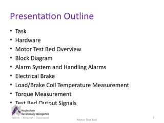
SlideShare a Scribd company logo
PLC Based Control of a Motor
Test Bed and Torque
Measurement
1
Master Thesis Presented by:
Hizbullah Khan (23559)
Supervisors:
Dr.-Ing., Professor Bernd Altmann
Dr.-Ing., Professor Franz Brümmer
Presentation Outline
• Task
• Hardware
• Motor Test Bed Overview
• Block Diagram
• Alarm System and Handling Alarms
• Electrical Brake
• Load/Brake Coil Temperature Measurement
• Torque Measurement
• Test Bed Output Signals
Motor Test Bed
2
Task
• Temperature measurement of the load coil
• Torque measurement via different methods
• Torque comparison
• Different alarm conditions
• Study sensors and modules output
Motor Test Bed
3
Motor Test Bed Hardware
• Eaton XC-CPU 101 Modular PLC (Easy Soft CoDeSys v2.3.5)
• 3 Phase Induction Motor (2 pole pairs)
• Electrical Brake (Eddy current principle)
• Frequency Inverter
• Torque Sensor (2.5± 2)V measures Toque upto 7.1 N.m.
• Tachogenerator (±2.85V)
• Voltage Transducers
• Current Transducers
• Current Monitor
• Analogue Indicators
Motor Test Bed
4
Motor Test
Bed Overview
5
Block Diagram
Motor Test Bed
6
Motor Test Bed Alarms
Motor Test Bed
7
• Three predefined alarm conditions
1. Inverter Power Off Alarm
2. Cover Lock Failure Alarm
3. Load Temperature Exceed Alarm
Handling Alarms
Motor Test Bed
8
• Acknowledging the alarm before the failure is
sorted out (timing diagram)
Handling Alarms
Motor Test Bed
9
• Acknowledging the alarm after the failure is
sorted out (timing diagram)
Handling Alarms
Motor Test Bed
10
• Acknowledging the load temperature exceed
alarm (timing diagram)
Electrical Brake
• Electrical brake works on eddy current
principle
• A non ferromagnetic metal disc is placed in between the
coils of the brake. Once the current starts flowing through
the coil and the metal disc is rotating in between the coils,
this movement of the disc changes the magnetic flux of
the coils and creates eddy currents in the disk.
• These eddy current creates an opposing magnetic field
to that of the coils magnetic field and provides the
braking force by resisting the rotation. (Lenz’s Law)
Motor Test Bed
11
Electrical Brake Coil Temperature Measurement
• Current flow of up to 3.6 A through the brake coil
• The resistance of the coil is directly proportional to heat produced in the coil
• Measuring the temperature of the copper coil
Rearranging:
Motor Test Bed
12
[1 ( )]
R R T T
coil amb coil amb

  
24.31 236.73
T R
coil coil
 
 
,
. . 0. ,
( . . 0.00 0 / ),
R Current resistance of the coil of the brake
coil
R Resistance of the coil at ambient temperature i e 1 6 Ohms
amb
Temperature coefficient of copper i e 4 41 C
T Current temperature of
coil






,
(21 )
the coil of the brake
T Ambient temperature C
amb 

Electrical
Brake
Interface
13
24.31 236.73
T R
coil coil
 
can be found using
Ohm’s law
Rcoil
Current Transducer i/p Scaling
Motor Test Bed
14
0 2 4 6 8 10 12
0
500
1000
1500
2000
2500
3000
3500
4000
4500
(0, 0)
(5, 2047)
(10, 4095)
U_CT
D_in
0 500 1000 1500 2000 2500 3000 3500 4000 4500
0
1
2
3
4
5
6
(0, 0)
(4095, 5)
D_in
Current flowing
via brake (A)
0.00122
brake in
I D

Signal Adopter i/p Scaling
Motor Test Bed
15
0 2 4 6 8 10 12
0
500
1000
1500
2000
2500
3000
3500
4000
4500
(0, 0)
(5, 2047)
(10, 4095)
U_SA
D_in
0.01075
brake in
U D

0 500 1000 1500 2000 2500 3000 3500 4000 4500
0
5
10
15
20
25
30
35
40
45
(0, 0)
(40, 4095)
D
Voltage provided
to the brake (V)
Current Transducer Block Diagram
Motor Test Bed
16
• Configurable Module via DIP switches
• Output Voltage: 0…10V, 2…10V, -10…10V, 0…5V, 1…5V, -5…5V,
• Output Current: 0…20mA, 4…20mA
Current Transducer Output
17
Programming Flow
Diagram
• CT problem
Compensated in
programming
18
Torque Measurement
• Torque sensor
• Predesigned mechanical setup
• Optical sensors and counters (Hooke’s Law
principal)
Motor Test Bed
19
Torque Comparison
Motor Test Bed
20
0 10 20 30 40 50 60 70 80 90 100 110 120
0
0,1
0,2
0,3
0,4
0,5
0,6
0,7
0,8
0,9
1
Torque Sensor
Torque (Mechanical Display)
Field Frequency (Hz)
Torque (N.m.)
Test Bed Output Signals
Motor Test Bed
21
• Tachogenerator Signal without low pass filter (CW rotation)
Test Bed Output Signals
Motor Test Bed
22
• Tachogenerator Signal with low pass filter (CW rotation)
Test Bed Output Signals
Motor Test Bed
23
• Tachogenerator Signal with low pass filter (CCW rotation)
Test Bed Output Signals
Motor Test Bed
24
• Torque Sensor Signal with low pass filter (Motor Stopped)
Test Bed Output Signals
Motor Test Bed
25
• Torque Sensor Signal with low pass filter (Torque present, CW rotation)
Measuring a torque of 0.8549, (0.28073 ) 2.5
TS
U T
  
.
Thank you
Questions, Comments ?
26
Motor Test Bed

More Related Content

Similar to Motortest_Final Presentation.pdf

nestraining-EE-EE Training Autom .ppt
nestraining-EE-EE Training Autom .pptnestraining-EE-EE Training Autom .ppt
nestraining-EE-EE Training Autom .pptpramodkommanaboina
 
Noida Metro Rail Corporation
Noida Metro Rail CorporationNoida Metro Rail Corporation
Noida Metro Rail CorporationAnkit Chaudhary
 
Design and implementation of cyclo converter for high frequency applications
Design and implementation of cyclo converter for high frequency applicationsDesign and implementation of cyclo converter for high frequency applications
Design and implementation of cyclo converter for high frequency applicationscuashok07
 
emmanuel and catherine project.pptx
emmanuel and catherine project.pptxemmanuel and catherine project.pptx
emmanuel and catherine project.pptxSungaleliYuen
 
Catalog biến tần trung thế Fuji Electric
Catalog biến tần trung thế Fuji ElectricCatalog biến tần trung thế Fuji Electric
Catalog biến tần trung thế Fuji ElectricCTY TNHH HẠO PHƯƠNG
 
Synchmachine-1.ppt
Synchmachine-1.pptSynchmachine-1.ppt
Synchmachine-1.pptdeepaMS4
 
Applying Stepper Motors: Application Questions You Must Answer & Things to Wa...
Applying Stepper Motors: Application Questions You Must Answer & Things to Wa...Applying Stepper Motors: Application Questions You Must Answer & Things to Wa...
Applying Stepper Motors: Application Questions You Must Answer & Things to Wa...Design World
 
Flyback Converter using PWM IC(LTspice Version)
Flyback Converter using PWM IC(LTspice Version)Flyback Converter using PWM IC(LTspice Version)
Flyback Converter using PWM IC(LTspice Version)Tsuyoshi Horigome
 
PARAMETER IDENTIFICATION AND MODELLING OF SEPARATELY EXCITED DC MOTOR
PARAMETER IDENTIFICATION AND MODELLING OF SEPARATELY EXCITED DC MOTOR PARAMETER IDENTIFICATION AND MODELLING OF SEPARATELY EXCITED DC MOTOR
PARAMETER IDENTIFICATION AND MODELLING OF SEPARATELY EXCITED DC MOTOR ijiert bestjournal
 
Experimental results of vector control for an asynchronous machine
Experimental results of vector control for an asynchronous machineExperimental results of vector control for an asynchronous machine
Experimental results of vector control for an asynchronous machineTELKOMNIKA JOURNAL
 
EEP301: Transducer and instrumentation
EEP301: Transducer and instrumentationEEP301: Transducer and instrumentation
EEP301: Transducer and instrumentationUmang Gupta
 
Power transformers rating
Power transformers ratingPower transformers rating
Power transformers ratingLeonardo ENERGY
 
Synchmachi.ppt
Synchmachi.pptSynchmachi.ppt
Synchmachi.pptAskUdaipur
 
Modeling and simulation of pmsm
Modeling and simulation of pmsmModeling and simulation of pmsm
Modeling and simulation of pmsmRavi teja Damerla
 
engineering and utilities report
engineering and utilities reportengineering and utilities report
engineering and utilities reportHassan Bilal
 

Similar to Motortest_Final Presentation.pdf (20)

nestraining-EE-EE Training Autom .ppt
nestraining-EE-EE Training Autom .pptnestraining-EE-EE Training Autom .ppt
nestraining-EE-EE Training Autom .ppt
 
Snap on training
Snap on   trainingSnap on   training
Snap on training
 
Noida Metro Rail Corporation
Noida Metro Rail CorporationNoida Metro Rail Corporation
Noida Metro Rail Corporation
 
Design and implementation of cyclo converter for high frequency applications
Design and implementation of cyclo converter for high frequency applicationsDesign and implementation of cyclo converter for high frequency applications
Design and implementation of cyclo converter for high frequency applications
 
emmanuel and catherine project.pptx
emmanuel and catherine project.pptxemmanuel and catherine project.pptx
emmanuel and catherine project.pptx
 
Catalog biến tần trung thế Fuji Electric
Catalog biến tần trung thế Fuji ElectricCatalog biến tần trung thế Fuji Electric
Catalog biến tần trung thế Fuji Electric
 
Synchmachine-1.ppt
Synchmachine-1.pptSynchmachine-1.ppt
Synchmachine-1.ppt
 
Synchmachine-1.ppt
Synchmachine-1.pptSynchmachine-1.ppt
Synchmachine-1.ppt
 
Applying Stepper Motors: Application Questions You Must Answer & Things to Wa...
Applying Stepper Motors: Application Questions You Must Answer & Things to Wa...Applying Stepper Motors: Application Questions You Must Answer & Things to Wa...
Applying Stepper Motors: Application Questions You Must Answer & Things to Wa...
 
Flyback Converter using PWM IC(LTspice Version)
Flyback Converter using PWM IC(LTspice Version)Flyback Converter using PWM IC(LTspice Version)
Flyback Converter using PWM IC(LTspice Version)
 
Induction machines
Induction machinesInduction machines
Induction machines
 
PARAMETER IDENTIFICATION AND MODELLING OF SEPARATELY EXCITED DC MOTOR
PARAMETER IDENTIFICATION AND MODELLING OF SEPARATELY EXCITED DC MOTOR PARAMETER IDENTIFICATION AND MODELLING OF SEPARATELY EXCITED DC MOTOR
PARAMETER IDENTIFICATION AND MODELLING OF SEPARATELY EXCITED DC MOTOR
 
Experimental results of vector control for an asynchronous machine
Experimental results of vector control for an asynchronous machineExperimental results of vector control for an asynchronous machine
Experimental results of vector control for an asynchronous machine
 
Experiment 2 AC Machines
Experiment 2 AC MachinesExperiment 2 AC Machines
Experiment 2 AC Machines
 
Dc machine practical
Dc machine practical Dc machine practical
Dc machine practical
 
EEP301: Transducer and instrumentation
EEP301: Transducer and instrumentationEEP301: Transducer and instrumentation
EEP301: Transducer and instrumentation
 
Power transformers rating
Power transformers ratingPower transformers rating
Power transformers rating
 
Synchmachi.ppt
Synchmachi.pptSynchmachi.ppt
Synchmachi.ppt
 
Modeling and simulation of pmsm
Modeling and simulation of pmsmModeling and simulation of pmsm
Modeling and simulation of pmsm
 
engineering and utilities report
engineering and utilities reportengineering and utilities report
engineering and utilities report
 

Recently uploaded

Pharmacy management system project report..pdf
Pharmacy management system project report..pdfPharmacy management system project report..pdf
Pharmacy management system project report..pdfKamal Acharya
 
2024 DevOps Pro Europe - Growing at the edge
2024 DevOps Pro Europe - Growing at the edge2024 DevOps Pro Europe - Growing at the edge
2024 DevOps Pro Europe - Growing at the edgePaco Orozco
 
Automobile Management System Project Report.pdf
Automobile Management System Project Report.pdfAutomobile Management System Project Report.pdf
Automobile Management System Project Report.pdfKamal Acharya
 
Architectural Portfolio Sean Lockwood
Architectural Portfolio Sean LockwoodArchitectural Portfolio Sean Lockwood
Architectural Portfolio Sean Lockwoodseandesed
 
RESORT MANAGEMENT AND RESERVATION SYSTEM PROJECT REPORT.pdf
RESORT MANAGEMENT AND RESERVATION SYSTEM PROJECT REPORT.pdfRESORT MANAGEMENT AND RESERVATION SYSTEM PROJECT REPORT.pdf
RESORT MANAGEMENT AND RESERVATION SYSTEM PROJECT REPORT.pdfKamal Acharya
 
Hall booking system project report .pdf
Hall booking system project report  .pdfHall booking system project report  .pdf
Hall booking system project report .pdfKamal Acharya
 
The Benefits and Techniques of Trenchless Pipe Repair.pdf
The Benefits and Techniques of Trenchless Pipe Repair.pdfThe Benefits and Techniques of Trenchless Pipe Repair.pdf
The Benefits and Techniques of Trenchless Pipe Repair.pdfPipe Restoration Solutions
 
HYDROPOWER - Hydroelectric power generation
HYDROPOWER - Hydroelectric power generationHYDROPOWER - Hydroelectric power generation
HYDROPOWER - Hydroelectric power generationRobbie Edward Sayers
 
Fruit shop management system project report.pdf
Fruit shop management system project report.pdfFruit shop management system project report.pdf
Fruit shop management system project report.pdfKamal Acharya
 
ENERGY STORAGE DEVICES INTRODUCTION UNIT-I
ENERGY STORAGE DEVICES  INTRODUCTION UNIT-IENERGY STORAGE DEVICES  INTRODUCTION UNIT-I
ENERGY STORAGE DEVICES INTRODUCTION UNIT-IVigneshvaranMech
 
KIT-601 Lecture Notes-UNIT-4.pdf Frequent Itemsets and Clustering
KIT-601 Lecture Notes-UNIT-4.pdf Frequent Itemsets and ClusteringKIT-601 Lecture Notes-UNIT-4.pdf Frequent Itemsets and Clustering
KIT-601 Lecture Notes-UNIT-4.pdf Frequent Itemsets and ClusteringDr. Radhey Shyam
 
Laundry management system project report.pdf
Laundry management system project report.pdfLaundry management system project report.pdf
Laundry management system project report.pdfKamal Acharya
 
Immunizing Image Classifiers Against Localized Adversary Attacks
Immunizing Image Classifiers Against Localized Adversary AttacksImmunizing Image Classifiers Against Localized Adversary Attacks
Immunizing Image Classifiers Against Localized Adversary Attacksgerogepatton
 
Cloud-Computing_CSE311_Computer-Networking CSE GUB BD - Shahidul.pptx
Cloud-Computing_CSE311_Computer-Networking CSE GUB BD - Shahidul.pptxCloud-Computing_CSE311_Computer-Networking CSE GUB BD - Shahidul.pptx
Cloud-Computing_CSE311_Computer-Networking CSE GUB BD - Shahidul.pptxMd. Shahidul Islam Prodhan
 
Quality defects in TMT Bars, Possible causes and Potential Solutions.
Quality defects in TMT Bars, Possible causes and Potential Solutions.Quality defects in TMT Bars, Possible causes and Potential Solutions.
Quality defects in TMT Bars, Possible causes and Potential Solutions.PrashantGoswami42
 
Online blood donation management system project.pdf
Online blood donation management system project.pdfOnline blood donation management system project.pdf
Online blood donation management system project.pdfKamal Acharya
 
Event Management System Vb Net Project Report.pdf
Event Management System Vb Net  Project Report.pdfEvent Management System Vb Net  Project Report.pdf
Event Management System Vb Net Project Report.pdfKamal Acharya
 
KIT-601 Lecture Notes-UNIT-3.pdf Mining Data Stream
KIT-601 Lecture Notes-UNIT-3.pdf Mining Data StreamKIT-601 Lecture Notes-UNIT-3.pdf Mining Data Stream
KIT-601 Lecture Notes-UNIT-3.pdf Mining Data StreamDr. Radhey Shyam
 
WATER CRISIS and its solutions-pptx 1234
WATER CRISIS and its solutions-pptx 1234WATER CRISIS and its solutions-pptx 1234
WATER CRISIS and its solutions-pptx 1234AafreenAbuthahir2
 

Recently uploaded (20)

Pharmacy management system project report..pdf
Pharmacy management system project report..pdfPharmacy management system project report..pdf
Pharmacy management system project report..pdf
 
2024 DevOps Pro Europe - Growing at the edge
2024 DevOps Pro Europe - Growing at the edge2024 DevOps Pro Europe - Growing at the edge
2024 DevOps Pro Europe - Growing at the edge
 
Automobile Management System Project Report.pdf
Automobile Management System Project Report.pdfAutomobile Management System Project Report.pdf
Automobile Management System Project Report.pdf
 
Architectural Portfolio Sean Lockwood
Architectural Portfolio Sean LockwoodArchitectural Portfolio Sean Lockwood
Architectural Portfolio Sean Lockwood
 
RESORT MANAGEMENT AND RESERVATION SYSTEM PROJECT REPORT.pdf
RESORT MANAGEMENT AND RESERVATION SYSTEM PROJECT REPORT.pdfRESORT MANAGEMENT AND RESERVATION SYSTEM PROJECT REPORT.pdf
RESORT MANAGEMENT AND RESERVATION SYSTEM PROJECT REPORT.pdf
 
Hall booking system project report .pdf
Hall booking system project report  .pdfHall booking system project report  .pdf
Hall booking system project report .pdf
 
The Benefits and Techniques of Trenchless Pipe Repair.pdf
The Benefits and Techniques of Trenchless Pipe Repair.pdfThe Benefits and Techniques of Trenchless Pipe Repair.pdf
The Benefits and Techniques of Trenchless Pipe Repair.pdf
 
HYDROPOWER - Hydroelectric power generation
HYDROPOWER - Hydroelectric power generationHYDROPOWER - Hydroelectric power generation
HYDROPOWER - Hydroelectric power generation
 
Fruit shop management system project report.pdf
Fruit shop management system project report.pdfFruit shop management system project report.pdf
Fruit shop management system project report.pdf
 
ENERGY STORAGE DEVICES INTRODUCTION UNIT-I
ENERGY STORAGE DEVICES  INTRODUCTION UNIT-IENERGY STORAGE DEVICES  INTRODUCTION UNIT-I
ENERGY STORAGE DEVICES INTRODUCTION UNIT-I
 
KIT-601 Lecture Notes-UNIT-4.pdf Frequent Itemsets and Clustering
KIT-601 Lecture Notes-UNIT-4.pdf Frequent Itemsets and ClusteringKIT-601 Lecture Notes-UNIT-4.pdf Frequent Itemsets and Clustering
KIT-601 Lecture Notes-UNIT-4.pdf Frequent Itemsets and Clustering
 
Laundry management system project report.pdf
Laundry management system project report.pdfLaundry management system project report.pdf
Laundry management system project report.pdf
 
Immunizing Image Classifiers Against Localized Adversary Attacks
Immunizing Image Classifiers Against Localized Adversary AttacksImmunizing Image Classifiers Against Localized Adversary Attacks
Immunizing Image Classifiers Against Localized Adversary Attacks
 
Cloud-Computing_CSE311_Computer-Networking CSE GUB BD - Shahidul.pptx
Cloud-Computing_CSE311_Computer-Networking CSE GUB BD - Shahidul.pptxCloud-Computing_CSE311_Computer-Networking CSE GUB BD - Shahidul.pptx
Cloud-Computing_CSE311_Computer-Networking CSE GUB BD - Shahidul.pptx
 
Quality defects in TMT Bars, Possible causes and Potential Solutions.
Quality defects in TMT Bars, Possible causes and Potential Solutions.Quality defects in TMT Bars, Possible causes and Potential Solutions.
Quality defects in TMT Bars, Possible causes and Potential Solutions.
 
Online blood donation management system project.pdf
Online blood donation management system project.pdfOnline blood donation management system project.pdf
Online blood donation management system project.pdf
 
Event Management System Vb Net Project Report.pdf
Event Management System Vb Net  Project Report.pdfEvent Management System Vb Net  Project Report.pdf
Event Management System Vb Net Project Report.pdf
 
KIT-601 Lecture Notes-UNIT-3.pdf Mining Data Stream
KIT-601 Lecture Notes-UNIT-3.pdf Mining Data StreamKIT-601 Lecture Notes-UNIT-3.pdf Mining Data Stream
KIT-601 Lecture Notes-UNIT-3.pdf Mining Data Stream
 
Standard Reomte Control Interface - Neometrix
Standard Reomte Control Interface - NeometrixStandard Reomte Control Interface - Neometrix
Standard Reomte Control Interface - Neometrix
 
WATER CRISIS and its solutions-pptx 1234
WATER CRISIS and its solutions-pptx 1234WATER CRISIS and its solutions-pptx 1234
WATER CRISIS and its solutions-pptx 1234
 

Motortest_Final Presentation.pdf

  • 1. PLC Based Control of a Motor Test Bed and Torque Measurement 1 Master Thesis Presented by: Hizbullah Khan (23559) Supervisors: Dr.-Ing., Professor Bernd Altmann Dr.-Ing., Professor Franz Brümmer
  • 2. Presentation Outline • Task • Hardware • Motor Test Bed Overview • Block Diagram • Alarm System and Handling Alarms • Electrical Brake • Load/Brake Coil Temperature Measurement • Torque Measurement • Test Bed Output Signals Motor Test Bed 2
  • 3. Task • Temperature measurement of the load coil • Torque measurement via different methods • Torque comparison • Different alarm conditions • Study sensors and modules output Motor Test Bed 3
  • 4. Motor Test Bed Hardware • Eaton XC-CPU 101 Modular PLC (Easy Soft CoDeSys v2.3.5) • 3 Phase Induction Motor (2 pole pairs) • Electrical Brake (Eddy current principle) • Frequency Inverter • Torque Sensor (2.5± 2)V measures Toque upto 7.1 N.m. • Tachogenerator (±2.85V) • Voltage Transducers • Current Transducers • Current Monitor • Analogue Indicators Motor Test Bed 4
  • 7. Motor Test Bed Alarms Motor Test Bed 7 • Three predefined alarm conditions 1. Inverter Power Off Alarm 2. Cover Lock Failure Alarm 3. Load Temperature Exceed Alarm
  • 8. Handling Alarms Motor Test Bed 8 • Acknowledging the alarm before the failure is sorted out (timing diagram)
  • 9. Handling Alarms Motor Test Bed 9 • Acknowledging the alarm after the failure is sorted out (timing diagram)
  • 10. Handling Alarms Motor Test Bed 10 • Acknowledging the load temperature exceed alarm (timing diagram)
  • 11. Electrical Brake • Electrical brake works on eddy current principle • A non ferromagnetic metal disc is placed in between the coils of the brake. Once the current starts flowing through the coil and the metal disc is rotating in between the coils, this movement of the disc changes the magnetic flux of the coils and creates eddy currents in the disk. • These eddy current creates an opposing magnetic field to that of the coils magnetic field and provides the braking force by resisting the rotation. (Lenz’s Law) Motor Test Bed 11
  • 12. Electrical Brake Coil Temperature Measurement • Current flow of up to 3.6 A through the brake coil • The resistance of the coil is directly proportional to heat produced in the coil • Measuring the temperature of the copper coil Rearranging: Motor Test Bed 12 [1 ( )] R R T T coil amb coil amb     24.31 236.73 T R coil coil     , . . 0. , ( . . 0.00 0 / ), R Current resistance of the coil of the brake coil R Resistance of the coil at ambient temperature i e 1 6 Ohms amb Temperature coefficient of copper i e 4 41 C T Current temperature of coil       , (21 ) the coil of the brake T Ambient temperature C amb  
  • 13. Electrical Brake Interface 13 24.31 236.73 T R coil coil   can be found using Ohm’s law Rcoil
  • 14. Current Transducer i/p Scaling Motor Test Bed 14 0 2 4 6 8 10 12 0 500 1000 1500 2000 2500 3000 3500 4000 4500 (0, 0) (5, 2047) (10, 4095) U_CT D_in 0 500 1000 1500 2000 2500 3000 3500 4000 4500 0 1 2 3 4 5 6 (0, 0) (4095, 5) D_in Current flowing via brake (A) 0.00122 brake in I D 
  • 15. Signal Adopter i/p Scaling Motor Test Bed 15 0 2 4 6 8 10 12 0 500 1000 1500 2000 2500 3000 3500 4000 4500 (0, 0) (5, 2047) (10, 4095) U_SA D_in 0.01075 brake in U D  0 500 1000 1500 2000 2500 3000 3500 4000 4500 0 5 10 15 20 25 30 35 40 45 (0, 0) (40, 4095) D Voltage provided to the brake (V)
  • 16. Current Transducer Block Diagram Motor Test Bed 16 • Configurable Module via DIP switches • Output Voltage: 0…10V, 2…10V, -10…10V, 0…5V, 1…5V, -5…5V, • Output Current: 0…20mA, 4…20mA
  • 18. Programming Flow Diagram • CT problem Compensated in programming 18
  • 19. Torque Measurement • Torque sensor • Predesigned mechanical setup • Optical sensors and counters (Hooke’s Law principal) Motor Test Bed 19
  • 20. Torque Comparison Motor Test Bed 20 0 10 20 30 40 50 60 70 80 90 100 110 120 0 0,1 0,2 0,3 0,4 0,5 0,6 0,7 0,8 0,9 1 Torque Sensor Torque (Mechanical Display) Field Frequency (Hz) Torque (N.m.)
  • 21. Test Bed Output Signals Motor Test Bed 21 • Tachogenerator Signal without low pass filter (CW rotation)
  • 22. Test Bed Output Signals Motor Test Bed 22 • Tachogenerator Signal with low pass filter (CW rotation)
  • 23. Test Bed Output Signals Motor Test Bed 23 • Tachogenerator Signal with low pass filter (CCW rotation)
  • 24. Test Bed Output Signals Motor Test Bed 24 • Torque Sensor Signal with low pass filter (Motor Stopped)
  • 25. Test Bed Output Signals Motor Test Bed 25 • Torque Sensor Signal with low pass filter (Torque present, CW rotation) Measuring a torque of 0.8549, (0.28073 ) 2.5 TS U T   
  • 26. . Thank you Questions, Comments ? 26 Motor Test Bed