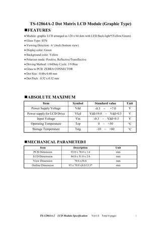
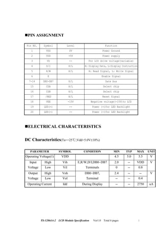
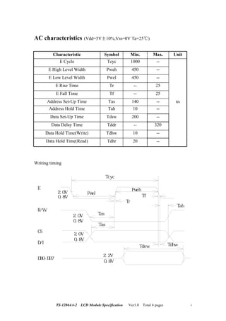
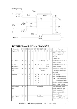
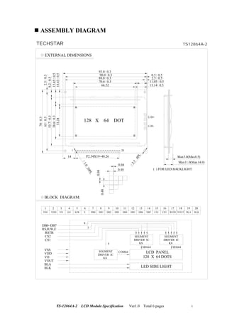
TS-12864A-2 LCD Module Specification Ver1.0 Total 6 pages 1
Specification
For
LCD Module
TS-12864A-2
TS-12864A-2 LCD Module Specification Ver1.0 Total 6 pages 2
TS-12864A-2 Dot Matrix LCD Module (Graphic Type)
FEATURES
• Module: graphic LCD arranged as 128 x 64 dots with LED Back-light*(Yellow/Green)
• Glass Type: STN
• Viewing Direction : 6 ‘clock (bottom view)
• Display color: Green
• Background color: Yellow
• Polarizer mode: Positive, Reflective/Transflective
• Driving Method: 1/64Duty Cycle, 1/9 Bias
• Glass to PCB: ZEBRA CONNECTOR
• Dot Size : 0.48x 0.48 mm
• Dot Pitch : 0.52 x 0.52 mm
ABSOLUTE MAXIMUM
Item Symbol Standard value Unit
Power Supply Voltage Vdd -0.3 ∼ +7.0 V
Power supply for LCD Drive Vlcd Vdd-19.0 ~ Vdd+0.3 V
Input Voltage Vin -0.3 ~ Vdd+0.3 V
Operating Temperature Top 0 ~ +50 °C
Storage Temperature Tstg -10 ~ +60 °C
MECHANICAL PARAMETED/I
Item Description Unit
PCB Dimension 93.0 x 70.0 x 1.6 mm
LCD Dimemsion 84.0 x 51.0 x 2.6 mm
View Dimension 70.6 x38.6 mm
Outline Dimension 93 x 70.0 x8.0/13.5* mm
TS-12864A-2 LCD Module Specification Ver1.0 Total 6 pages 3
PIN ASSIGNMENT
Pin NO. Symbol Level Function
1 VSS 0V Power Ground
2 VDD +5V Power supply
3 VO -- For LCD drive voltage(variable)
4 D/I H/L H: Display Data, L:Display Instruction
5 R/W H/L H: Read Signal, L: Write Signal
6 E Enable Signal
7-14 DB0-DB7 H/L Date bus
15 CSA H/L Select chip
16 CSB H/L Select chip
17 /RES H/L Reset Signal
18 VEE -15V Negative voltage(-15V)to LCD
19 LED(+) -- Power (+)for LED Backlight
20 LED(-) -- Power (-)for LED Backlight
ELECTRICAL CHARACTERISTICS
DC Characteristics(Ta==25 ;Vdd=5.0V±10%)
PARAMETER SYMBOL CONDITION MIN TYP MAX UNIT
Operating Voltage(1) VDD 4.5 5.0 5.5 V
Input High Vih E,R/W,D/I,DB0~DB7 2.0 -- VDD V
Voltage Low Vil Terminals 0 -- 0.8
Output High Voh DB0~DB7, 2.4 -- -- V
Voltage Low Vol Terminal -- -- 0.4
Operating Current Idd During Display -- -- 2750 uA
TS-12864A-2 LCD Module Specification Ver1.0 Total 6 pages 4
AC characteristics (Vdd=5V 10%,Vss=0V Ta=25 )
Characteristic Symbol Min. Max. Unit
E Cycle Tcyc 1000 --
E High Level Width Pweh 450 --
E Low Level Width Pwel 450 --
E Rise Time Tr -- 25
E Fall Time Tf -- 25
Address Set-Up Time Tas 140 -- ns
Address Hold Time Tah 10 --
Data Set-Up Time Tdsw 200 --
Data Delay Time Tddr -- 320
Data Hold Time(Write) Tdhw 10 --
Data Hold Time(Read) Tdhr 20 --
Writing timing
E
 R/W
CS
D/I
DB0-DB7
Tcyc
Pwel2.0V
0.8V
2.0V
0.8V
2.0V
0.8V
2.2V
0.8V
Tdsw Tdhw
Tah
Tf
Tr
Tas
Tas
Pweh
TS-12864A-2 LCD Module Specification Ver1.0 Total 6 pages 5
Reading Timing
E
R/W
CS
DI
DB0 DB7
2.0V
0.8V
Pwel
Tcyc
Pweh
Tr
Tas
Tas
Tddr
2.4V
0.4V
Tdhr
Tah
Tf
TAH
2.0V
0.8V
2.0V
0.8V
CONTROL and DISPLAY COMMAND
Instruction R/W D/I DB7 DB6 DB5 DB4 DB3 DB2 DB1 DB0 Function
Display on/off L L L L H H H H H L/H Controls the display on or
off.Internal status and
display RAM data is not
affected.
L:OFF,H:ON
Set Address L L L H Y address (0~63) Sets the Y address in the Y
address counter.
Set Page
(X Address)
L L H L H H H page
(0~7)
Sets the X address at the X
address register.
Display Start
Line
L L H H Display start line
(0~63)
Indicates the display data
RAM display at the top of
the screen
Status read H L B
U
S
Y
L O
N
/
O
F
F
R
E
S
E
T
L L L L Read the status :
busy 1:working,0:ready
ADC 1:clockwise output
0:counterclockwise
ON/OFF 1:disp off 0:disp on
RESET 1:reset 0:normal
Write Display
Data
L H Write Data Write data (DB0:7) into
display data RAM. After
writing instruction, Y
address is increased by 1
automatically.
Read Display
Data
H H Read Data Read data (DB0:7) from
display data RAM to the data
bus
TS-12864A-2 LCD Module Specification Ver1.0 Total 6 pages 6
ASSEMBLY DIAGRAM
1 20
Max5.0(Max8.5)
Max11.0(Max14.0)
( ) FOR LED BACKLIGHT
VSS
1
VDD
2
VO
3
D/I
4
R/W
5
E
6
DB0
7
DB1
8
DB2
9
DB3
10
DB4
11
DB5
12
DB6
13
DB7
14
CS1
15
CS2
16
BLOCK DIAGRAM:
EXTERNAL DIMENSIONS
LED-
LED+
128 X 64 DOT
33.24
38.60.3
53.70.3
650.3
700.3
18.430.5
15.650.5
8.20.5
2.50.5
66.52
70.6 0.3
90.0 0.3
88.0 0.3
93.0 0.3
13.14 0.5
11.05 0.5
2.5 0.5
0.5 0.5
0.48
0.04
0.48
0.04
17
RSTB
18
VOUT
19
BLA
20
BLK
SEGMENT
DRIVER IC
KS
LCD PANEL
128 X 64 DOTS
LED SIDE LIGHT
SEGMENT
DRIVER IC
KS
SEGMENT
DRIVER IC
KS
SEG64 SEG64
BLK
DB0~DB7
RS,R/W,E
RSTB
CS2
CS1
BLA
VOUT
VO
VDD
VSS
8
3
5
COM64
14 P2.54X19=48.26
1.0
20PL
2.5
4PL
TECHSTAR TS12864A-2

MODULO TS-12864A-2

  • 1.
    TS-12864A-2 LCD ModuleSpecification Ver1.0 Total 6 pages 1 Specification For LCD Module TS-12864A-2
  • 2.
    TS-12864A-2 LCD ModuleSpecification Ver1.0 Total 6 pages 2 TS-12864A-2 Dot Matrix LCD Module (Graphic Type) FEATURES • Module: graphic LCD arranged as 128 x 64 dots with LED Back-light*(Yellow/Green) • Glass Type: STN • Viewing Direction : 6 ‘clock (bottom view) • Display color: Green • Background color: Yellow • Polarizer mode: Positive, Reflective/Transflective • Driving Method: 1/64Duty Cycle, 1/9 Bias • Glass to PCB: ZEBRA CONNECTOR • Dot Size : 0.48x 0.48 mm • Dot Pitch : 0.52 x 0.52 mm ABSOLUTE MAXIMUM Item Symbol Standard value Unit Power Supply Voltage Vdd -0.3 ∼ +7.0 V Power supply for LCD Drive Vlcd Vdd-19.0 ~ Vdd+0.3 V Input Voltage Vin -0.3 ~ Vdd+0.3 V Operating Temperature Top 0 ~ +50 °C Storage Temperature Tstg -10 ~ +60 °C MECHANICAL PARAMETED/I Item Description Unit PCB Dimension 93.0 x 70.0 x 1.6 mm LCD Dimemsion 84.0 x 51.0 x 2.6 mm View Dimension 70.6 x38.6 mm Outline Dimension 93 x 70.0 x8.0/13.5* mm
  • 3.
    TS-12864A-2 LCD ModuleSpecification Ver1.0 Total 6 pages 3 PIN ASSIGNMENT Pin NO. Symbol Level Function 1 VSS 0V Power Ground 2 VDD +5V Power supply 3 VO -- For LCD drive voltage(variable) 4 D/I H/L H: Display Data, L:Display Instruction 5 R/W H/L H: Read Signal, L: Write Signal 6 E Enable Signal 7-14 DB0-DB7 H/L Date bus 15 CSA H/L Select chip 16 CSB H/L Select chip 17 /RES H/L Reset Signal 18 VEE -15V Negative voltage(-15V)to LCD 19 LED(+) -- Power (+)for LED Backlight 20 LED(-) -- Power (-)for LED Backlight ELECTRICAL CHARACTERISTICS DC Characteristics(Ta==25 ;Vdd=5.0V±10%) PARAMETER SYMBOL CONDITION MIN TYP MAX UNIT Operating Voltage(1) VDD 4.5 5.0 5.5 V Input High Vih E,R/W,D/I,DB0~DB7 2.0 -- VDD V Voltage Low Vil Terminals 0 -- 0.8 Output High Voh DB0~DB7, 2.4 -- -- V Voltage Low Vol Terminal -- -- 0.4 Operating Current Idd During Display -- -- 2750 uA
  • 4.
    TS-12864A-2 LCD ModuleSpecification Ver1.0 Total 6 pages 4 AC characteristics (Vdd=5V 10%,Vss=0V Ta=25 ) Characteristic Symbol Min. Max. Unit E Cycle Tcyc 1000 -- E High Level Width Pweh 450 -- E Low Level Width Pwel 450 -- E Rise Time Tr -- 25 E Fall Time Tf -- 25 Address Set-Up Time Tas 140 -- ns Address Hold Time Tah 10 -- Data Set-Up Time Tdsw 200 -- Data Delay Time Tddr -- 320 Data Hold Time(Write) Tdhw 10 -- Data Hold Time(Read) Tdhr 20 -- Writing timing E  R/W CS D/I DB0-DB7 Tcyc Pwel2.0V 0.8V 2.0V 0.8V 2.0V 0.8V 2.2V 0.8V Tdsw Tdhw Tah Tf Tr Tas Tas Pweh
  • 5.
    TS-12864A-2 LCD ModuleSpecification Ver1.0 Total 6 pages 5 Reading Timing E R/W CS DI DB0 DB7 2.0V 0.8V Pwel Tcyc Pweh Tr Tas Tas Tddr 2.4V 0.4V Tdhr Tah Tf TAH 2.0V 0.8V 2.0V 0.8V CONTROL and DISPLAY COMMAND Instruction R/W D/I DB7 DB6 DB5 DB4 DB3 DB2 DB1 DB0 Function Display on/off L L L L H H H H H L/H Controls the display on or off.Internal status and display RAM data is not affected. L:OFF,H:ON Set Address L L L H Y address (0~63) Sets the Y address in the Y address counter. Set Page (X Address) L L H L H H H page (0~7) Sets the X address at the X address register. Display Start Line L L H H Display start line (0~63) Indicates the display data RAM display at the top of the screen Status read H L B U S Y L O N / O F F R E S E T L L L L Read the status : busy 1:working,0:ready ADC 1:clockwise output 0:counterclockwise ON/OFF 1:disp off 0:disp on RESET 1:reset 0:normal Write Display Data L H Write Data Write data (DB0:7) into display data RAM. After writing instruction, Y address is increased by 1 automatically. Read Display Data H H Read Data Read data (DB0:7) from display data RAM to the data bus
  • 6.
    TS-12864A-2 LCD ModuleSpecification Ver1.0 Total 6 pages 6 ASSEMBLY DIAGRAM 1 20 Max5.0(Max8.5) Max11.0(Max14.0) ( ) FOR LED BACKLIGHT VSS 1 VDD 2 VO 3 D/I 4 R/W 5 E 6 DB0 7 DB1 8 DB2 9 DB3 10 DB4 11 DB5 12 DB6 13 DB7 14 CS1 15 CS2 16 BLOCK DIAGRAM: EXTERNAL DIMENSIONS LED- LED+ 128 X 64 DOT 33.24 38.60.3 53.70.3 650.3 700.3 18.430.5 15.650.5 8.20.5 2.50.5 66.52 70.6 0.3 90.0 0.3 88.0 0.3 93.0 0.3 13.14 0.5 11.05 0.5 2.5 0.5 0.5 0.5 0.48 0.04 0.48 0.04 17 RSTB 18 VOUT 19 BLA 20 BLK SEGMENT DRIVER IC KS LCD PANEL 128 X 64 DOTS LED SIDE LIGHT SEGMENT DRIVER IC KS SEGMENT DRIVER IC KS SEG64 SEG64 BLK DB0~DB7 RS,R/W,E RSTB CS2 CS1 BLA VOUT VO VDD VSS 8 3 5 COM64 14 P2.54X19=48.26 1.0 20PL 2.5 4PL TECHSTAR TS12864A-2