
Recommended
More Related Content
Similar to Module1-8086 microprocessor Architecture
Similar to Module1-8086 microprocessor Architecture (20)
Recently uploaded
Recently uploaded (20)
Module1-8086 microprocessor Architecture
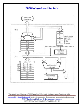
- 1. Prepared by : Malabika Pattnaik, Faculty (Department of Electronics and Communication Engineering) NIST Institute of Science & Technology(AUTONOMOUS) INSTITUTE PARK, PALLUR HILLS, BERHAMPUR, ODISHA -761 008 8086 Internal architecture The complete architecture of 8086 can be divided into two independent functional units.
- 2. Prepared by : Malabika Pattnaik, Faculty (Department of Electronics and Communication Engineering) NIST Institute of Science & Technology(AUTONOMOUS) INSTITUTE PARK, PALLUR HILLS, BERHAMPUR, ODISHA -761 008 a) BIU (Bus Interface Unit) b) EU (Execution Unit) Dividing the work between these two units’ speeds up processing. Functions of BIU The bus interface unit makes the system’s bus signals available for external interfacing of the devices. It provides the interface of 8086 to external memory and I/O devices via the System Bus. It performs various machine cycles such as memory read, I/O read etc. to transfer data between memory and I/O devices. BIU performs the following functions- It generates the 20 bit physical address for memory access. It fetches instructions from the memory. It transfers data to and from the memory and I/O. Maintains the 6 byte pre-fetch instruction queue Components of BIU BIU mainly contains : 4 Segment registers :CS, DS, SS and ES Instruction Pointer (IP) 6-byte pre-fetch queue (IQ) Address Generation Circuit. 4 Segment registers : CS, DS, SS and ES: The segment registers indicates the base address of a particular segment. Instruction Pointer (IP): It is a 16 bit register. It holds offset of the next instructions in the Code Segment. IP is incremented after every instruction byte is fetched. IP gets a new value whenever a branch instruction occurs. CS is multiplied by 10H to give the 20 bit physical address of the Code Segment.
- 3. Prepared by : Malabika Pattnaik, Faculty (Department of Electronics and Communication Engineering) NIST Institute of Science & Technology(AUTONOMOUS) INSTITUTE PARK, PALLUR HILLS, BERHAMPUR, ODISHA -761 008 Address of the next instruction is calculated as CS x 10H + IP. 6-byte pre-fetch Instruction queue (IQ): It is a 6-byte FIFO (First-In-First-Out) register structure. To increase the execution speed, BIU fetches as many as six instruction bytes ahead to time from memory. The pre fetched instruction bytes are held for the EU in a first in first out group of registers called an instruction queue. When the EU is ready for its next instruction, it simply reads the instruction from this instruction queue. This is much faster than sending out an address to the system memory and to send back the next instruction byte. Minimum two empty space required in IQ from i/p side to perform fetching operation. The instructions byte from the queue are taken to EU for decoding sequentially. Once a byte is decoded, the queue is rearranged by pushing it out and the queue status is checked for the possibility of the next op-code fetch cycle.
- 4. Prepared by : Malabika Pattnaik, Faculty (Department of Electronics and Communication Engineering) NIST Institute of Science & Technology(AUTONOMOUS) INSTITUTE PARK, PALLUR HILLS, BERHAMPUR, ODISHA -761 008 Address Generation Circuit: The BIU has a Physical Address Generation Circuit. It generates the 20 bit physical address using Segment and Offset addresses using the formula: Physical Address = Segment Address x 10H + Offset Address Functions & Components of EU The EU contains the register set except segment registers and IP. It has 16-bit ALU, able to perform arithmetic and logical operations. The 16-bit flag register reflects the results of execution by the ALU. The decoding unit decodes the op-code bytes issued from the instruction queue. The timing and control unit derives the necessary control signals to execute the instruction op-code received from the queue, depending upon the information made available by the decoding circuit. The execution unit may pass the results to the bus interface unit for storing them in memory. Working principle of the architecture BIU and EU working independently. While EU executing the fetched instruction internally , by that time external bus of BIU used to fetch the machine code of the next instruction and arrange it in a queue known as pre-decoded instruction byte Queue. While the op-code is fetched by the BIU, the EU executes the previously decoded instruction concurrently. The BIU along with the EU thus forms a pipeline. It is called pipelining execution or parallel processing . Pipelining has become possible due to the use of queue. It increases the speed of execution process. 8086 processor architecture support two stage pipelining because of two functional unit..
- 5. Prepared by : Malabika Pattnaik, Faculty (Department of Electronics and Communication Engineering) NIST Institute of Science & Technology(AUTONOMOUS) INSTITUTE PARK, PALLUR HILLS, BERHAMPUR, ODISHA -761 008 Pipelining execution Three operations of microprocessor during the instructions execution are: Assume three clock cycles are required to execute one instructions. The instructions can be executed in sequential manner or pipelined manner. In case of sequential execution, first instruction is executed in three clock cycles assuming that each of phase is done in one clock cycle. The second instruction is begins only after first is completed i.e. in fourth clock cycle. To execute four instructions 12 clock cycles needed as shown in figure. In case of a pipelined execution during decoding of first instruction, the fetching of second instruction becomes started. Before the end of execution of first instruction third instruction fetching and second instruction decoding operation becomes started as shown in the figure. To execute four instructions only 6 clock cycles are needed. It is called three stage pipelining.