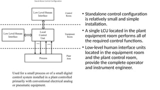
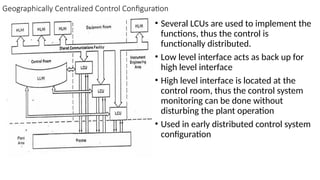
Module 5
OPERATOR INTERFACE
INTRODUCTION
• Automated equipment to be used in a safe and effective manner.
• It is absolutely necessary to have a well-engineered human interface
system to permit error-free interactions between the humans and the
automated system.
Stand-Alone Control Configuration
• Standalone control configuration
is relatively small and simple
installation.
• A single LCU located in the plant
equipment room performs all of
the required control functions.
• Low-level human interface units
located in the equipment room
and the plant control room,
provide the complete operator
and instrument engineer.
Used for a small process or of a small digital
control system installed in a plant controlled
primarily with conventional electrical analog
or pneumatic equipment.
Geographically Centralized Control Configuration
• Several LCUs are used to implement the
functions, thus the control is
functionally distributed.
• Low level interface acts as back up for
high level interface
• High level interface is located at the
control room, thus the control system
monitoring can be done without
disturbing the plant operation
• Used in early distributed control system
configuration
Geographically Distributed Control Configuration
• LCU is located in the plant area closest
to the portion of the process that it
controls.
• Associated low-level human interface
equipment is also located in this area.
• The control room and instrument
engineering areas contain high-level
human interface units, which are used
to perform all of the primary
operational and engineering functions.
• The low-level units are used only as
manual backup controls in case the
high-level equipment fails or needs
maintenance.
Advantages
• Reduction in control room size (by eliminating panelboard
equipment),
• Reduction in field wiring costs (by placing LCUs near the process).
Applications
• Large as well as small systems.
• Centralized equipment configuration (often used in retrofit
installations made long after original plant construction) as well as
distributed ones (likely in “grass roots” installation made during plant
construction).
• Variety of human interface philosophies, ranging from accepting CRT
only operation to requiring panelboard instrumentation in at least a
backup role.
Low-Level Operator Interface
• LLOI connected directly to the LCU and is dedicated to controlling and
monitoring that LCU.
• LLOIs are used in a variety of applications, in some cases in conjunction
with high-level operator interfaces (HLOIs) and in others in place of them.
• It provides an interface that is familiar to trained operators to use panel board
instrumentation, since it is usually designed to resemble that type of
instrumentation.
• It is usually less expensive than an HLOI in small applications.
• It can provide manual backup in case the automatic control equipment or HLOI
fails.
• LLOI instrumentation usually includes the following devices: control
stations, indicator stations, alarm annunciators, and trend recorders
• Continuous Control Station: One type of panel
board instrumentation used in process control
systems is the manual / automatic station associated
with a continuous control loop. The continuous
control stations are split from LCU.
• control station has one bar graph indicators that
display the process variable associated set point
(“SP”)& the control output as a percent of scale
(“OUT”).
• the smart station includes a shared digital display to
provide a precise reading of each of these variables
in engineering units.
• The shared digital display also can be used to
indicate the high and low alarm limits
• Pushbuttons allow the operator to change the mode of control and to ramp the
set point (“SET”) or control output (“OUT”), depending on the mode. To
minimize requirements for spare parts, one basic control station should be used
for all types of control loops.
• Manual Loader Station:
• A device is still needed to hold the 4-20mA control output signal if the LCU fails
or is taken off-line for maintenance or other reasons.
• A simple manual loader station is a low cost alternative to the continuous
control station for the purposes of backup.
• The manual loader station is plugged in at the same point as the continuous
control station but only allows the operator to run the loop in manual mode.
• Both the continuous control station and the manual loaders station should be
powered from a different supply than that used for the LCU, to ensure
continuous backup in case of an LCU power failure.
Indicator Station
• similar to the control station in that it provides both bar graph and digital
numeric readouts
• an indicator station requires no control push buttons
• it often provides alarming and LCU diagnostic indications, as does the
continuous control station
Logic Station:
• control station for a logic control or
sequential control system.
• It consists simply of a set of push
buttons and indicating lights.
• used to turn pumps on and off, start
automatic sequences, or provide
permissive or other operator inputs to
the logic system.
• performs a manual backup function
• the logic station acts simply as a low
cost operator interface.
LOGIC CONTROL STATION
Smart Annunciators:
• are microprocessor based alarms providing a level of functionality beyond the
capability of conventional hard-wired annunciator systems. These smart
annunciators can provide such functions as:
• Alarm prioritization: The annunciator differentiates between status annunciation
and true alarms.
• Annunciation and acknowledgement mode options: The operator receives a
variety of audible and visible alarm annunciation signals like horn, buzzers,
flashing lights, and voice messages.
• First-out annunciation: The annunciator displays the first alarm that appears
within a selected group.
• Alarm “cutout”: The annunciator suppresses an alarm condition if other specified
statuses conditioned are fulfilled.
• Chart Recorders:
• round chart or strip chart recorders, digital recorders which use microprocessors
are used to record process variables in
• The digital recorder gathers trend data in its memory and displays the data to the
operator using a liquid crystal panel or other flat display device.
• Each process variable can be recorded using a different symbol or colour to allow
the operator to distinguish between the variables easily.
• Because of the flexibility of the printing mechanism and the memory capabilities
of the recorder
• intermittent printing of the process variables can supplement the display output
without losing any of the stored information.
• High-Level Operator Interface
• The high-level operator interface in a DCS is a shared interface that is not
dedicated to any particular LCU.
• HLOI is used to monitor and control the operation of the process through
any or all of the LCUs in the distributed system.
• Information passes between the HLOI and the LCUs by means of the
shared communications facility.
• LLOI hardware resembles conventional panelboard instrumentation
• HLOI hardware uses CRT or similar advanced display technology in console
configurations often called video display units (VDUs).
• HLOI accepts operator inputs through keyboards instead of the switches,
push buttons, and potentiometers characteristic of conventional operator
interface panels.
• In general, the use of microprocessor-based digital technology in the
design of HLOI system allows the development of a hardware
configuration. This configuration provides the user with several significant
advantages over previous approaches.
• Control room space is reduced significantly; one or a few VDUs can replace panel
boards several feet to 200 feet in length, saving floor space and equipment
expense.
• One can design the operator interface for a specific process plant in a much more
flexible manner. There is no panel board instrumentation operation.
• Using microprocessors permits cost effective implementation of functions that
previously could be accomplished only with expensive computers
• Architectural Alternatives
• All HLOI units in distributed control systems are consists of operator display,
keyboard or other input device, main processor and memory, disk memory
storage, interface to the shared communication facility, and hard copy devices
and other peripherals.
• the architectures of the various HLOIs on the market vary significantly
depending on the way in which these common elements are structured
CENTRALIZED HLOI CONFIGURATION
• a single central processing unit that performs
all of the calculations, database management
and transfer operations, and CRT and keyboard
interfacing functions for the entire HLOI system.
• A separate communication controller
interfaces the central processor with the shared
communications facility
• there is a single database of plant information
that is updated from the communication
system.
• each of the CRTs has access to any of the
control loops or data points in the system.
• the CRTs are all redundant and can be used to
back each other up in case of a failure. The
• peripherals can be shared and need not be
dedicated to any particular CRT/keyboard
combination.
DISADVANTAGES
• vulnerable to single point failures.
In some cases, redundant element
can be provided.
• Any single processor, single
memory configuration has
limitations on the number of
loops and data points it can
handle before its throughput or
memory capacity runs out.
• The centralized architecture is not
easily scalable for cost
effectiveness; if it is designed
properly to handle large systems,
it may be too expensive for small
ones
CENTRALIZED HLOI CONFIGURATION
Overlap in HLOI Scope of Control
• Figure shows two-to-one overlap configuration, in which three HLOI
units control and monitor a 600 loop process.
• With this approach, the loss of any single HLOI unit does not affect
the capability of the operator interface system to control the process.
• This design approach results in a more expensive version of an HLOI
than one designed to handle a smaller number of points.
• in this case each HLOI unit is capable of backing up any other unit in
the system
Fixed HLOI Configuration
• In fixed HLOI configuration there is a single HLOI unit consisted of a
communications controller, main processor, CRT and keyboard, and
associated mass storage.
• The only option for the user was whether to include a printer or other
hard copy device.
• Because of this fixed configuration of elements, the scope of control
and data acquisition of the HLOI unit also was fixed.
Modular HLOI Configuration
• The base set of hardware in this case is a communications controller, main
processor, single CRT and keyboard, and mass storage unit.
• One or more additional CRTs to allow monitoring of a portion of the process
while the primary CRT is being used for control purposes.
• Additional keyboards for configuration or backup purposes.
• Hard copy devices such as printers or CRT screen copiers.
• Additional mass storage devices for long term data storage and retrieval.
• Interfaces to trend recorders, voice alarm systems, or other external
hardware.
• Interface ports to any special communication systems such as back door
networks to other HLOI units or diagnostic equipment.
• Backups to critical HLOI elements such as the main processor,
communications controller, or shared memory.
MODULAR HLOI CONFIGURATION IN DETAIL
• this configuration uses a direct memory access (DMA) port to allow
the communications controller to transfer data directly into the
shared memory of the HLOI.
• The other elements of the HLOI then can obtain access to this
information over the internal bus.
Displays
• Group Display
• overview Display
• Detail Display
• Graphic Display
• Trend Display
DISPLAYS
• Plant Level: Gives information concerning the entire plant & can be broken up
to several areas of interest
• Area Level: Gives information concerning a portion of the plant equipment
• Group Level: Deals with the control loops & data points related to a single unit
within a plant area
• Loop Level : Deals with individual control loops, control sequences and data
points.
• One process variable is plotted as a function of another to show the current
operating point
• Operator then compares this operating points against the alarm limit
Display hierarchy
Plant-Level Displays
• Gives information concerning the entire plant & can be broken up to
several areas of interest
• Overall production level
• How well the plant is running
• Gives information about process alarm & equipment diagnosis alarm
Area-leveI Displays
• Gives information concerning a portion of the plant equipment
• Area graphic Display
• similar to P&ID diagram
• Gives alarm status current values of the process variable
• Alarm Summary Display
• Gives alarms that are still outstanding in the area
• Group Level Display: Deals with the control loops & data points related to a
single unit within a plant area
• Loop Level : Deals with individual control loops, control sequences and data
points.
• One process variable is plotted as a function of another to show the current
operating point
• Operator then compares this operating points against the alarm limit
Group Display
Over View Display
Detail Display
Graphic Display
Trends Display
ENGINEERING INTERFACE
• The human interfaces that allow the plant operator to monitor and control the
process, an engineering interface that is totally independent of the operator
interface
• Engineering Interface Requirements
• had to select and procure the control and data acquisition modules, mount
them in cabinets, and do a significant amount of custom wiring between
modules.
• engineers had to test and check out the entire system manually prior to field
installation
• select operator interface instrumentation, mount it in panel boards, wire it up,
and test it.
• prepare documentation for the entire configuration of control and operator
interface hardware and the corresponding control logic diagrams, usually from
manually generated drawings.
• System Configuration: Define hardware configuration and interconnections, as
well as control logic and computational algorithms.
• Operator Interface Configuration: Define equipment that the operator needs
to perform his or her functions in the system, and define the relationship of this
equipment with the control system itself.
• System Documentation: Provide a mechanism for documenting the system and
the operator interface configuration and for making changes quickly and easily.
• System Failure Diagnosis: Provide a mechanism to allow the instrument
engineering to determine the existence and location of failures in the system in
order to make repairs quickly and efficiently
Low Level Engineering Interface
• The low-level engineering interface (LLEI) is designed to be a minimum
function, inexpensive device whose cost is justifiable for small distributed
control systems. It also can be used as a local maintenance and diagnostic tool
in larger systems.
• The LLEI is usually a microprocessor based device designed either as an electronic
module that mounts in a rack or as a hand held portable device.
• To minimize cost, the device usually is designed with a minimal keyboard and
alphanumeric display so that the instrument engineer can read data from and
enter data into the device.
• Some versions of the LLEI must connect directly to and communicate with only
one local control unit or data input / output unit at a time.
• The LLEI can be connected or disconnected while the LCU or DI/OU is powered
and in operation; it is not necessary to shut down the process.
• In general, the LLEI is a dedicated device that is not used for operational
purposes.
System Configuration:
• When the system provides only an LLEI, the hardware in the system is selected
and configured manually.
• To simplify this task, provide a system engineering guide or documentation.
• The primary purpose of the LLEI is to provide a tool for configuring the algorithms
in the system
• In some low-level interface removable mass memory devices is available and
without controller engineer can edit control strategies only with power supply.
• The LLEI is not support high-level language program.
Operator Interface Configuration:
• Minimum devices – manually
• Assign tag names, labelling station
• Difficult, time consuming, prone to error
• Documentation
Manual – with standard forms
Diagnosis Of System Problems
• – Not always connected
• – Rely on Self test of equipment
High-Level Engineering Interface
• The HLEI is implemented in the form of a CRT based console or VDU, similar to
the high level operator interface unit.
• Flexibility in accommodating hardware’s, like special keyboards or printers.
• Same elements of operator interface used for engineering interface.
• Like the VDU, the engineering console can interact with any other elements in
DCS through the shared communication facility
• Dual Console Functions: The engineering console is a specialized device that is
dedicated to the engineering function
• the engineering console can also be used as an operator’s console; a key lock
on the console implements the switch between the two console “personalities”
• The first key position permits only operator functions like display selection,
control operations such as mode selection and set point modification, and
trend graph selection.
• The second position allows engineering functions such as control logic
configuration, modification and tuning, and system documentation as well as
operator functions.
• Some systems provide a third key lock position that allows the user to perform
tuning operations but does not allow the user to modify the control logic
structure.
• Implementing dual console “personalities” in a single piece of hardware is very
cost effective for the user
Special Hardware Required:
• The operator’s console uses a flat panel, dedicated function keyboard for
ruggedness and simplicity of operation. The engineer’s console requires a general
purpose keyboard to promote speed of data entry and to support a wider range
of human interface functions.
• additional special purpose keys to allow the user to select special characters,
symbols, and colors employed in generating control configurations and displays.
• special color graphic printing or plotting devices, which allow more sophisticated
system documentation to be generated than is possible with standard printer that
comes with an operator’s console
• Portable Engineering Interface:
• In DCS, CRT based engineering interface device that is a compromise between
the full function engineering console and the minimum function.
• Usually, this is a portable unit that includes a bulk memory device such as a
floppy disk or cassette tape drive for storage of system configuration data.
• This unit generally is designed to plug into and interface with a single LCU or
cabinet.
• It can be very useful and cost effective device for certain system configurations.
System Configuration
• HLEI – major role in automating process
• Control structures, computational algorithm stored in HLEI. Following information
• – Number, type and location of H/W in LCU
• – Definition of any H/W selected on each module
• – Define input point to H/W module
• – Number, type and location of all operator and engineering consoles in the system
• – Number, type and location of any other device that communicate using shared
communication facility(special logging or computing device)
• • Some manually others automatic using broadcast messages
• Control and computational information
• – Tags, descriptors, definitions, addresses
• – Logic state descriptors for digital system
• – Signal conditioning in DI/OUs
• – Communication linkages
• – High-level language computation algorithms in LCU
• Control and computational logic configuration
• Fill-in-the-blanks function; through sequence of prompts and responses
• Graphics capability engineer draws using light pen, similar to CAD
• Enter debug and check high level language routines
• Storage of configuration
• • Use of mass memory to store configuration information
• – Control logics without presence of target H/W
• – Verify engineer input to LCU; comparison from mass storage
• – Failed devices replaced with new one, configuration downloaded to it
• – Upload configuration from device to interface
• Operator interface configuration
• • Configure or change display structures
• – Number of areas in plant, identifying tags and descriptors
• – Number of groups in each area
• – Assignment of control loops and input points to group
• – Types of display at each level (preformatted or custom)
• – Linkages between displays
• – Assignment of points in system for special function
• • Layout of display
• – Graphic symbols
• – Static background elements
• – Dynamic graphics elements
• – Dynamic alphanumeric elements
• – Control stations
• – Poke points- touch screen
• Operator input mechanisms
• – Special function definition
• – Graphics drawing and editing
• – Symbol modifications
• – Macro symbol operations
• – Display transportability
• – Expanded display definition
• Documentation
• • Following documentation automatically
• – List of H/W modules and their location
• – Control configuration and associated tuning parameters for each LCU
• – Listing of tags, descriptors, H/W address of I/P or O/P modules
• – Listing of special operator interface function with tag
• – Operator display in system with drawing and display hierarchy
• Diagnosis of system problems
• • Most of H/W devices is microprocessor based, intelligent to perform on-line
self-diagnosis
General Purpose Computers in DCS
• Software Investment:
• The user already may have invested considerable time and resources in
software packages that run on a specific computer.
• The cost of converting these packages to a form that would run in a vendor’s
distributed computing environment may not be worth the benefits.
• Specialized Language Requirements:
• The user’s application may be implemented most readily by means of a
software language that is not available in the system provided by the
distributed control vendors.
• Extensive Computational Requirements:
• The speed and memory requirements of a particular application may
preclude the use of microprocessor-based devices.
• Some examples of large computing application of this type include
modelling large dynamic systems, running large linear and non-linear
programs, and identifying the dynamics of high order systems.
DCS Detailed ENGINEERING
• Detailed engineering encompasses the design and configuration of various
engineering systems that form the internal workings of a facility, including
• Process design & specification
• Mechanical design & specification
• Piping design & specification
• Structural design & specification
• Electrical design & specification
• Instrumentation design & specification
• Control system design & specification
• Process Design & Specification
• Process design criteria development
• Process functional description
• Design & development
• Process flow design (PFD)
• Mass balance
• Heat & energy
• P&IDs
• Continuous/batch processing
• Equipment sizing
• Process safety management Mechanical Design & Specification
• Mechanical Design & Specification
• Layouts designed for constructability, reliability, operations, & maintenance
• HVAC, including ventilation & hood design
• Dust control & aspiration
• Sheet metal & spouting
• Equipment specification development
• Piping Design & Specification
• Layout
• Stress analysis
• Aseptic & sanitary design (ASME BPE)
• Plumbing
• ASME B31.1 reviews
• Underground systems
• Structural Design & Specification
• Field supervision
• Facility planning & evaluation
• Facility expansion
• Value engineering
• Structural design analysis
• Electrical Design & Specification
• Low- & high-voltage design
• Design criteria development
• Single-line design
• XFMR, switchgear, & MCC design
• Electrical grounding
• Heat tracing
• Power system studies
• Lighting design
• Power-factor coordination studies
• Lightning protection
• Instrumentation Design & Specification
• Design criteria development
• Instrument specifications & selection
• P&ID control-loop design & layout
• Instrument loop diagrams
• Control & input/output panel design
• Input/output check-out
• Control System Design & Specification
• Instrument specifications, tailored to each job
• Design calculations
• Fieldbus installation, designed to specification
• Control & interface panel design
• Electrical power system design, 4.5 kV & below
• Electrical system analysis
• Programming & Configuration
• PLC & DCS systems
• HMI graphics development
• UPS & back-up systems
• Networked control systems
• Automation
• Project Management
• Detailed proposals
• Project monitoring & weekly/monthly reporting
• Design coordination
• Labour utilization
• Cost estimating & overall analysis
• Scheduling
• Document control
Reporting in DCS
• Reporting is critical to operation, productivity, and regulatory
requirement.
• The Reporting function is provided through easily configurable report
templates based on Microsoft®Excel®.
• Periodic and event-triggered reports can be configured to query real-
time and historical data.
• Periodic reports can be set up for hourly, shift, monthly, etc.
• Event-driven reports can be configured to record start/end time,
duration, time-stamped max/min values, etc., and triggered by a
digital point
Fault Detection and Diagnosis in DCS
• Fault detection and diagnostics is central to system stability and reliability.
• When a problem occurs in the system, the fault detection and diagnostic
function of DCS quickly analyze the cause of the failure by examining
historical data and sequential event records.
• This allows maintenance personnel to pinpoint the cause and location,
and to determine a response.
• The system detection and diagnostic software monitors the status on
several levels of
• Network
• Network Node
• I/O Station
• I/O module
• I/O channel
Data Base management in DCS
• A database is an organized collection of data, generally stored and
accessed electronically from a computer system.
• The database management system (DBMS) is the software that interacts
with end users, applications, the database itself to capture and analyze
the data and provides facilities to administer the database.
• The sum total of the database, the DBMS and the associated applications
can be referred to as a "database system".
• In high data throughput applications, although the need for database
systems has been identified
• Conventional database management system are slow and bulky,
requiring an interface like Structured Query Language (SQL) to access
data.
• Allows access and manipulate databases
• The SQL interfaces have been difficult to set up, often representing a
bottleneck between the plant floor and the higher level enterprise
systems, both in sending data up from the plant floor to be analyzed,
and down to the plant processes to be acted upon.
• An alternative data management approach that meets the needs of
all levels of industrial automation is the embedded database,
• which can be closely integrated with real-time automation processes,
and which can manage live real-time data streams.
• These data management systems can take captured live data, process
it (aggregating and simplifying the data as required) and then
distribute it to deliver visualization and analytics that will enable
meaningful control decisions to be made.
Programming in DCS
• Response time. PLCs generally have a much quicker response time than DCSs,
given their size and capability, so they should be used for processes that have time
as a factor, such as building safety tasks (sprinkler systems or fire prevention
measures).
• Scale. PLCs operate on a smaller scale than a DCS. If your facility is large and/or
must handle a large number of tasks, a DCS is optimal.
• Redundancy. Trying to force a number of redundant tasks into a PLC program will
drive up your operating costs rather than using a DCS.
• Complexity. Like redundancy, a DCS handles complex and continuous tasks more
easily than a PLC. (However, some operations, such as pulp and paper
manufacturing, are trending toward PLCs.)
• Process changes. A PLC is better equipped to handle a task that will not require
much tweaking, so if your operation requires frequent changes in processes, a DCS
is a better option.
• Vendor support.
Programming language used in DCS
• Uses the functional Block diagram programming language

module five operator interface engineering

  • 1.
  • 2.
    INTRODUCTION • Automated equipmentto be used in a safe and effective manner. • It is absolutely necessary to have a well-engineered human interface system to permit error-free interactions between the humans and the automated system.
  • 3.
    Stand-Alone Control Configuration •Standalone control configuration is relatively small and simple installation. • A single LCU located in the plant equipment room performs all of the required control functions. • Low-level human interface units located in the equipment room and the plant control room, provide the complete operator and instrument engineer. Used for a small process or of a small digital control system installed in a plant controlled primarily with conventional electrical analog or pneumatic equipment.
  • 4.
    Geographically Centralized ControlConfiguration • Several LCUs are used to implement the functions, thus the control is functionally distributed. • Low level interface acts as back up for high level interface • High level interface is located at the control room, thus the control system monitoring can be done without disturbing the plant operation • Used in early distributed control system configuration
  • 5.
    Geographically Distributed ControlConfiguration • LCU is located in the plant area closest to the portion of the process that it controls. • Associated low-level human interface equipment is also located in this area. • The control room and instrument engineering areas contain high-level human interface units, which are used to perform all of the primary operational and engineering functions. • The low-level units are used only as manual backup controls in case the high-level equipment fails or needs maintenance.
  • 6.
    Advantages • Reduction incontrol room size (by eliminating panelboard equipment), • Reduction in field wiring costs (by placing LCUs near the process).
  • 7.
    Applications • Large aswell as small systems. • Centralized equipment configuration (often used in retrofit installations made long after original plant construction) as well as distributed ones (likely in “grass roots” installation made during plant construction). • Variety of human interface philosophies, ranging from accepting CRT only operation to requiring panelboard instrumentation in at least a backup role.
  • 8.
    Low-Level Operator Interface •LLOI connected directly to the LCU and is dedicated to controlling and monitoring that LCU. • LLOIs are used in a variety of applications, in some cases in conjunction with high-level operator interfaces (HLOIs) and in others in place of them. • It provides an interface that is familiar to trained operators to use panel board instrumentation, since it is usually designed to resemble that type of instrumentation. • It is usually less expensive than an HLOI in small applications. • It can provide manual backup in case the automatic control equipment or HLOI fails. • LLOI instrumentation usually includes the following devices: control stations, indicator stations, alarm annunciators, and trend recorders
  • 9.
    • Continuous ControlStation: One type of panel board instrumentation used in process control systems is the manual / automatic station associated with a continuous control loop. The continuous control stations are split from LCU. • control station has one bar graph indicators that display the process variable associated set point (“SP”)& the control output as a percent of scale (“OUT”). • the smart station includes a shared digital display to provide a precise reading of each of these variables in engineering units. • The shared digital display also can be used to indicate the high and low alarm limits
  • 10.
    • Pushbuttons allowthe operator to change the mode of control and to ramp the set point (“SET”) or control output (“OUT”), depending on the mode. To minimize requirements for spare parts, one basic control station should be used for all types of control loops. • Manual Loader Station: • A device is still needed to hold the 4-20mA control output signal if the LCU fails or is taken off-line for maintenance or other reasons. • A simple manual loader station is a low cost alternative to the continuous control station for the purposes of backup. • The manual loader station is plugged in at the same point as the continuous control station but only allows the operator to run the loop in manual mode. • Both the continuous control station and the manual loaders station should be powered from a different supply than that used for the LCU, to ensure continuous backup in case of an LCU power failure.
  • 11.
    Indicator Station • similarto the control station in that it provides both bar graph and digital numeric readouts • an indicator station requires no control push buttons • it often provides alarming and LCU diagnostic indications, as does the continuous control station
  • 12.
    Logic Station: • controlstation for a logic control or sequential control system. • It consists simply of a set of push buttons and indicating lights. • used to turn pumps on and off, start automatic sequences, or provide permissive or other operator inputs to the logic system. • performs a manual backup function • the logic station acts simply as a low cost operator interface. LOGIC CONTROL STATION
  • 13.
    Smart Annunciators: • aremicroprocessor based alarms providing a level of functionality beyond the capability of conventional hard-wired annunciator systems. These smart annunciators can provide such functions as: • Alarm prioritization: The annunciator differentiates between status annunciation and true alarms. • Annunciation and acknowledgement mode options: The operator receives a variety of audible and visible alarm annunciation signals like horn, buzzers, flashing lights, and voice messages. • First-out annunciation: The annunciator displays the first alarm that appears within a selected group. • Alarm “cutout”: The annunciator suppresses an alarm condition if other specified statuses conditioned are fulfilled.
  • 14.
    • Chart Recorders: •round chart or strip chart recorders, digital recorders which use microprocessors are used to record process variables in • The digital recorder gathers trend data in its memory and displays the data to the operator using a liquid crystal panel or other flat display device. • Each process variable can be recorded using a different symbol or colour to allow the operator to distinguish between the variables easily. • Because of the flexibility of the printing mechanism and the memory capabilities of the recorder • intermittent printing of the process variables can supplement the display output without losing any of the stored information.
  • 15.
    • High-Level OperatorInterface • The high-level operator interface in a DCS is a shared interface that is not dedicated to any particular LCU. • HLOI is used to monitor and control the operation of the process through any or all of the LCUs in the distributed system. • Information passes between the HLOI and the LCUs by means of the shared communications facility. • LLOI hardware resembles conventional panelboard instrumentation • HLOI hardware uses CRT or similar advanced display technology in console configurations often called video display units (VDUs). • HLOI accepts operator inputs through keyboards instead of the switches, push buttons, and potentiometers characteristic of conventional operator interface panels.
  • 16.
    • In general,the use of microprocessor-based digital technology in the design of HLOI system allows the development of a hardware configuration. This configuration provides the user with several significant advantages over previous approaches. • Control room space is reduced significantly; one or a few VDUs can replace panel boards several feet to 200 feet in length, saving floor space and equipment expense. • One can design the operator interface for a specific process plant in a much more flexible manner. There is no panel board instrumentation operation. • Using microprocessors permits cost effective implementation of functions that previously could be accomplished only with expensive computers
  • 17.
    • Architectural Alternatives •All HLOI units in distributed control systems are consists of operator display, keyboard or other input device, main processor and memory, disk memory storage, interface to the shared communication facility, and hard copy devices and other peripherals. • the architectures of the various HLOIs on the market vary significantly depending on the way in which these common elements are structured
  • 18.
    CENTRALIZED HLOI CONFIGURATION •a single central processing unit that performs all of the calculations, database management and transfer operations, and CRT and keyboard interfacing functions for the entire HLOI system. • A separate communication controller interfaces the central processor with the shared communications facility • there is a single database of plant information that is updated from the communication system. • each of the CRTs has access to any of the control loops or data points in the system. • the CRTs are all redundant and can be used to back each other up in case of a failure. The • peripherals can be shared and need not be dedicated to any particular CRT/keyboard combination. DISADVANTAGES • vulnerable to single point failures. In some cases, redundant element can be provided. • Any single processor, single memory configuration has limitations on the number of loops and data points it can handle before its throughput or memory capacity runs out. • The centralized architecture is not easily scalable for cost effectiveness; if it is designed properly to handle large systems, it may be too expensive for small ones
  • 19.
  • 20.
    Overlap in HLOIScope of Control
  • 21.
    Overlap in HLOIScope of Control • Figure shows two-to-one overlap configuration, in which three HLOI units control and monitor a 600 loop process. • With this approach, the loss of any single HLOI unit does not affect the capability of the operator interface system to control the process. • This design approach results in a more expensive version of an HLOI than one designed to handle a smaller number of points. • in this case each HLOI unit is capable of backing up any other unit in the system
  • 22.
  • 23.
    Fixed HLOI Configuration •In fixed HLOI configuration there is a single HLOI unit consisted of a communications controller, main processor, CRT and keyboard, and associated mass storage. • The only option for the user was whether to include a printer or other hard copy device. • Because of this fixed configuration of elements, the scope of control and data acquisition of the HLOI unit also was fixed.
  • 24.
  • 25.
    Modular HLOI Configuration •The base set of hardware in this case is a communications controller, main processor, single CRT and keyboard, and mass storage unit. • One or more additional CRTs to allow monitoring of a portion of the process while the primary CRT is being used for control purposes. • Additional keyboards for configuration or backup purposes. • Hard copy devices such as printers or CRT screen copiers. • Additional mass storage devices for long term data storage and retrieval. • Interfaces to trend recorders, voice alarm systems, or other external hardware. • Interface ports to any special communication systems such as back door networks to other HLOI units or diagnostic equipment. • Backups to critical HLOI elements such as the main processor, communications controller, or shared memory.
  • 26.
  • 27.
    • this configurationuses a direct memory access (DMA) port to allow the communications controller to transfer data directly into the shared memory of the HLOI. • The other elements of the HLOI then can obtain access to this information over the internal bus.
  • 28.
    Displays • Group Display •overview Display • Detail Display • Graphic Display • Trend Display
  • 29.
    DISPLAYS • Plant Level:Gives information concerning the entire plant & can be broken up to several areas of interest • Area Level: Gives information concerning a portion of the plant equipment • Group Level: Deals with the control loops & data points related to a single unit within a plant area • Loop Level : Deals with individual control loops, control sequences and data points. • One process variable is plotted as a function of another to show the current operating point • Operator then compares this operating points against the alarm limit
  • 30.
  • 31.
    Plant-Level Displays • Givesinformation concerning the entire plant & can be broken up to several areas of interest • Overall production level • How well the plant is running • Gives information about process alarm & equipment diagnosis alarm Area-leveI Displays • Gives information concerning a portion of the plant equipment • Area graphic Display • similar to P&ID diagram • Gives alarm status current values of the process variable • Alarm Summary Display • Gives alarms that are still outstanding in the area
  • 32.
    • Group LevelDisplay: Deals with the control loops & data points related to a single unit within a plant area • Loop Level : Deals with individual control loops, control sequences and data points. • One process variable is plotted as a function of another to show the current operating point • Operator then compares this operating points against the alarm limit
  • 33.
  • 34.
  • 35.
  • 36.
  • 37.
  • 38.
    ENGINEERING INTERFACE • Thehuman interfaces that allow the plant operator to monitor and control the process, an engineering interface that is totally independent of the operator interface • Engineering Interface Requirements • had to select and procure the control and data acquisition modules, mount them in cabinets, and do a significant amount of custom wiring between modules. • engineers had to test and check out the entire system manually prior to field installation • select operator interface instrumentation, mount it in panel boards, wire it up, and test it. • prepare documentation for the entire configuration of control and operator interface hardware and the corresponding control logic diagrams, usually from manually generated drawings.
  • 39.
    • System Configuration:Define hardware configuration and interconnections, as well as control logic and computational algorithms. • Operator Interface Configuration: Define equipment that the operator needs to perform his or her functions in the system, and define the relationship of this equipment with the control system itself. • System Documentation: Provide a mechanism for documenting the system and the operator interface configuration and for making changes quickly and easily. • System Failure Diagnosis: Provide a mechanism to allow the instrument engineering to determine the existence and location of failures in the system in order to make repairs quickly and efficiently
  • 40.
    Low Level EngineeringInterface • The low-level engineering interface (LLEI) is designed to be a minimum function, inexpensive device whose cost is justifiable for small distributed control systems. It also can be used as a local maintenance and diagnostic tool in larger systems.
  • 41.
    • The LLEIis usually a microprocessor based device designed either as an electronic module that mounts in a rack or as a hand held portable device. • To minimize cost, the device usually is designed with a minimal keyboard and alphanumeric display so that the instrument engineer can read data from and enter data into the device. • Some versions of the LLEI must connect directly to and communicate with only one local control unit or data input / output unit at a time. • The LLEI can be connected or disconnected while the LCU or DI/OU is powered and in operation; it is not necessary to shut down the process. • In general, the LLEI is a dedicated device that is not used for operational purposes.
  • 42.
    System Configuration: • Whenthe system provides only an LLEI, the hardware in the system is selected and configured manually. • To simplify this task, provide a system engineering guide or documentation. • The primary purpose of the LLEI is to provide a tool for configuring the algorithms in the system • In some low-level interface removable mass memory devices is available and without controller engineer can edit control strategies only with power supply. • The LLEI is not support high-level language program. Operator Interface Configuration: • Minimum devices – manually • Assign tag names, labelling station • Difficult, time consuming, prone to error
  • 43.
    • Documentation Manual –with standard forms Diagnosis Of System Problems • – Not always connected • – Rely on Self test of equipment High-Level Engineering Interface • The HLEI is implemented in the form of a CRT based console or VDU, similar to the high level operator interface unit. • Flexibility in accommodating hardware’s, like special keyboards or printers. • Same elements of operator interface used for engineering interface. • Like the VDU, the engineering console can interact with any other elements in DCS through the shared communication facility
  • 44.
    • Dual ConsoleFunctions: The engineering console is a specialized device that is dedicated to the engineering function • the engineering console can also be used as an operator’s console; a key lock on the console implements the switch between the two console “personalities” • The first key position permits only operator functions like display selection, control operations such as mode selection and set point modification, and trend graph selection. • The second position allows engineering functions such as control logic configuration, modification and tuning, and system documentation as well as operator functions. • Some systems provide a third key lock position that allows the user to perform tuning operations but does not allow the user to modify the control logic structure. • Implementing dual console “personalities” in a single piece of hardware is very cost effective for the user
  • 45.
    Special Hardware Required: •The operator’s console uses a flat panel, dedicated function keyboard for ruggedness and simplicity of operation. The engineer’s console requires a general purpose keyboard to promote speed of data entry and to support a wider range of human interface functions. • additional special purpose keys to allow the user to select special characters, symbols, and colors employed in generating control configurations and displays. • special color graphic printing or plotting devices, which allow more sophisticated system documentation to be generated than is possible with standard printer that comes with an operator’s console
  • 46.
    • Portable EngineeringInterface: • In DCS, CRT based engineering interface device that is a compromise between the full function engineering console and the minimum function. • Usually, this is a portable unit that includes a bulk memory device such as a floppy disk or cassette tape drive for storage of system configuration data. • This unit generally is designed to plug into and interface with a single LCU or cabinet. • It can be very useful and cost effective device for certain system configurations.
  • 47.
    System Configuration • HLEI– major role in automating process • Control structures, computational algorithm stored in HLEI. Following information • – Number, type and location of H/W in LCU • – Definition of any H/W selected on each module • – Define input point to H/W module • – Number, type and location of all operator and engineering consoles in the system • – Number, type and location of any other device that communicate using shared communication facility(special logging or computing device) • • Some manually others automatic using broadcast messages
  • 48.
    • Control andcomputational information • – Tags, descriptors, definitions, addresses • – Logic state descriptors for digital system • – Signal conditioning in DI/OUs • – Communication linkages • – High-level language computation algorithms in LCU
  • 49.
    • Control andcomputational logic configuration • Fill-in-the-blanks function; through sequence of prompts and responses • Graphics capability engineer draws using light pen, similar to CAD • Enter debug and check high level language routines • Storage of configuration • • Use of mass memory to store configuration information • – Control logics without presence of target H/W • – Verify engineer input to LCU; comparison from mass storage • – Failed devices replaced with new one, configuration downloaded to it • – Upload configuration from device to interface
  • 50.
    • Operator interfaceconfiguration • • Configure or change display structures • – Number of areas in plant, identifying tags and descriptors • – Number of groups in each area • – Assignment of control loops and input points to group • – Types of display at each level (preformatted or custom) • – Linkages between displays • – Assignment of points in system for special function • • Layout of display • – Graphic symbols • – Static background elements • – Dynamic graphics elements • – Dynamic alphanumeric elements • – Control stations • – Poke points- touch screen
  • 51.
    • Operator inputmechanisms • – Special function definition • – Graphics drawing and editing • – Symbol modifications • – Macro symbol operations • – Display transportability • – Expanded display definition
  • 52.
    • Documentation • •Following documentation automatically • – List of H/W modules and their location • – Control configuration and associated tuning parameters for each LCU • – Listing of tags, descriptors, H/W address of I/P or O/P modules • – Listing of special operator interface function with tag • – Operator display in system with drawing and display hierarchy • Diagnosis of system problems • • Most of H/W devices is microprocessor based, intelligent to perform on-line self-diagnosis
  • 53.
    General Purpose Computersin DCS • Software Investment: • The user already may have invested considerable time and resources in software packages that run on a specific computer. • The cost of converting these packages to a form that would run in a vendor’s distributed computing environment may not be worth the benefits. • Specialized Language Requirements: • The user’s application may be implemented most readily by means of a software language that is not available in the system provided by the distributed control vendors.
  • 54.
    • Extensive ComputationalRequirements: • The speed and memory requirements of a particular application may preclude the use of microprocessor-based devices. • Some examples of large computing application of this type include modelling large dynamic systems, running large linear and non-linear programs, and identifying the dynamics of high order systems.
  • 55.
    DCS Detailed ENGINEERING •Detailed engineering encompasses the design and configuration of various engineering systems that form the internal workings of a facility, including • Process design & specification • Mechanical design & specification • Piping design & specification • Structural design & specification • Electrical design & specification • Instrumentation design & specification • Control system design & specification
  • 56.
    • Process Design& Specification • Process design criteria development • Process functional description • Design & development • Process flow design (PFD) • Mass balance • Heat & energy • P&IDs • Continuous/batch processing • Equipment sizing • Process safety management Mechanical Design & Specification • Mechanical Design & Specification • Layouts designed for constructability, reliability, operations, & maintenance • HVAC, including ventilation & hood design • Dust control & aspiration • Sheet metal & spouting • Equipment specification development
  • 57.
    • Piping Design& Specification • Layout • Stress analysis • Aseptic & sanitary design (ASME BPE) • Plumbing • ASME B31.1 reviews • Underground systems • Structural Design & Specification • Field supervision • Facility planning & evaluation • Facility expansion • Value engineering • Structural design analysis
  • 58.
    • Electrical Design& Specification • Low- & high-voltage design • Design criteria development • Single-line design • XFMR, switchgear, & MCC design • Electrical grounding • Heat tracing • Power system studies • Lighting design • Power-factor coordination studies • Lightning protection
  • 59.
    • Instrumentation Design& Specification • Design criteria development • Instrument specifications & selection • P&ID control-loop design & layout • Instrument loop diagrams • Control & input/output panel design • Input/output check-out • Control System Design & Specification • Instrument specifications, tailored to each job • Design calculations • Fieldbus installation, designed to specification • Control & interface panel design • Electrical power system design, 4.5 kV & below • Electrical system analysis
  • 60.
    • Programming &Configuration • PLC & DCS systems • HMI graphics development • UPS & back-up systems • Networked control systems • Automation • Project Management • Detailed proposals • Project monitoring & weekly/monthly reporting • Design coordination • Labour utilization • Cost estimating & overall analysis • Scheduling • Document control
  • 61.
    Reporting in DCS •Reporting is critical to operation, productivity, and regulatory requirement. • The Reporting function is provided through easily configurable report templates based on Microsoft®Excel®. • Periodic and event-triggered reports can be configured to query real- time and historical data. • Periodic reports can be set up for hourly, shift, monthly, etc. • Event-driven reports can be configured to record start/end time, duration, time-stamped max/min values, etc., and triggered by a digital point
  • 62.
    Fault Detection andDiagnosis in DCS • Fault detection and diagnostics is central to system stability and reliability. • When a problem occurs in the system, the fault detection and diagnostic function of DCS quickly analyze the cause of the failure by examining historical data and sequential event records. • This allows maintenance personnel to pinpoint the cause and location, and to determine a response. • The system detection and diagnostic software monitors the status on several levels of • Network • Network Node • I/O Station • I/O module • I/O channel
  • 63.
    Data Base managementin DCS • A database is an organized collection of data, generally stored and accessed electronically from a computer system. • The database management system (DBMS) is the software that interacts with end users, applications, the database itself to capture and analyze the data and provides facilities to administer the database. • The sum total of the database, the DBMS and the associated applications can be referred to as a "database system".
  • 64.
    • In highdata throughput applications, although the need for database systems has been identified • Conventional database management system are slow and bulky, requiring an interface like Structured Query Language (SQL) to access data. • Allows access and manipulate databases • The SQL interfaces have been difficult to set up, often representing a bottleneck between the plant floor and the higher level enterprise systems, both in sending data up from the plant floor to be analyzed, and down to the plant processes to be acted upon.
  • 65.
    • An alternativedata management approach that meets the needs of all levels of industrial automation is the embedded database, • which can be closely integrated with real-time automation processes, and which can manage live real-time data streams. • These data management systems can take captured live data, process it (aggregating and simplifying the data as required) and then distribute it to deliver visualization and analytics that will enable meaningful control decisions to be made.
  • 66.
    Programming in DCS •Response time. PLCs generally have a much quicker response time than DCSs, given their size and capability, so they should be used for processes that have time as a factor, such as building safety tasks (sprinkler systems or fire prevention measures). • Scale. PLCs operate on a smaller scale than a DCS. If your facility is large and/or must handle a large number of tasks, a DCS is optimal. • Redundancy. Trying to force a number of redundant tasks into a PLC program will drive up your operating costs rather than using a DCS. • Complexity. Like redundancy, a DCS handles complex and continuous tasks more easily than a PLC. (However, some operations, such as pulp and paper manufacturing, are trending toward PLCs.) • Process changes. A PLC is better equipped to handle a task that will not require much tweaking, so if your operation requires frequent changes in processes, a DCS is a better option. • Vendor support.
  • 67.
    Programming language usedin DCS • Uses the functional Block diagram programming language