This document discusses electricity and magnetism. It provides information on the fundamental properties of magnets and magnetic fields. Some key points include:
- Magnetism and electricity are two aspects of a single phenomenon related to the motion of electric charges.
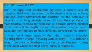
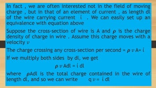
- Magnetic fields can be produced by electric currents in wires, as discovered by Oersted in 1820.
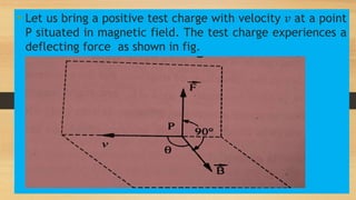
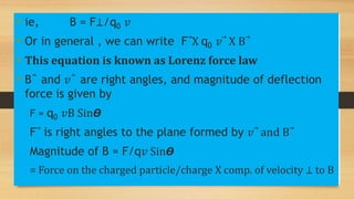
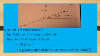
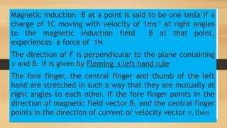
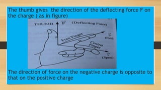
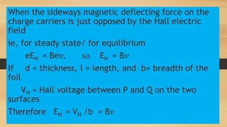
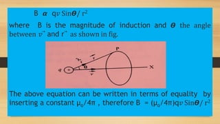
- Magnetic induction B is defined based on the force experienced by a moving charge in a magnetic field.
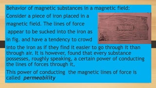
- Materials can be classified as ferromagnetic, paramagnetic, or diamagnetic based on their behavior in magnetic fields. Permeability and susceptibility quantify a material's response to magnetic fields.