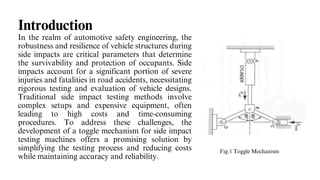
Dr T Thimmaiah Institute of Technology
(Affiliated to Visvesvaraya Technological University Belgaum)
2023 -2024
DEPARTMENT OF MECHANICAL ENGINEERING
KISHORE H (1GV21ME404)
PRASANTH J ( 1GV21ME406)
SANJAY P (1GV21ME408)
SATHISH N (1GV21ME409))
Modeling and Numerical Analysis of Toggle Mechanism for Side
Impact Testing Machine
PRESENTED BY:
UNDER THE GUIDANCE OF:
Dr. Manjunatha Babu N S
Associate Professor & HOD
PROJECT ON
Introduction
In the realm of automotive safety engineering, the
robustness and resilience of vehicle structures during
side impacts are critical parameters that determine
the survivability and protection of occupants. Side
impacts account for a significant portion of severe
injuries and fatalities in road accidents, necessitating
rigorous testing and evaluation of vehicle designs.
Traditional side impact testing methods involve
complex setups and expensive equipment, often
leading to high costs and time-consuming
procedures. To address these challenges, the
development of a toggle mechanism for side impact
testing machines offers a promising solution by
simplifying the testing process and reducing costs
while maintaining accuracy and reliability.
Fig.1 Toggle Mechanism
Objectives and Methodology
Fig.2 Objectives of the Project Fig.3 Methodology
Principal and constraint functions
Fig.4 Principal and constraint functions
Modelling
Cam profile
Spring
Cylinder and
cam follower
arrangements
Guide ways
Design of cam profile
Cam profile: here the type of cam profile used
is snail drop cam. The cam made of cast iron
1.
Hardness, Toughness, Ductility, Elasticity,
The design of cam is to rise the follower up to
2.
6cm.when the follower rises up to 6cm and
sudden falls takes place. lifting the follower
from
3.
0 to 300 degree and dwell period is 60 degree.
These are the design dimension of cam profile.
4.
Fig.5 CAM motion
Cylinder and spring arrangement
Fig.6 Spring and Cylinder
Table.1 Spring Parameters for Different Materials
Design of links
Link 1 is constrained at x direction and has a motion only in y direction
Link 2 and 3 are constrained at y direction and has a motion only in x direction
Fig.7 Links
Material Selection
Metallic Links (Bars): Material: Aluminium Reasoning: Aluminium is chosen for its lightweight
properties, making it easier to handle and assemble the machine components. Additionally, aluminium
offers good strength-to-weight ratio and corrosion resistance, suitable for the application's requirements.
Cams: Material: Cast Iron Reasoning: Cast iron is selected for its high hardness, toughness, and wear
resistance properties, which are essential for withstanding the repeated contact and sliding motion
between the cam and the follower. These properties ensure the durability and longevity of the cam
component.
Springs: Material: Music Wire Reasoning: Music Wire is preferred for its excellent elastic properties,
allowing the spring to deform and return to its original shape repeatedly without permanent deformation.
This property is crucial for the spring to store and release energy efficiently during the testing process.
Table.2 Material Properties
FEA Analysis with Aluminium
FEA Analysis with Mild Steel
FEA Analysis with Cast Iron
FEA Analysis with Copper
Results
Table.3 FEA Results
The present work was mainly focused on toggle mechanism and its working principle. Based on the
literature review and research works carried out by various authors for different application.
Like rock crushing, our work was totally involved the conceptual design of the toggle based side
impact testing machine and its implementation in future. The work was initially started with the
study on design parameter to decide tentative dimension of the element used for side impact testing
machine.
The dimensions are chosen as per the specific standard dimension, the respective components were
created using solid edge software and old model was constituted through assembly. The model
which created will be subjectto finite elementanalysis in order to test it adequacy through stress
induced over each part in future. Later, the model will fully developed through fabrication and
tested for validation.
Conclusion
Our future scope of work involves:
Fabrication of the model followed by the testing for different
trials.
Development of the actual prototype model.
Scope of Future Work
Thanks

Modeling and Analysis of Toggle Mechanism

  • 1.
    Dr T ThimmaiahInstitute of Technology (Affiliated to Visvesvaraya Technological University Belgaum) 2023 -2024 DEPARTMENT OF MECHANICAL ENGINEERING KISHORE H (1GV21ME404) PRASANTH J ( 1GV21ME406) SANJAY P (1GV21ME408) SATHISH N (1GV21ME409)) Modeling and Numerical Analysis of Toggle Mechanism for Side Impact Testing Machine PRESENTED BY: UNDER THE GUIDANCE OF: Dr. Manjunatha Babu N S Associate Professor & HOD PROJECT ON
  • 2.
    Introduction In the realmof automotive safety engineering, the robustness and resilience of vehicle structures during side impacts are critical parameters that determine the survivability and protection of occupants. Side impacts account for a significant portion of severe injuries and fatalities in road accidents, necessitating rigorous testing and evaluation of vehicle designs. Traditional side impact testing methods involve complex setups and expensive equipment, often leading to high costs and time-consuming procedures. To address these challenges, the development of a toggle mechanism for side impact testing machines offers a promising solution by simplifying the testing process and reducing costs while maintaining accuracy and reliability. Fig.1 Toggle Mechanism
  • 3.
    Objectives and Methodology Fig.2Objectives of the Project Fig.3 Methodology
  • 4.
    Principal and constraintfunctions Fig.4 Principal and constraint functions
  • 5.
    Modelling Cam profile Spring Cylinder and camfollower arrangements Guide ways
  • 6.
    Design of camprofile Cam profile: here the type of cam profile used is snail drop cam. The cam made of cast iron 1. Hardness, Toughness, Ductility, Elasticity, The design of cam is to rise the follower up to 2. 6cm.when the follower rises up to 6cm and sudden falls takes place. lifting the follower from 3. 0 to 300 degree and dwell period is 60 degree. These are the design dimension of cam profile. 4. Fig.5 CAM motion
  • 7.
    Cylinder and springarrangement Fig.6 Spring and Cylinder Table.1 Spring Parameters for Different Materials
  • 8.
    Design of links Link1 is constrained at x direction and has a motion only in y direction Link 2 and 3 are constrained at y direction and has a motion only in x direction Fig.7 Links
  • 9.
    Material Selection Metallic Links(Bars): Material: Aluminium Reasoning: Aluminium is chosen for its lightweight properties, making it easier to handle and assemble the machine components. Additionally, aluminium offers good strength-to-weight ratio and corrosion resistance, suitable for the application's requirements. Cams: Material: Cast Iron Reasoning: Cast iron is selected for its high hardness, toughness, and wear resistance properties, which are essential for withstanding the repeated contact and sliding motion between the cam and the follower. These properties ensure the durability and longevity of the cam component. Springs: Material: Music Wire Reasoning: Music Wire is preferred for its excellent elastic properties, allowing the spring to deform and return to its original shape repeatedly without permanent deformation. This property is crucial for the spring to store and release energy efficiently during the testing process. Table.2 Material Properties
  • 10.
  • 11.
  • 12.
  • 13.
  • 14.
  • 15.
    The present workwas mainly focused on toggle mechanism and its working principle. Based on the literature review and research works carried out by various authors for different application. Like rock crushing, our work was totally involved the conceptual design of the toggle based side impact testing machine and its implementation in future. The work was initially started with the study on design parameter to decide tentative dimension of the element used for side impact testing machine. The dimensions are chosen as per the specific standard dimension, the respective components were created using solid edge software and old model was constituted through assembly. The model which created will be subjectto finite elementanalysis in order to test it adequacy through stress induced over each part in future. Later, the model will fully developed through fabrication and tested for validation. Conclusion
  • 16.
    Our future scopeof work involves: Fabrication of the model followed by the testing for different trials. Development of the actual prototype model. Scope of Future Work
  • 17.