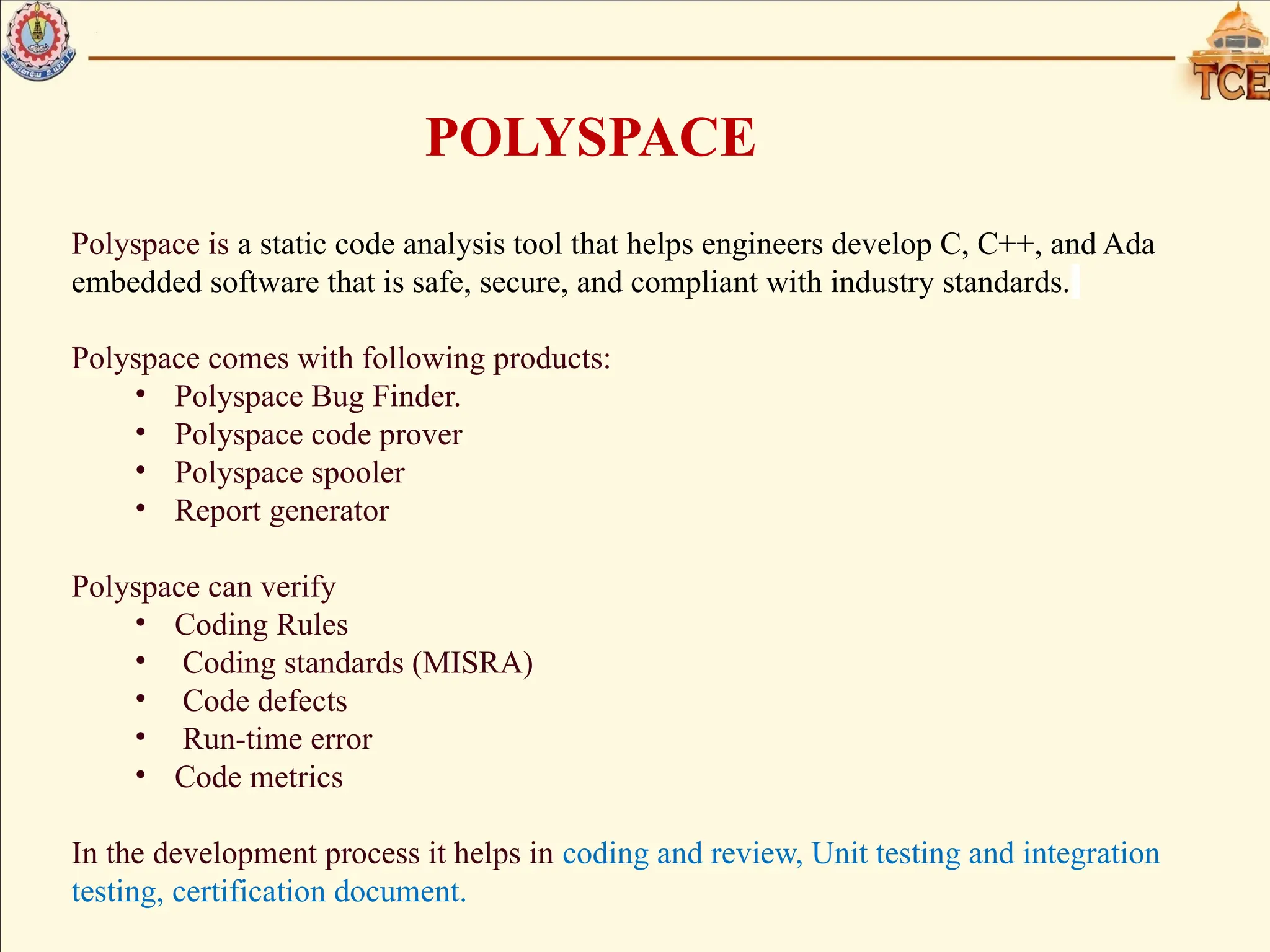
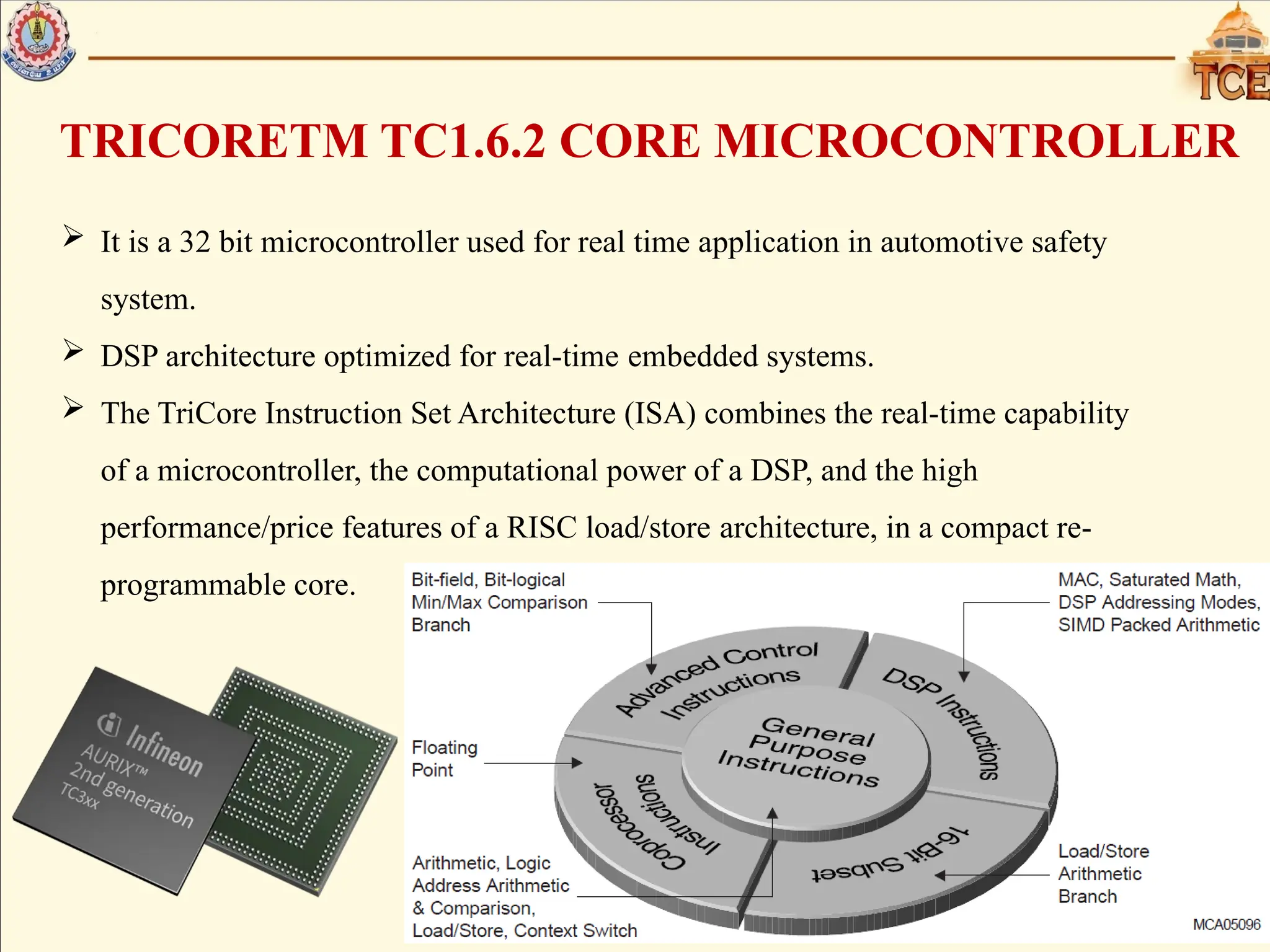
The document discusses static analysis in programming, highlighting its importance in early bug detection and code quality through tools like Polyspace and adherence to MISRA coding guidelines. It outlines the features of the TriCore TC1.6.2 microcontroller, including its architecture for real-time applications and its trap handling system categorized by various classes. Additionally, it details the process of trap handling, distinguishing between synchronous and asynchronous traps, and the specific actions taken when a trap occurs.


![TRAP HANDLING IN INFINEON ARCHITECTURE
Trap occurs due to the following results in the microcontroller
• Non-Maskable Interrupt(NMI)
• Instruction Exception
• Memory Management Exception
• Illegal access
Traps are always active.
There are 8 different classes of traps Each trap has its own trap handler
accessed through the trap vector.
Each trap class has a trap identification number[TIN].
When a trap occurs, a trap identifier is generated by hardware. The trap
identifier has two components:
• The Trap Class Number (TCN) used to index into the trap vector table.
• The Trap Identification Number (TIN) which is loaded into the data register
D[15] of 32 bytes.](https://image.slidesharecdn.com/20d035jaisikareview3ppt-240823094346-53257a41/75/MISRA-and-Polyspace-Guideline-and-Trap-handlng-pptx-6-2048.jpg)


![WORKING OF TRAP HANDLING SYSTEM
INITIAL SETUP:-
The Upper context is saved It refers to preserving the state of the processor or system
before handling an exception or trap.
It involves saving relevant registers, flags, and other context information.
The return address in A[11] is updated.
The TIN is loaded into D[15]
The stack pointer in A[10] is set to the Interrupt Stack Pointer (ISP) when the processor
was not previously using the interrupt stack (in case of PSW.IS = 0). The stack pointer
bit is set for using the interrupt stack:PSW.IS = 1.
The I/O mode is set to Supervisor mode: PSW.IO=10B
The current Protection Register Set is set to 0: PSW.PRS = 000B.
The Call Depth Counter (CDC) is cleared, and the call depth limit is set for 64:
PSW.CDC = 0000000B.
Call Depth Counter is enabled, PSW.CDE = 1.](https://image.slidesharecdn.com/20d035jaisikareview3ppt-240823094346-53257a41/75/MISRA-and-Polyspace-Guideline-and-Trap-handlng-pptx-10-2048.jpg)
![SETUP WHEN THE TRAP OCCURS,
When the trap occurs The hardware generates the TCN and the TIN.
TCN- Trap Class Number
TIN-Trap Identification Number.
BTV [Base Trap Vector] register has the base address of the Trap vector
table spaced with 32 bytes of trap handler or Trap service routine[TSR].
TCN is left shifted by 5 bit and ORd with BTV register which gives the
address of the particular trap handler address for the respective trap.
Respective Trap vector Registers are updated
• Base Trap Vector Table Pointer (BTV)
• Program Synchronous Error Trap Register (PSTR)
• Data Synchronous Error Trap Register (DSTR)
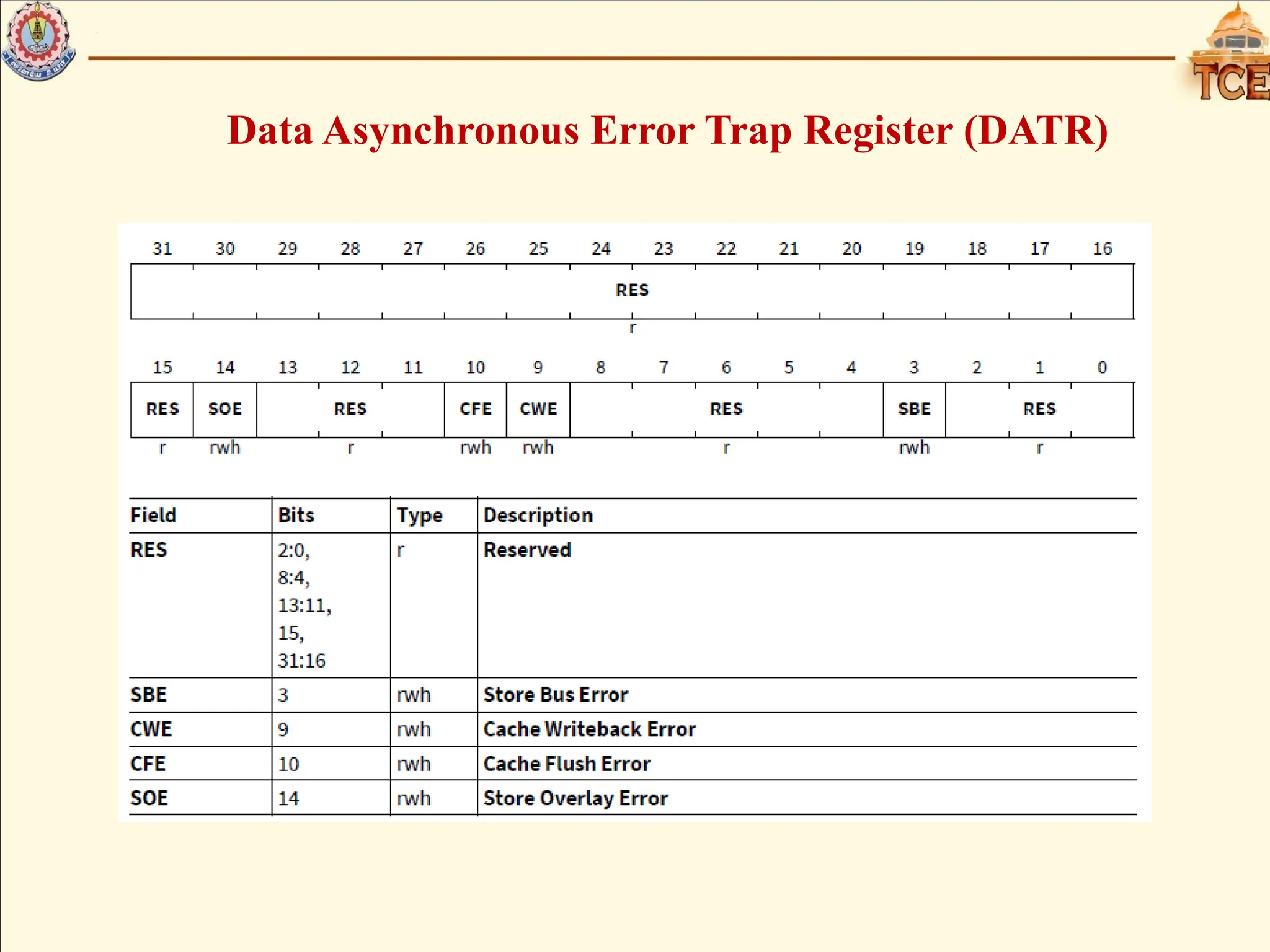
• Data Asynchronous Error Trap Register (DATR)
• Data Error Address Register (DEADD)](https://image.slidesharecdn.com/20d035jaisikareview3ppt-240823094346-53257a41/75/MISRA-and-Polyspace-Guideline-and-Trap-handlng-pptx-11-2048.jpg)


![1. SIH2025-IDEA-Presentation-Format[1].pptx](https://cdn.slidesharecdn.com/ss_thumbnails/1-251204091914-b1bb69d5-thumbnail.jpg?width=640&height=640&fit=bounds)


