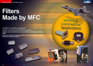
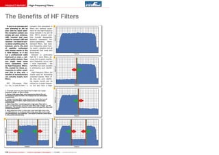
1. MFC is a manufacturer that specializes in high-frequency filters for applications between 5Hz and 50GHz, including filters for the C band segment.
2. High-frequency filters are mostly used to eliminate unwanted interfering signals on neighboring frequencies that can negatively impact receivers and systems. Filters allow filtering out unused frequency ranges carrying interference.
3. The document provides examples of different types of filters, including low-pass, high-pass, band-pass, and band-rejection filters, and how they work to filter signals above or below certain cutoff frequencies.
This document summarizes high-frequency filters produced by MFC for applications in the C band. It discusses how MFC produces specialized filters to prevent interference, particularly from WiMAX signals. It provides examples of new high-frequency filters MFC has developed for the C band, including filters that eliminate WiMAX and radar interference to ensure uninterrupted C band reception.
This document summarizes high-frequency filters produced by MFC. It discusses how high-frequency filters can eliminate unwanted interference signals by allowing only certain frequency bands to pass through. It provides examples of using high-pass, low-pass, band-pass and band-rejection filters. Key applications mentioned include using filters for satellite systems, cable TV networks to separate channels, and reducing interference between signals like DVB and LTE. The document also introduces two new C-band filters recently launched by MFC for satellite applications.
This document discusses high-frequency filters and their benefits. It provides examples of how different types of filters work, including high-pass filters, low-pass filters, band-pass filters, and band-rejection filters. It also describes common applications of these filters, such as eliminating interference, providing separate frequency bands to different receivers, and preventing certain customers from accessing premium cable channels. Key parameters for filters are also defined, including attenuation, bandwidth, cut-off frequency, and insertion loss.
This document discusses vibration signal filtering. It introduces fast Fourier transforms and digital filtering as two primary methods used today to filter digitized vibration measurement values. It describes the main types of vibration signal filters: low-pass filters which allow low frequencies to pass but block high frequencies; high-pass filters which do the opposite; band-pass filters which allow a band of frequencies between high and low cut-off limits to pass; and band-stop filters which block a band of frequencies. Figures are provided to illustrate how each filter type influences the frequency spectrum of a noise signal.
Frequency hopping spread spectrum (FHSS) works by rapidly switching a carrier among many frequency channels, using a pseudorandom sequence known to both transmitter and receiver. The transmitter hops from one frequency to another, transmitting short bursts of information on each channel in turn. The receiver hops in synch to receive the signals. This makes the signal resistant to interference and jamming as an eavesdropper would need to know the hop sequence to intercept the entire message coherently.
Direct sequence spread spectrum (DSSS) spreads data over a wide frequency band by combining the data with a redundant bit sequence called a chipping code. It can transmit at 1, 2, 5.5, and 11 Mbps using different encoding and modulation schemes. Barker coding maps each data bit to an 11-bit sequence for 1-2 Mbps using DBPSK or DQPSK. Complementary code keying maps groups of data bits to unique 8-bit sequences for 5.5-11 Mbps using DQPSK phase shifts. DSSS occupies a 22 MHz band but can tolerate some interference due to its processing gain from spreading the signal.
This document discusses spread spectrum modulation techniques. It begins with an introduction and explains that spread spectrum is a technique where a signal is transmitted over a wider bandwidth than the original signal. It then describes two major spread spectrum techniques: frequency hopping spread spectrum (FHSS) and direct sequence spread spectrum (DSSS). The document outlines the advantages of spread spectrum including resistance to jamming, reduced interference, and security. It also discusses applications of spread spectrum such as wireless communications and Bluetooth.
spread spectrum in digital communicationNidhi Jain
This document discusses spread spectrum communication techniques. It explains that spread spectrum spreads a signal's bandwidth much wider than the minimum required to transmit the information being sent. This is done by modulating the signal with a pseudorandom code that is known to both the transmitter and receiver. The document covers direct sequence spread spectrum and frequency hopping spread spectrum, and discusses their advantages like interference rejection, multipath protection, and ability for multiple users to access the same spectrum.
Understanding RF Fundamentals and the Radio Design of Wireless NetworksCisco Mobility
The document discusses an advanced session that focuses on understanding radio frequency fundamentals and design of wireless networks, covering topics like 802.11 radio hardware, antenna basics, interpreting antenna patterns, distributed antenna systems, survey tools, and lessons learned from challenging wireless deployments in various environments. The session aims to provide a deep-dive understanding of the radio frequency aspects of wireless LAN design and deployment that are often overlooked. Certain topics related to security, density, location services, and management will not be covered in this session.
Distance Measurements using Ultra Wide-Band (UWB)Iqbal Hossain
This thesis examines distance measurement using ultra wideband technology. It discusses UWB applications, regulation, bandwidth properties, and modulation techniques. It then describes single band and multiband UWB modulations. Position estimation parameters such as time of arrival are also covered. Finally, the thesis presents a two way ranging algorithm based on time of arrival for distance measurements and experimental ranging results.
The document discusses the Frequency-Hopping (FH) PHY used in 802.11 wireless networks. It describes key aspects of FH transmission including frequency slots, time slots, and hopping patterns. It also covers Gaussian Frequency Shift Keying (GFSK) modulation, the FH PHY Convergence Procedure (PLCP) for framing data, and the Frequency-Hopping PMD Sublayer for the 1Mbps and 2Mbps FH PHYs. Regulatory domains for hopping sequences are also discussed.
This document provides an overview of spread spectrum technologies including frequency hopping spread spectrum (FHSS) and direct sequence spread spectrum (DSSS). It defines spread spectrum, describes how data is modulated at different rates using DSSS, explains FHSS and DSSS in detail, and lists factors that impact wireless signal performance. Key aspects covered include the FCC regulations for unlicensed use of spread spectrum in the 2.4GHz band, how DSSS spreads and encodes data across multiple frequencies, and how FHSS rapidly hops between frequencies to transmit information.
Frequency-hopping spread spectrum (FHSS) is a communication scheme where the transmitter and receiver switch between different frequencies according to a known standard. FHSS provides robust communication that is resistant to noise, interference, and multipath effects. It allows multiple networks to operate simultaneously without interfering with each other. FHSS also provides security benefits without additional cost due to the unpredictable hopping between frequencies. Common applications of FHSS include military communications systems and small business radios.
Data Communications,Data Networks,computer communications,multiplexing,spread spectrum,protocol architecture,data link protocols,signal encoding techniques,transmission media
This document discusses frequency hopping in wireless communication systems. It begins by explaining that in frequency hopping systems, each call hops between a defined set of frequencies to reduce the impact of poor signal quality on any single frequency. This provides frequency diversity and averages out interference. The document then discusses various types of frequency hopping including baseband and synthesizer hopping. It also covers topics like why frequency hopping is used, factors like multipath fading and interference, and specifications of frequency hopping systems including hopping sequences, mobile allocation lists, and fractional loading.
Spread spectrum technologies use bandwidth more efficiently than narrowband by spreading signals across more frequencies. Direct-sequence spread spectrum (DSSS) encodes each bit as a sequence of chips, allowing higher data rates like 1 Mb/s with DBPSK and 2 Mb/s with DQPSK modulation. Complementary code keying (CCK) encodes blocks of bits as codes, enabling rates up to 11 Mb/s. Orthogonal frequency-division multiplexing (OFDM) uses subcarriers modulated with techniques like BPSK, QPSK, and 16-QAM to achieve rates from 9 Mb/s to 54 Mb/s. However, the wider channels of spread spectrum mean fewer non-overlapping channels are available and interference must be
Brief Introduction to Spread spectrum TechniquesAnil Nigam
There are two main types of spread spectrum multiple access techniques: frequency hopped multiple access (FHMA) and direct sequence multiple access (DSMA). FHMA involves transmitting digital data on different carrier frequencies in a pseudorandom pattern, while DSMA multiplies a message signal by a pseudorandom spreading signal with a much higher chip rate. Code division multiple access (CDMA) is another name for DSMA. Both techniques allow multiple users to transmit simultaneously on the same frequency band.
Frequency hopping spread spectrum (FH-SS) is a type of spread spectrum technique where the available channel bandwidth is divided into a large number of frequency slots arranged continuously. A transmitted signal occupies one or more of the available frequency slots, with the frequencies selected pseudo-randomly based on the output of a pseudo-noise generator. There are two types of FH-SS: slow FH-SS where one or more data bits are transmitted within one hop, and fast FH-SS where one data bit is divided over multiple hops. FH-SS provides advantages like improved interference rejection, code division multiplexing for CDMA, secure communication, and increased capacity and spectral efficiency. It is used in military communication systems, satellite communication,
Weak-Signal Radio Communications for Bitcoin Network ResilienceEngin Karabulut
This document discusses using weak-signal high frequency (HF) radio communications to increase resilience of the Bitcoin network. HF radio can provide long-range broadcast without relying on internet infrastructure, allowing censorship-resistant participation and more diverse connections. The document describes using the ionosphere to reflect radio signals over long distances, digital modulation techniques suitable for noisy radio channels, and a messaging protocol for transmitting Bitcoin data over radio frames. Future work areas include improving modulation schemes and testing long-distance communication capabilities.
The document discusses and compares two approaches for underground object detection using ultra-wideband radar: surface-based radar techniques and borehole radar techniques. Surface-based radar uses wave reflection and attenuation for object registration, while borehole radar only uses wave reflection. Borehole radar provides twice the underground space observation of surface radar with the same system dynamic range. Both techniques allow computerized tomography processing and differ mainly in how deep the boreholes need to be. The document also presents examples of using these techniques for tunnel detection, including with transmitters and receivers on the surface or in vertical boreholes along a border.
Application note signal_generator_spectral_purityS.c. Lu
This document discusses spectral purity and its importance for signal generators. It defines spectral purity as the inherent stability of a signal over time. Short-term stability is the greater concern and is affected by noise and fluctuations. The document outlines common ways to measure spectral purity, including single-sideband phase noise and spurious levels. It explains how poor spectral purity in signal generators can negatively impact receiver measurements by obscuring signals or making receivers appear worse than they are. Strict spectral purity is important for applications like testing narrowband receivers and using signal generators as local oscillators.
The document discusses DSSS and HR/DSSS techniques used in 802.11 wireless networks. It describes how DSSS spreads RF energy over a wider frequency band and how the original 802.11 DSSS PHY specified data rates of 1 Mbps and 2 Mbps. It then summarizes how the 802.11b standard introduced higher data rates of 5.5 Mbps and 11 Mbps using complementary code keying modulation and a shortened PLCP frame format.
This document outlines an RF fundamentals course taught in 3 modules. Module 1 covers basics of RF including frequency, amplitude, wavelength, phase, and polarization. It also discusses transmission line fundamentals. Module 2 discusses RF communication systems, modulation techniques, and RF design. Module 3 covers wireless technologies like Bluetooth, WiFi, and cellular standards. The course provides assignments on topics like wavelength calculation and transmission line speed calculation in different materials. It also explains dBm calculations and concepts like signal to noise ratio, gain and loss.
This document discusses spread spectrum techniques. It begins with a brief history, noting that spread spectrum was invented in the 1940s as a way to prevent enemy detection of radio signals, and gained popularity due to its resistance to jamming. The document then provides an overview of spread spectrum systems, classifications (direct sequence, frequency hopping, time hopping), applications (resistance to interference and jamming, security, CDMA), and comparisons of techniques and their advantages/disadvantages.
The document is a test report for the Fulan ST7111 HDTV receiver. It has the following key points:
1) The Fulan ST7111 receiver has an online platform called "Spark" developed by Fulan that allows for direct customer support while the receiver is in use.
2) The receiver is small, easy to handle, and has connections for HDMI, digital audio, composite video, and a USB port for external storage.
3) Fulan has addressed an irritating issue where one remote can control all of a manufacturer's devices by allowing their remote to switch between different receivers with the push of a button.
The document summarizes a test signal generator produced by WORK Microwave called the Handheld Satcom Test Source. It can generate signals from 50-180 MHz and 950-2150 MHz with adjustable power levels and is used to test high-frequency converters and measure intermodulation signals and compression points. The generator has two independent synthesizers, rechargeable batteries, and connects to a computer via USB to control sweeps and measurements through easy-to-use software. It provides a robust and portable solution for precision high-frequency testing.
The AB IPBox 9900HD is a powerful satellite and multimedia receiver with two DVB-S2 tuners. It runs the open-source Enigma2 operating system, giving it extensive customization options. Key features include numerous video and audio connections, support for common conditional access modules, and an advanced channel listing and favorites system. Its powerful hardware allows for future expansion through additional plugins and applications.
Globalsat, a Chinese OEM receiver manufacturer, is opening a new production facility that will increase its annual production capacity to 8 million units. It plans to double its sales to $150 million in 2011 by expanding into new markets in Europe and North America. The company was founded in 2004 and now employs over 100 engineers for research and development. It produces receivers for satellite TV, terrestrial TV, and IPTV, and will begin distributing products under its own brand name in 2012.
The document discusses the Open IPTV Forum (OIPF) standard for internet-based TV applications. It notes that OIPF aims to establish a global standard to stimulate growth in the IPTV market. The standard incorporates existing technologies and specifications to create open, end-to-end IPTV specifications. It addresses application enablers and definitions to ensure interoperability across platforms and independence from specific devices or middleware. OIPF is already being used in large test deployments in Singapore and Taiwan.
ELNET is a large digital TV wholesaler and retailer located in Iceland that supplies products ranging from small DVB meters to large DVB transmitters. The company believes in both terrestrial and satellite DVB reception. ELNET services Iceland's low population that is spread across a large geographic area, requiring a high number of transmitters. The company expects fiber-optic products to gain popularity as their prices become competitive with coaxial cable systems. ELNET was established in 1982 and remains ready to service Iceland's digital TV needs into the future.
The document summarizes several topics related to digital television broadcasting and IPTV:
1) Many countries are transitioning from analog to digital TV broadcasting, freeing up transmission channels that will be used by mobile operators for data services and IPTV.
2) IPTV delivered over these high-speed wireless networks will allow anyone to become a broadcaster without needing authorization or infrastructure, lowering the barrier to entry.
3) The document advertises companies that offer generators and satellite internet services to enable this new era of wireless IPTV broadcasting.
The document summarizes a test report of the Jaeger HD+ 2011 HDTV receiver, which is optimized for receiving HD channels in Germany that use the new HD+ encryption standard. Key points:
- The receiver was developed by Doebis, a German wholesale dealer, to receive HD versions of major commercial channels encrypted with HD+
- HD+ allows broadcasters to encrypt HD channels and control how and when content can be viewed or recorded (e.g. restricting fast forwarding of ads)
- The Jaeger HD+ 2011 features an HD+ smart card slot and decrypts HD+ channels for viewing upgraded SD versions of commercial broadcasts
- Access to HD+ channels is free for one year then requires a
DOEBIS is a German satellite wholesaler that expanded during the 2008 economic crisis by investing in and growing their sales force. While other companies scaled back, DOEBIS opted for a counter strategy that has paid off with expected sales increases of 25% in 2010 and 10% in 2011. DOEBIS added the TOPFIELD and STRONG brands to their product portfolio and saw good sales results. They primarily serve large online dealers domestically and internationally.
The document discusses high-frequency filters produced by MFC. It provides details on the types of filters MFC produces, their uses, and benefits. Key points:
- MFC specializes in filters between 5 Hz and 50 GHz for applications like satellite reception systems, cable headends, and satellite uplinks.
- Their filters are particularly useful for eliminating interference in crowded frequency bands like the C-band. Filters allow specific frequency ranges to pass while blocking others.
- The document outlines different filter types (low-pass, high-pass, band-pass, band-reject) and how they work to filter out unwanted signals above or below cutoff frequencies.
MFC manufactures high-frequency filters for applications between 5 Hz and 50 GHz. Their filters are used to eliminate unwanted signals and interference, which can negatively impact satellite and cable TV systems. Different types of filters like high-pass, low-pass, and band-pass filters allow only certain frequency bands to pass through while blocking others. This helps provide interference-free reception and prevents signal leakage in networks. MFC's catalog provides details on various filter models specialized for applications like C-band satellite and cable TV systems.
This product report summarizes high-frequency filters manufactured by MFC. It discusses how MFC produces highly specialized filters for applications such as WiMAX to prevent interference. It also explains how high-pass and low-pass filters can be combined to replace separate frequency filters. The report provides details on the benefits of HF filters, describing how they eliminate unwanted signals on certain frequencies to prevent interference and equipment malfunctions.
This product report discusses high-frequency filters produced by MFC for applications in the C band. MFC produces various types of filters including band-pass filters to allow only desired frequency ranges to pass through. The report highlights new filters from MFC, including filters designed to eliminate interference from WiMAX and radar signals in the C band. MFC filters are used in satellite reception systems, cable networks, and other applications to block unwanted frequencies and prevent interference between signals.
Vibration signal filtering involves removing unwanted frequencies from signals. There are two main digital filtering methods: Fast Fourier Transform and digital filtering. Filters are named based on the frequencies they pass or block, including low pass, high pass, band pass, and band stop filters. Low pass filters allow low frequencies to pass while attenuating high frequencies. High pass filters have the opposite effect, allowing high frequencies to pass. Band pass filters allow a band of frequencies to pass while blocking others. Band stop filters attenuate a band of frequencies but pass others. Filters have various applications in electronics, communications, and other fields.
Your Ultimate Guide to Designing Analog Filters - Welcome to OXELTECH.pdfaud Scarlet
In contrast to a digital circuit, which requires a signal to be one of two discrete levels, an Analog circuit uses a continuous, variable signal that is called an Analog signal.
Design of a microstrip bandpass filter Tauseef khan
This document describes the design of a microstrip bandpass filter with a center frequency of 3 GHz and 20% fractional bandwidth. It uses quarter wavelength shorted stub resonators designed on AWR Microwave Office simulation software. The filter design achieves less than 4dB insertion loss within the passband, which ranges from 2.712 GHz to 3.268 GHz. The stub filter architecture makes the design more compact and easier to realize compared to coupled line filters, although it requires impedances that can be difficult to implement in practice. In conclusion, the microstrip bandpass filter design meets the specified requirements and its performance is simulated and verified using the software.
The design of an Antenna system for a Cell Extender site needs to take into account the following specific factors:
a) The systems input and output frequencies can be relatively close.
b) The Cell (output) channels are fixed, but the Donor (RF Link) radios are frequency agile, as the channel can vary from call to call (to follow the Donor sites Traffic Channel allocation).
This Document is specially written to assist in Cell Extender antenna system design. As such, it is assumed that the reader has a good understanding of standard antenna system design techniques such as filter, multi coupler and other combiner technologies, as issues discussed in this Document only relate to specific Cell Extender application aspects. Matters such as elimination of Intermod products etc are not addressed in the context of this Document - please refer to normal common standard techniques and practices for these issues.
Please note that this Document provides design "Rules" only. Experience in antenna system design remains indispensable in actual practice!
This document discusses filters and their uses in radio communications. It begins by explaining how filters are used to select desired signals and reject undesired ones. It then covers the basics of different filter types including low-pass, high-pass, band-pass and band-stop filters. Specific examples of filters are provided like crystal filters and cavity filters. Placement of filters and their effect on impedance matching is also discussed.
In signal processing, a filter is a device or process that removes some unwanted components or features from a signal. Filtering is a class of signal processing, the defining feature of filters being the complete or partial suppression of some aspect of the signal. Most often, this means removing some frequencies or frequency bands. However, filters do not exclusively act in the frequency domain; especially in the field of image processing many other targets for filtering exist. Correlations can be removed for certain frequency components and not for others without having to act in the frequency domain. Filters are widely used in electronics and telecommunication, in radio, television, audio recording, radar, control systems, music synthesis, image processing, and computer graphics.
Satellite communications systems allow communication between two points on Earth via satellites. A signal is transmitted from an earth station to a satellite, which then relays the signal to another earth station. Satellites provide large area coverage and can bypass terrestrial networks. They are used for voice calls, television, radio, internet access, and more. Higher frequency bands like Ku-band provide more flexibility than C-band but are more susceptible to rain fade. Modern systems use modulation techniques like QPSK and 8-PSK along with error correction coding to optimize bandwidth use on satellites.
This document contains a project report submitted by three students, Kul Vaibhav, Manish Kumar, and Munna Kumar, for their Bachelor of Technology degree. The report describes their project on RF filter design conducted under the guidance of their professor, Avishek Das. The report includes an introduction to electronic filters and RF filters. It then discusses different types of filters including Butterworth, Bessel, and Chebyshev filters. The report also covers the design of bandpass filters and their applications.
This document discusses band pass filters that are constructed using a combination of low pass and high pass filters integrated with operational amplifiers. It provides equations to calculate key filter parameters like resonance frequency, bandwidth, and cutoff frequencies based on resistor and capacitor values. Simulation results show that as the near infrared operating wavelength increases, the filter capacitance increases, resistance decreases, resonance frequency and cutoff frequencies decrease, and gain increases. The document examines these filter characteristics over a wide range of parameters.
The document discusses filters and attenuators. It describes filters as electrical circuits that can modify, reshape, or reject unwanted frequencies from an electrical signal, passing only desired signals. Filters are classified as low-pass, high-pass, band-pass, and band-stop based on which frequency bands they allow to pass. Characteristic impedance is real in pass bands and imaginary in stop bands. Constant-k and m-derived filters including low-pass, high-pass, band-pass, and band-stop filters are also covered qualitatively. Attenuators are discussed qualitatively as being symmetrical or asymmetrical.
The document discusses various digital modulation techniques used in wireless communication systems. It explains the concepts of frequency-shift keying (FSK), minimum-shift keying (MSK), Gaussian minimum-shift keying (GMSK) used in GSM. It also discusses phase-shift keying (PSK) techniques like binary PSK (BPSK), quadrature PSK (QPSK) and differential QPSK (DQPSK). Further, it introduces quadrature amplitude modulation (QAM) and hierarchical modulation used in DVB-T. The document also explains spread spectrum techniques like direct-sequence spread spectrum (DSSS) and frequency-hopping spread spectrum (FHSS), discussing their advantages and applications in cellular networks
This document discusses parameters for designing digital television broadcast networks. It covers topics such as calculating transmitter requirements based on field strength, receiver sensitivity and modulation. It also discusses fixed and portable antenna reception considerations. The document compares network designs like single frequency networks (SFN), multi-frequency networks (MFN) and hybrid networks. It provides details on synchronization requirements for SFNs and challenges like interference from mobile networks. The document was presented at the Caribbean Digital Broadcasting Switchover Forum 2012 in Trinidad and Tobago.
RLC circuits can be used as filters to selectively pass or block ranges of frequencies. There are four main types of filters: low-pass filters which allow low frequencies to pass and block high frequencies, high-pass filters which do the opposite, band-pass filters which allow a band of frequencies to pass while blocking those outside the band, and band-stop filters which block a band of frequencies while passing others. Each type of filter can be made by different combinations of resistors, inductors and capacitors in series or parallel configurations, with the center frequency and bandwidth determined by the component values. Filters have many applications including use in audio systems, wireless transmitters and receivers, and imaging processing.
Vibration signals can be filtered using various filter types to isolate different frequency bands. Active filters use op-amps and transistors while passive filters use inductors, capacitors, and resistors. Filter types include low-pass, high-pass, band-pass, and band-stop filters based on the frequencies allowed. Filter designs like Butterworth, Chebyshev, and elliptic provide different frequency responses. Spectrum analysis separates a signal into its frequency components using filters. Fast Fourier transforms allow real-time analysis by rapidly converting time signals to frequency spectra.
The document provides an overview of radio receiver principles including:
1) It describes tuned radio frequency (TRF) receivers, superheterodyne receivers, and double superheterodyne receivers.
2) It explains concepts like selectivity, image frequency rejection, and automatic gain control (AGC).
3) Key aspects of receivers like sensitivity, selectivity, signal-to-noise ratio, and fidelity are defined.
The summary captures the high-level topics covered in the document around different types of radio receivers and important receiver concepts in 3 sentences as requested.
Filters are used to selectively pass or block ranges of frequencies in electronic circuits. The main types are low-pass filters, which pass low frequencies and block high frequencies; high-pass filters, which do the opposite; band-pass filters, which pass a band of frequencies; and band-stop or band-reject filters, which block a band of frequencies. Filters can be built using passive components like resistors, capacitors, and inductors in configurations like RC, RL, RLC, pi, and T networks or can use active components like op-amps. The document discusses examples and circuit diagrams of each main filter type.
The document tests and reviews the Moi Plus streaming box by TBS, which acts as a central DVB receiver that can distribute TV and radio signals via a home network to multiple devices. Key features include its small size, ability to be located remotely from TVs, support for wireless and wired networking, and integration of tuners. It comes preinstalled with the Tvheadend software, which allows automatic channel scanning, creation of customized channel lists for each user, electronic program guide functionality, and recording of content to external USB drives connected to the Moi Plus box. The review concludes the Moi Plus and Tvheadend together provide a versatile whole-home digital TV solution.
The Tekniksat optical distribution system can deliver 4 satellite signals and 1 terrestrial signal to hundreds of receivers with equal signal quality at all outputs. It uses an optical transmitter to convert the signals to a single optical signal, an optical splitter to divide the signal, and an optical multiswitch to convert it back and distribute to subscribers. Testing showed the system maintained sufficient gain and only minimally impacted signal quality even when splitting the signal across 320 receivers. It is recommended for efficiently distributing signals to a large number of subscribers.
The document reviews the Satlink WS6979HD signal analyzer. It has a high-resolution screen, HDMI output, long battery life, and supports DVB-S2 and DVB-T2. The device has comprehensive measurement and analysis functions for satellite and terrestrial signals. It also functions much like a standard satellite receiver, with features like an editable channel list and electronic program guide. Overall, the Satlink WS6979HD is a fully-featured, high-quality signal meter suitable for both professional and amateur use.
The document summarizes a mobile app called Satbeams that helps users align satellite dishes. It allows users to check if a satellite is receivable at their location and see satellite footprints offline. The app displays satellites on a virtual sky and calculates azimuth and elevation. It relies on an extensive satellite database but lacks daily frequency lists. Overall, the app provides a valuable tool for easily determining satellite reception and positioning dishes.
The document discusses the Logitech Harmony Smart Control system, which allows a smartphone or tablet to replace all original remote controls. It utilizes a hub connected to devices via infrared and Bluetooth. The hub also connects to the local WiFi network to handle commands from the Harmony app. The app can control up to eight devices at once and remembers pre-programmed command sequences. Gestures on the app allow for easy control of functions like volume. The system was able to successfully control all devices tested, including receivers, Blu-Ray players, an Apple TV, and gaming consoles.
Jim Edstein operates a large satellite reception system from the remote mountains of Taiwan to provide streaming services around the world. He first set up systems for expats to watch channels from home, then began streaming channels over the Internet in 2006. With fast, unlimited fiber Internet access in his area, he is now able to stream over 1000 TB of data per month to 90 point-to-point customers and host equipment for 7 additional customers. Operating from a small town in Taiwan, he distributes international TV channels globally via Internet streaming.
TELE-audiovision is a digital TV industry publication established in 1981 that is headquartered in Munich, Germany. It is published by TELE-audiovision Magazine GmbH and edited by Alexander Wiese. The publication has a readership of over 350,000 digital TV professionals worldwide. The current issue discusses the shift from coaxial cable to fiber optic technology for satellite signal distribution. Fiber optic distribution eliminates limitations of cable length and number of distribution points. It also means each user has access to the full satellite bandwidth at all times. The editor notes that while coaxial cable faces issues like signal attenuation related to frequency, fiber optic technology is not impacted by these factors.
The document discusses a DekTec DTA-2115 PCI Express card that can generate test signals for terrestrial, cable, and satellite receivers using a single PC card. It has an extremely wide frequency range from 32 MHz to 2186 MHz and supports virtually all digital modulation standards. This makes it very useful for testing receivers and troubleshooting reception issues. The card's software allows the user to adjust various signal parameters like modulation, frequency, error injection and signal quality to simulate real-world conditions.
The document provides a review of the SATFINDER 5 HD Slim handheld satellite meter from Alpsat Elektronik. It is small, lightweight device that features a high-resolution color display, integrated battery, and ability to simultaneously measure up to four transponders. The meter has a comprehensive pre-programmed database of satellites, transponders and channels. It allows for fine-tuning of dish alignment through features like cross-polarization measurement and constellation diagrams. The review concludes the SATFINDER 5 HD Slim is an extremely responsive meter for evaluating satellite signals.
The document is the May-June 2015 issue of TELE-audiovision Magazine, the world's leading digital TV industry publication. The issue includes test reports on new satellite equipment from companies like TEKNIKSAT, SATLINK, TENOW, and SATBEAMS. It also features articles on the growing use of fibre-optic technology for signal distribution, a profile of a Taiwanese satellite enthusiast, an overview of notable satellite uplink stations, and the history of TELE-audiovision magazine.
The document describes the Spaun Sparos 711 professional meter for digital TV. It has a 10-inch touchscreen with high resolution and is optimized for antenna installers and technicians. The meter has a rugged metal case and offers simultaneous measurements of transponder signals. It can measure DVB formats along with ASI, HDMI and other connectivity. The large touchscreen and intuitive interface make it easy to use right out of the box. An included transport case presents a professional image for installers.
The document tests and reviews the MKTech CB200 HD dual tuner meter. It is a small, lightweight, and easy to use meter that allows installers to simultaneously monitor signals and parameters for two different inputs. It has a clear LCD screen, intuitive interface, built-in database of satellites and transponders, and features like automatic satellite detection that make it suitable for professional installation and troubleshooting tasks. The review finds that while small in size, the meter has strong performance and many useful features for installers.
1) Haenlein Software develops and sells PVR software that allows users to record and edit digital TV programs and easily transfer recordings between different receivers.
2) Started in 1999 as a side project, Haenlein Software is now the owner's full-time business, employing 3 people working from home.
3) Their software works with over 800 different receiver models, has been translated into many languages, and is sold internationally through distributors and partnerships with receiver manufacturers.
1. GlobalInvacom's FibreIRS family improves satellite signal distribution using fiber optic cables instead of coaxial cables, allowing signal splitting and longer cable runs with minimal loss.
2. The new FibreIRS O2E optical-to-electrical converter, combined with the FibreIRS ODU optical amplifier, can regenerate and amplify signals after splitting, improving signal quality beyond the original source.
3. In tests, the combination of FibreIRS O2E and ODU provided amplification to restore signal strength after splitting 32 ways, while further improving modulation error ratio, demonstrating its ability to multiply outputs from a single LNB while enhancing signal quality.
The Formuler F1 is a triple-tuner HD receiver that provides fast channel changing and search functions. It can be installed with various operating systems, including OpenPLI, OpenATV, and HDMU. The receiver features a versatile channel search, excellent electronic program guide, and the ability to record multiple channels simultaneously. Overall, the Formuler F1 delivers speed and a fun user experience, as its name and F1 designation would suggest.
The document provides a test report of the Fernsehfee 2.0, an intelligent TV receiver developed by TC Unterhaltungselektronik AG for German-speaking markets. Some key features of the Fernsehfee 2.0 include an ad blocker, optimized program guide for German channels, recording function, and built-in WiFi for connecting to networks. It also functions as a web TV box thanks to its Android operating system. The Fernsehfee 2.0 learns users' viewing preferences through an account system and recommends content it thinks they will enjoy based on ratings and past viewing behavior.
EICO is an antenna wholesaler and retailer located in Reykjavik, Iceland that has been in business since 1979. It sells over 400 satellite dishes per year, with 85cm dishes being the most popular for receiving signals from ASTRA. EICO also distributes signals using GlobalInvacom's fiber-optic system to over 100 apartments. While EICO previously installed MMDS systems, that technology is expected to be discontinued in Iceland. Overall, EICO remains at the forefront of technology for receiving TV signals in Iceland.
This document provides information about TELE-audiovision Magazine, a digital TV trade publication established in 1981. It is published by TELE-audiovision Magazine GmbH based in Munich, Germany. Alexander Wiese is the publisher and editor-in-chief. The magazine is published in both print and digital formats and covers topics related to digital TV technology and devices, with a focus on products that utilize multiple tuners in the latest issue.
This document is the March-April 2015 issue of TELE-audiovision, a digital TV trade magazine published since 1981. The issue includes test reports on new products such as a triple-tuner HD receiver, a dual tuner signal meter, and an amplifier that improves signal quality. It also has articles on a software developer in Germany and a satellite equipment wholesaler in Iceland, as well as information on the magazine's global readership and a history of TELE-audiovision.
The document tests and reviews the Titanium Satellite C1W-PLL LNBF. It was tested on an offset dish in southern France and found to have excellent reception quality, with a gain of up to 6.2 dBμV. The C1W-PLL uses PLL technology to provide a very stable signal lock, even for difficult signals like low symbol rates or high FEC carriers. It is recommended as a best bargain for C-band enthusiasts due to its high performance and low price.
1. PRODUCT REPORT
High-Frequency Filters
Filters
Made by MFC
• HF filters for all kinds of applications
• hugely successful in the C band filter segment
• highly specialised filters to prevent WiMAX interference, among
others
• high-pass filters and low-pass filters can be combined to replace
frequency-separating filters
170 TELE-audiovision International — The World‘s Largest Digital TV Trade Magazine — 1
1-12/2013 — www.TELE-audiovision.com
www.TELE-audiovision.com — 1
1-12/2013 — TELE-audiovision International — 全球发行量最大的数字电视杂志
171
2. PRODUCT REPORT
High-Frequency Filters
The Benefits of HF Filters
If you’re an average end
user planning to set up
your own Ku band satellite reception system you
simply get your antenna,
LNB, receiver and coax
cable to connect LNB and
receiver – no need to worry about anything else. If,
however, you’re the kind
of satellite enthusiast
who always wants to dig
a little deeper, or if you
run a professional cable
head-end or even a satellite uplink station, then
you might need some
more equipment, such
as high-frequency filters.
The market for those accessories is rather small,
and this is why only a
handful of manufacturers
can actually supply such
filters.
MFC
(Microwave
Filter
Co., Inc.) is one of them – a
company that specialises in
filters and optional equipment for the high-frequency
range between 5 Hz and 50
GHz. MFC’s product portfolio includes waveguides,
dielectric resonators, frequency-separating
filters,
standard filters, load resistors (frequently called ‘dummy loads’), adapters and all
accessories that come with
those items.
Demand is particularly
high for C band filters, because this is where interference frequently occurs and
– more importantly – the
right filter can work wonders
in eliminating such interference.
High-frequency filters are
mostly used for eliminating
unwanted signals. More often than not, such interfering signals cannot only be
noticed on a single frequency, but also have a nega-
1
2
3
1. A sample spectrum: the signal level is high over a great
frequency range, no filter is used.
2. Using a high pass filter: only frequencies above the cutoff frequency pass the filter, low frequencies are attenuated
substantially.
3. Using a low pass filter: only frequencies under the cut-off
frequency pass the filter, high frequencies are attenuated
substantially.
4. Band-Pass filter: combining both a high pass filter with a
lower cut-off frequency and a low pass filter with a higher cut-off
frequency. The result is that the centre band will pass the filter with
minimal attenuation.
5. Band-Rejection filter: in this case a low pass filter with a low
cut-off frequency is combined with a high pass filter with a high
cut-off frequency are combined. The result is that the centre band
is attenuated substantially.
4
5
172 TELE-audiovision International — The World‘s Largest Digital TV Trade Magazine — 1
1-12/2013 — www.TELE-audiovision.com
3. ■ Example with a UHF filter of a pay TV operator: The left picture shows the whole CATV
spectrum without any filter. The right picture shows the result of using a low pass filter
with a cut-off frequency of 296 MHz.
■ The new catalogue by MFC gives an extensive overview of all available filters made by MFC. The
catalogue can also be downloaded directly from their website: www.microwavefilter.com
174 TELE-audiovision International — The World‘s Largest Digital TV Trade Magazine — 1
1-12/2013 — www.TELE-audiovision.com
tive impact on neighbouring
frequencies. In addition, receivers and other active elements within the system are
at risk of malfunctioning due
to interference.
The trick now is to filter
out those unused frequency
ranges that carry the interfering signals.
Existing signals can be filtered in a number of different ways. For one, it is possible to filter out signals above
and/or below a certain specified frequency. Low-pass and
high-pass filters are used to
that end. A low-pass filter
allows all frequencies below
the cut-off frequency, while a
high-pass filter lets through
all frequencies above a set
cut-off frequency. Unwanted
frequencies that are outside
the cut-off frequencies are
highly attenuated, whereas
the target frequency range
comes through with minimal
attenuation.
Now if you combine a highpass filter with low cut-off
frequency and a low-pass
filter with high cut-off frequency it is even possible to
only allow a single frequency
range through the filter setup. The correct term for such
a configuration is band-pass
filter.
If, on the other hand, a
low-pass filter is used in conjunction with a high-pass filter that has a higher cut-off
frequency, only the centre
frequency space is filtered
and what we get is a socalled reject filter.
Then again, what’s the use
of all those filters? To start
with, they allow providing
individual frequency bands
to different receivers without those receivers having to
share frequency bands. SCR
(Single Cable Routing) distribution setups, for instance,
make use of this approach,
with up to eight receivers
having independent access
to all satellite channels via a
single cable that is led from
one wall outlet to the next.
In such a configuration, each
receiver is assigned a dedicated frequency band with
a central router modulating
the required transponder
onto the corresponding frequency band.
Network operators, on
the other hand, use filters
in analog CATV networks
as well to make sure customers with less expensive
subscriptions cannot receive
premium channels. Those
channels are usually transmitted on higher frequencies
and a sealed low-pass filter
at the transfer point just outside the house or apartment
prevents those subscribers
from watching channels they
don’t pay for.
The most important reason for installing filters,
however, can be found in the
fact that neighbouring signals are generally prone to
interference from each other. Unlike the number of different applications and uses
sharing the same resources,
the frequency range cannot be increased at random
and has to be accepted as
a given, with all its capacity
constraints. Even very strict
technical regulations and
mandatory frequency charts
cannot do much in terms of
interference prevention.
A prominent everyday example is interference in the
DVB-T/T2 and ATSC range
caused by LTE signals. As
far as the regulator is concerned,
all
applications
should work side by side
in the frequency spectrum
without doing harm to each
other by using only those
frequencies that have been
specifically sat aside for each
application.
We all know too well, however, that in the real world
it’s often an entirely different story.
Generally speaking, highfrequency interference can
by caused by a number of
different phenomena.
As far as receivers are
concerned:
• Interference from neighbouring frequencies
• Interference in the IF
(intermediate frequency)
• Interference in the LO
(local oscillator) frequency
Interference can also be
caused at the transmitting
end:
• In addition to the desired emission frequency,
neighbouring frequencies
may be affected by unwanted emissions that are
caused by the modulator.
• Harmonics emissions
• Interference caused by
intermodulation
When it comes to selecting an appropriate filter it
is paramount to understand
all parameters given by the
manufacturer. Listed below
are the most important of
them:
• Attenuation
Attenuation is measured
in decibels and indicates
the level by which the input
signal is decreased. To find
out the exact attenuation
the signal level is measured
first at input and then again
at output, with the resulting
difference in decibels (dB)
being the achieved attenuation.
• Bandwidth
This parameter indicates
the bandwidth of a bandpass filter, that is to say the
frequency range that passes
through the filter with a relative insertion loss of 3 dB or
less.
• Cut-off frequency
This is the frequency that
triggers either the high-pass
New High-Frequency Filters by MFC
for the C-Band
Model 18253 - C-Band (INSAT) Transmit Reject Filter
• This TRF provides deep rejection of the transmit band with minimal effect on the
receive band.
• Ideal for INSAT and other Region-Specific Receive Applications
• Alternate Flange Configurations are Available Upon Request
Pass band
4.5 - 4.8 GHz (C-INSAT Downlink)
Insertion Loss
0.50 dB Max
VSWR
1.30:1 Max
Reject Band
6.725 - 7.025 GHz (C-INSAT Uplink)
Rejection
80 dB Min
Operating Temperature Range
-10°C to +60°C
Flanges CPR229G
Dimensions
3.95” x 3.88” x 2.75” (100mm x 98mm x 70mm)
Finish
Gloss White Lacquer
Model 18323 - C-Band (INSAT) Receive Reject Filter
• Same as before but rejection of the receive (Downlink) band
Passband
6.725 - 7.025 GHz
Insertion Loss
0.10 dB Approx.
VSWR
1.22:1 Max
Reject Band
4.5 - 4.8 GHz
Rejection
80 dB Typ
Flanges CPR137/CPR137G
Dimensions
5.00“ x 2.69“ x 1.94“ (127mm x 68mm x 49mm)
Finish
White Lacquer
Model 18506 - Multi-Purpose C-Band Transmit Filter
• This Uplink filter not only rejects the entire receive band (below 4.2 GHz), but
it also rejects transmissions from other potential sources of interference etc., that
RRFs do not.
• Ideal for use in high-density transmit paths, like:
Wireless Services (Point-Multipoint)
4.55 - 4.9 GHz
Maritime & Aeronautical Radio Navigation 4.2 - 5.6 GHz
Broadcast Auxiliary Services
6.95 -7.15 GHz
• Ideal for all “standard band” C-Band Uplink Applications
• Easy bolt-on installation and no power supply required
Passband
5.925 - 6.425 GHz
Passband Loss
0.3 dB Max
Passband Return Loss
17.7 dB Min
Rejection
50 dB Min @ 5.625 GHz
40 dB Min @ 6.725 GHz
Power Rating
400 Watts
Flanges CPR137F
Dimensions
9.50” x 2.69” x 1.94” (241mm x 68mm x 49mm)
Finish
Gloss White Lacquer
www.TELE-audiovision.com — 1
1-12/2013 — TELE-audiovision International — 全球发行量最大的数字电视杂志
175
4. filter or low-pass filter.
• Decibel
This measuring unit gives
the relation between two
signals (P1 and P2) based on
the following equation:
dB = 10 Log10 (P1/P2)
• Insertion loss
Like any other active or
passive element between the
antenna and the receiver/
transmitter the use of a filter causes a certain amount
of overall signal attenuation.
The insertion loss parameter
indicates that attenuation,
which should be as low as
possible (max. 3 dB).
• Phase shift
This parameter indicates
the runtime shift of the signal that is caused by the filter. In general, phase shifts
become more pronounced
with
higher
frequencies,
which means digital signals are more affected than
analog signals.
Problems
in the C Band
WiMAX and radar applications (weather radar, in particular) are major sources of
interference in the C band.
For uninterrupted C band
reception it can therefore
be recommended to use
band-pass filters that only
allow the required frequency
range to pass through.
As far as the C band is
concerned, we have to draw
a line between the standard
C band and the extended C
band. To complicate matters
even further, some regions,
such as Russia for example,
use a slightly different frequency range for the C band.
This means that the actual
frequency band defines the
filter to be used. In recent
years, WiMAX (Worldwide
Interoperatibility for Microwave Access) has become a
source of much frustration.
WiMAX is used for wireless
Internet access in the 2300
MHz, 2500 MHz and 3500
MHz bands and as such has
enormous potential for causing interference in the C
band.
The standard approach in
such a case calls for adding a highly selective bandpass filter, whose frequency
range corresponds to the
local footprint (that is 37004200 MHz, 3400-4200 MHz,
etc.). More recently, however, WiMAX was also launched
in many regions worldwide
in the 3400-3800 MHz frequency band. The resulting
in-band interference in the C
band can no longer be eliminated with the help of conventional band-pass filters,
since signals from WiMAX
transmitters using 3700 MHz
and consequently impacting
the 3700-4200 MHz range,
will still come through with
a standard band-pass filter
that allows all frequencies
between 3700 and 4200 MHz
to pass through. This means
the interfering WiMAX signal is not blocked and such
a filter does not solve the
problem. A special filter is
required in such a scenario
– one that only lets through
signals on frequencies of
3750 MHz and above, for example.
Filters for such high-frequency applications are extremely complex and a lot
of expertise and experience
are necessary for designing state-of-the-art filters.
What’s more, special manufacturing processes must be
adhered to, since we’re not
only talking about the odd
electronic switch or circuit
C-Band
TX(MHz)
RX (MHz)
Standard
5850–6425
3625–4200
Extended
6425–6725
3400–3625
New High-Frequency Filters by MFC
for the C-Band
Model 13961W-I - International (Extended)
C-Band Interference Elimination Filter
• No other filter in the industry provides as much rejection of undesired signals in
such a compact size.
• Eliminates WiMAX, RADAR and virtually all other sources of out-of-band interference
• Lightweight - Aluminium Construction
• Ready to install between LNB & feed horn
Pass band
3.6 - 4.2 GHz
Pass band Loss
0.5 dB Typ @ centre band
0.5 dB Typ roll-off @ band edges
Pass band VSWR
1.5:1 Typ
Group Delay Variation
8 ns Max
Rejection
45 dB Typ @ 3.55 GHz / 4.25 GHz
55 dB Typ @ 3.45 GHz / 4.35 GHz
70 dB Typ @ 3.40 GHz / 4.40 GHz
Flanges
CPR229G (Input), CPR229F (Output)
Length
5.49“ (13.9 cm)
Weight
1.125 lbs. (0.51 Kg)
Finish
Gloss White Lacquer
here. High-frequency signals
are transmitted even without electronic conductors
in place, which is why such
filters mainly consist of hollow conductors in the form of
waveguides.
When you look at one of
those filters as an absolute
layperson, it’s almost impossible to tell where and how
the filter can be integrated
into the existing reception
system. The answer is surprisingly
straightforward:
right at the antenna between
the feed horn and the LNB/
LNA.
Filters of this kind are
mainly produced with computer-assisted
milling
in
combination with special
CAM software which calculates the exact milling movements. As far as the C band
is concerned, MFC is the
leading manufacturer world-
176 TELE-audiovision International — The World‘s Largest Digital TV Trade Magazine — 1
1-12/2013 — www.TELE-audiovision.com
wide of filters for eliminating
interference. No other company even comes close to
MFC and its comprehensive
portfolio of filters for radar,
WiMAX or any other signal
causing interference.
All it takes is a look at recently introduced filters,
which MFC has started to
produce not too long ago
to see what this company is
made of. And of course TELEaudiovision readers can take
a first-row seat when some
of MFC’s major new developments take centre stage
below.
For filters in the C band
there’s no way around MFC,
a company specialising in the
development and production
of those special purpose filters, and which therefore is
in a position to offer products with top-notch specifications.