Download to read offline


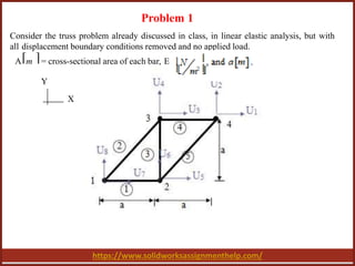
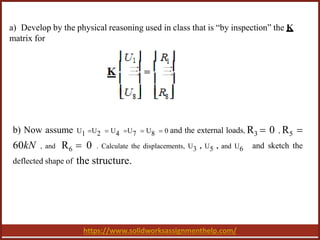
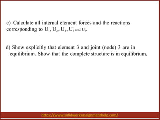
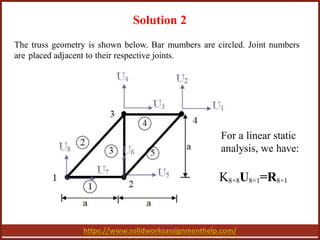
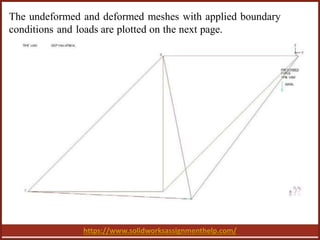
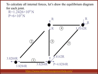
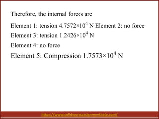
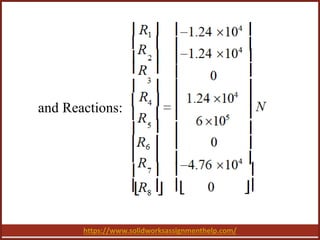


The document discusses finite element analysis (FEA) in the context of a truss structure, emphasizing the analysis of displacement and internal forces under specific boundary conditions. It outlines the mathematical formulation for the stiffness matrix and equilibrium conditions, providing calculations for displacements and internal element forces. The conclusion highlights the importance of FEA in understanding structural mechanics and its applications in engineering design.


![Lecture truss [compatibility mode]](https://cdn.slidesharecdn.com/ss_thumbnails/lecturetrusscompatibilitymode-160126134009-thumbnail.jpg?width=640&height=640&fit=bounds)


