SlideShare a Scribd company logo
1
EXPERIENCE DURING “AS-BUILT” SERVICES IN INDUSTRIAL
PROJECTS USING LASER 3D TECHNOLOGY
by Eng° Marcos Guandalini
Alezi Teodolini Consultoria3D
2
• Alezi Teodolini Consultoria 3D presentation
• Experience during “As-built” services execution in a oil and
gas refinery in Brazil, followed by 3D modeling using
VANTAG PDMS (Plant Design Management System)
• CAE model procedure and an example of a successful case.
• Conclusions
3
Alezi Teodolini Consultoria3D is a
HEZOLINEM Group´s company,
located in São Paulo, Brazil.
Hezolinem was the pionner of survey
equipment deal and it is a well-known
company in all Brazilian market since
1975.
The Alezi Teodolini Consultoria3D new
business area has 5 years and already
have committed team with 25
professionals for the AS-BUILT projects.
Alezi Teodolini headquarters in São Paulo
4
Company:
– Consolidation as the best supplier of CAE creation using cloud
points and projects of engineering in PDS or PDMS platforms
– Maintaining the data entirety and the speed during the project
model execution with high quality.
Presentation:
– Demonstrating the method of our job using CAE model in PDMS;
– Presenting the cloud points and the Modeling in PDMS of
Brazilian refinery.
5
Offered Products
CLOUD POINTS FOR
CLASH DETECTION
CAE/CAD MODELS
DIMENSIONAL
CONTROL
6
7
Project experience during As-Built services
in a Brazilian refinery followed by PDMS modeling.
The Project
8
Refinery - Summary
The Refinery:
• The most complete
refinery of PETROBRÁS
system;
• Located: Brazil
• Area of 13km2;
• Production of lubricant,
diesel, GLP, nafta,
kerosene, etc.
9
Refinery – Contract
Resume
The Agreement:
• The biggest project was done using 3D Laser Scanner;
• A total of 500 milions points;
• 361 Stations, 3800 piping and 250 equipment;
• Complete PDMS Model and engineer as-built plants.
• Contract Time Frame: 13 months – start: 12/12/2006.
• The agreement total value : U$ 900 000,00.
• It is considered as a reference project in Brazil.
The main object of our contract
with the refinery
10
Material and Survey
Time
Materials used in the Project
– 02 units of 3D Laser Scanners GS200;
– 01 Total Station;
– 02 Notebooks;
– 10 Flat targets;
– 15 Reference spheres.
Site Surveying duration:
– 3 months.
Station number:
- 361 stations.
Grid
- 10 mm at 10 meters for all 360°
scanning
.
Total of the points collected:
– 500 millions.
11
Planning/Execution:
– The estimative was:
• A total of 1,5 hours per 360 degrees
station;
• The use of 7 stations per day during
the site surveying based on
photography's,
• Plants and technical visits in the
project area;
• 3 months with one scanner.
– It was spent:
• 1,5 hours per 360 degrees station;
• The production averages was only 4
stations per day due to the problems
occurred with the batteries and
equipment temperature;
• It was finished in 3 months using 2
equipment.
Field Crew – working in the Refinery
Survey Direction
12
Field Crew
• 1 Leader Enginering – 8 months
• 2 Surveyors – 3 months
• 2 Assistants – 3 months
• 1 Driver/Assistant – 3 months
• 1 Senior Piping – 8 months
Field Crew – working in the Refinery
13
Survey Direction
Survey
– Flat and spherical targets
were used in order to help
during the consolidation
process;
– Total Station: Conventional
surveying in order to put
cloud points in the correct
coordinate system of site
surveying plant;
– Consolidation or register.
Field Crew– working in the refinery
14
Site Surveying
Description
Targets were located in
order to position the cloud
points in the refinery
coordination system using
the refinery landmarks;
361 stations were scanned
to obtain cloud points in
real color.
Field Crew – working in the Refinery
15
Collected cloud points making easy
the scanned data interpretation
Photo taken using the
scanner in the same position
of the cloud point surveying.
Cloud Points
Collection
16
Cloud Points
Collection
The biggest cloud points done with a 3D Laser Scanner – 500 millions of points
17
A project specialist was hired
in order to update all
documentation regarding to
1210 unit: 95% concluded.
18
Field Advantage Points
using GS200:
– The scanner weight;
– The equipment does a complete
360º using a half of the time with
reference to HDS3000;
– The color of the cloud points helps
during the object identification;
– The scanner transportation is easy
because of its backpack. Field Crew – working in the Refinery
19
Field Work Difficulties
Battery:
– Weight : 14 Kg ;
– Autonomous : 4 h ;
– Transport difficult
Temperature
– Due to the high temperature
the equipment stopped to work
several times during one day
Series GS
– Good conditions are essential
for the scanner work.
– Field vertical view is restricted
to 60°
Field Crew – working in the Refinery
20
Cloud
Points/Consolidation
Difficulty
• More than 500.000.000 points to
manage;
• RWS is able to open only 60.000
points.
Result
• 500.000.00 points in the same
coordinate system.
PC Configuration
• Pentium D 3.0 Ghz;
• 2.0 GB RAM memory;
• Graphic Card 256 Mb. Field Crew – working in the Refinery
21
Cloud
Points/Consolidation
• This kind of project has a lot of
points and being its
consolidation very complex;
• The control of the surveying
work points is very important.
Alezi Teodolini´s office – São Paulo, Brazil
22
Cloud
Points/Consolidation
PROCEDURE
• The total area was divided up
among 35 sub-areas;
• 3 teams working during 2
months:
– 30% using cloud based on
registration tool of RWS and
70% using spheres and targets
– In order to put the cloud points
in the real coordinate system, it
was made a topographic
surveying to collect flat target
coordinates.
23
Modeling/Engineering
team
• 1 Leader Engineer
• 1 PDMS Manager - 8 months
• 1 Senior project professional – 5
months
• 8 Professionals of CAD Modeling–
8 months
• 2 CAD designers – 3 months
Alezi Teodolini´s office – São Paulo, Brazil
24
The Modeling Team
• Our team is trainned according to the following stages:
– First Stage:
• Professional with notions of the basic CAD
• 3Dipsos training = 2 months
• Piping/structure and general industrial concepts training =
2months
• 15 lines are produced in 3Dipsos per day.
– Second Stage
• PDMS training = 3 months
• PI&D concept training = 1 month
• 15 lines are produced in PDMS/PDC per day.
25
3Dipsos – Modeling
Alowed
• We made a series of modeling demos in order to
genarate a PDMS model two years before closing the
agreement.
• After the modeling demos, our customer has
approved 3Dipsos software.
A part of our agreement with
the customer
26
Office Job Direction
STEP 1: Team planning and definition per subjects (Piping, Equipment,
Metallic, Civil and Electrical);
Modeling team = 8 professionals
Office in São Paulo – Alezi Teodolini Office in São Paulo – Alezi Teodolini
27
Working with Specs
STEP 2: PDMS Management of data base configuration,
users and password creation;
STEP 3: SPEC importation including customer specifications;
Standard Catalogues (SPECS):
Possible to import and work with
diferent specs
On the same project
28
Cloud points
STEP 4: Cloud point segmentation;
Raw Data of the Cloud Points
Cloud Points divided up on
separated groups for modeling.
29
Senior Piping Project and
PDMS Administrator
STEP 5:
The senior project professional after
the field surveying updated the P&ID
in order to give the real information
to the modeling team.
SPEC´s and catalogs creation using
the PDMS software.
Senior Project Professional – working in
Refinery
30
Modeling with the SPECS
for PDMS
Associating a segmented
structure with a reconized
semi- automatic spec
If the pipe is isolated by the
temperature, it will be possible
to model using only the pipe
dimensions.
Creating Branches
associated with catalogs
(SPEC).
31
PDMS interface
STEP 6:
PDMS modeling;
3Dipsos software / PDC (Point
Cloud Data Center) use with
PDMS direct interface;
32
Modeling Tools
– Automatic method use with exclusive modeling tools that improve
the production capacity;
– easypipe® is a cloud points tool that can model all pipe
components without operator interference increasing the
productivity 3 (three) times.
33
Checking the PDMS
Model
STEP 7: Model check and validating during all the modeling process
described before;
34
PDMS Model
STEP 8: Delivery of 3D model in PDMS
•Equipment
•Pipes
•Electrical
•Civil
•Metallic structures
35
We have to up-date the model every month to the customer
Modeling Progress
36
Modeling Progress
62% of the complete job - PDMS Model. Delivery time: March-2008
37
38
39
40
41
Engineering Update
STEP 9: Updated plant generation and delivery (using ADP);
STEP 10: Updated PI&D delivery.
42
3D Laser Scanner used and its
importance during an 3D AS-Built
project
Cloud Points
X
Project
PDS Picture – We will need to delivery the solution
for PDMS.
43
Cloud Points
X
As-built model
PDS Picture – We need to delivery the solution for PDMS.
44
As-Built Company
advantages
• Piping modeling associated to the SPECs offering speedy and
entirety;
• Recognition of automatic structure profiles associated to the charts;
• Modeling time optimization tools as such as: EasyPipe® (automatic
extraction of tubulation), Beam Extraction (automatic extraction of
structures);
• 3D model updated;
• Clash Detection;
• Accuracy of the model.
45
Advantages
Refinary
• Stop time reduction at the refinery;
• Cost and time reduction during the building and assembly;
• Risk simulation possibility;
• Facility and efficiency to the future project development;
• Plants and PI&D up to date;
• Smart models generating automatically the Isometrics and Material
list.
46
Pipe Isometric
47
Piping Plan
48
PI&D
49
Conclusion
• The new 3D Laser Scanner technology allows a CAE
model that shows the real situation in the field, offering
a lot of benefits in the industrial plant management's
day by day ;
• The use of 3Dipsos/PDC software allows to reduce the
modeling time that causes a direct impact in the
project cost ;
• The service cost is irrelevant if compared on its cost-
benefit vantages.
50
Eng. Marcos Guandalini
São Paulo/SP, Brazil
Phone: (55 11) 3868-0825
www.hezolinem.com/consultoria3D
consultoria3D@hezolinem.com

More Related Content

Similar to EXPERIENCE DURING ' AS-BUILT ' SERVICES IN INDUSTRIAL PROJECT USING LASER 3D TECHNOLOGY

Wood Group ODL Dimensional Control
Wood Group ODL Dimensional ControlWood Group ODL Dimensional Control
Wood Group ODL Dimensional Control
Stewart Buchanan
 
3 d designer
3 d designer3 d designer
3 d designer
CADISON
 

Similar to EXPERIENCE DURING ' AS-BUILT ' SERVICES IN INDUSTRIAL PROJECT USING LASER 3D TECHNOLOGY (20)

Instalatii_petroliere_05_EN
Instalatii_petroliere_05_ENInstalatii_petroliere_05_EN
Instalatii_petroliere_05_EN
 
Wood Group ODL Dimensional Control
Wood Group ODL Dimensional ControlWood Group ODL Dimensional Control
Wood Group ODL Dimensional Control
 
Instalatii_petroliere_08_EN
Instalatii_petroliere_08_ENInstalatii_petroliere_08_EN
Instalatii_petroliere_08_EN
 
Visualizing the engineering project lifecycle - Unite Copenhagen
Visualizing the engineering project lifecycle - Unite CopenhagenVisualizing the engineering project lifecycle - Unite Copenhagen
Visualizing the engineering project lifecycle - Unite Copenhagen
 
Instalatii_petroliere_02_EN
Instalatii_petroliere_02_ENInstalatii_petroliere_02_EN
Instalatii_petroliere_02_EN
 
CADISON world Issue-1-2013
CADISON world Issue-1-2013CADISON world Issue-1-2013
CADISON world Issue-1-2013
 
Instalatii_petroliere_07_EN
Instalatii_petroliere_07_ENInstalatii_petroliere_07_EN
Instalatii_petroliere_07_EN
 
Instalatii_petroliere_06_EN
Instalatii_petroliere_06_ENInstalatii_petroliere_06_EN
Instalatii_petroliere_06_EN
 
PMI 3D Laser Scanning (As Built) Services
PMI 3D Laser Scanning (As Built) ServicesPMI 3D Laser Scanning (As Built) Services
PMI 3D Laser Scanning (As Built) Services
 
Instalatii_petroliere_01_EN
Instalatii_petroliere_01_ENInstalatii_petroliere_01_EN
Instalatii_petroliere_01_EN
 
Instalatii_petroliere_04_EN
Instalatii_petroliere_04_ENInstalatii_petroliere_04_EN
Instalatii_petroliere_04_EN
 
Neboneed Farhadi's Experience Portfolio
Neboneed Farhadi's Experience Portfolio Neboneed Farhadi's Experience Portfolio
Neboneed Farhadi's Experience Portfolio
 
Manufacturing Day - Case Study - MacLean Engineering
Manufacturing Day - Case Study - MacLean EngineeringManufacturing Day - Case Study - MacLean Engineering
Manufacturing Day - Case Study - MacLean Engineering
 
Vopak 3D Mapping
Vopak 3D MappingVopak 3D Mapping
Vopak 3D Mapping
 
3D Laser Scaning FPSO Mystras
3D Laser Scaning FPSO Mystras3D Laser Scaning FPSO Mystras
3D Laser Scaning FPSO Mystras
 
3D Laser Scaning FPSO Mystras
3D Laser Scaning FPSO Mystras3D Laser Scaning FPSO Mystras
3D Laser Scaning FPSO Mystras
 
Fikus presentation 2015
Fikus presentation 2015Fikus presentation 2015
Fikus presentation 2015
 
3 d designer
3 d designer3 d designer
3 d designer
 
Piping engineering
Piping engineeringPiping engineering
Piping engineering
 
COMIT March 2017 - Cost Effective Digitisation of Existing Assets
COMIT March 2017 - Cost Effective Digitisation of Existing AssetsCOMIT March 2017 - Cost Effective Digitisation of Existing Assets
COMIT March 2017 - Cost Effective Digitisation of Existing Assets
 

Recently uploaded

RS Khurmi Machine Design Clutch and Brake Exercise Numerical Solutions
RS Khurmi Machine Design Clutch and Brake Exercise Numerical SolutionsRS Khurmi Machine Design Clutch and Brake Exercise Numerical Solutions
RS Khurmi Machine Design Clutch and Brake Exercise Numerical Solutions
Atif Razi
 
Standard Reomte Control Interface - Neometrix
Standard Reomte Control Interface - NeometrixStandard Reomte Control Interface - Neometrix
Standard Reomte Control Interface - Neometrix
Neometrix_Engineering_Pvt_Ltd
 
Laundry management system project report.pdf
Laundry management system project report.pdfLaundry management system project report.pdf
Laundry management system project report.pdf
Kamal Acharya
 
School management system project report.pdf
School management system project report.pdfSchool management system project report.pdf
School management system project report.pdf
Kamal Acharya
 

Recently uploaded (20)

A case study of cinema management system project report..pdf
A case study of cinema management system project report..pdfA case study of cinema management system project report..pdf
A case study of cinema management system project report..pdf
 
Halogenation process of chemical process industries
Halogenation process of chemical process industriesHalogenation process of chemical process industries
Halogenation process of chemical process industries
 
Courier management system project report.pdf
Courier management system project report.pdfCourier management system project report.pdf
Courier management system project report.pdf
 
Explosives Industry manufacturing process.pdf
Explosives Industry manufacturing process.pdfExplosives Industry manufacturing process.pdf
Explosives Industry manufacturing process.pdf
 
Cloud-Computing_CSE311_Computer-Networking CSE GUB BD - Shahidul.pptx
Cloud-Computing_CSE311_Computer-Networking CSE GUB BD - Shahidul.pptxCloud-Computing_CSE311_Computer-Networking CSE GUB BD - Shahidul.pptx
Cloud-Computing_CSE311_Computer-Networking CSE GUB BD - Shahidul.pptx
 
Quality defects in TMT Bars, Possible causes and Potential Solutions.
Quality defects in TMT Bars, Possible causes and Potential Solutions.Quality defects in TMT Bars, Possible causes and Potential Solutions.
Quality defects in TMT Bars, Possible causes and Potential Solutions.
 
Construction method of steel structure space frame .pptx
Construction method of steel structure space frame .pptxConstruction method of steel structure space frame .pptx
Construction method of steel structure space frame .pptx
 
KIT-601 Lecture Notes-UNIT-3.pdf Mining Data Stream
KIT-601 Lecture Notes-UNIT-3.pdf Mining Data StreamKIT-601 Lecture Notes-UNIT-3.pdf Mining Data Stream
KIT-601 Lecture Notes-UNIT-3.pdf Mining Data Stream
 
RS Khurmi Machine Design Clutch and Brake Exercise Numerical Solutions
RS Khurmi Machine Design Clutch and Brake Exercise Numerical SolutionsRS Khurmi Machine Design Clutch and Brake Exercise Numerical Solutions
RS Khurmi Machine Design Clutch and Brake Exercise Numerical Solutions
 
The Benefits and Techniques of Trenchless Pipe Repair.pdf
The Benefits and Techniques of Trenchless Pipe Repair.pdfThe Benefits and Techniques of Trenchless Pipe Repair.pdf
The Benefits and Techniques of Trenchless Pipe Repair.pdf
 
KIT-601 Lecture Notes-UNIT-5.pdf Frame Works and Visualization
KIT-601 Lecture Notes-UNIT-5.pdf Frame Works and VisualizationKIT-601 Lecture Notes-UNIT-5.pdf Frame Works and Visualization
KIT-601 Lecture Notes-UNIT-5.pdf Frame Works and Visualization
 
Standard Reomte Control Interface - Neometrix
Standard Reomte Control Interface - NeometrixStandard Reomte Control Interface - Neometrix
Standard Reomte Control Interface - Neometrix
 
Pharmacy management system project report..pdf
Pharmacy management system project report..pdfPharmacy management system project report..pdf
Pharmacy management system project report..pdf
 
ASME IX(9) 2007 Full Version .pdf
ASME IX(9)  2007 Full Version       .pdfASME IX(9)  2007 Full Version       .pdf
ASME IX(9) 2007 Full Version .pdf
 
Laundry management system project report.pdf
Laundry management system project report.pdfLaundry management system project report.pdf
Laundry management system project report.pdf
 
Arduino based vehicle speed tracker project
Arduino based vehicle speed tracker projectArduino based vehicle speed tracker project
Arduino based vehicle speed tracker project
 
Introduction to Casting Processes in Manufacturing
Introduction to Casting Processes in ManufacturingIntroduction to Casting Processes in Manufacturing
Introduction to Casting Processes in Manufacturing
 
HYDROPOWER - Hydroelectric power generation
HYDROPOWER - Hydroelectric power generationHYDROPOWER - Hydroelectric power generation
HYDROPOWER - Hydroelectric power generation
 
Introduction to Machine Learning Unit-4 Notes for II-II Mechanical Engineering
Introduction to Machine Learning Unit-4 Notes for II-II Mechanical EngineeringIntroduction to Machine Learning Unit-4 Notes for II-II Mechanical Engineering
Introduction to Machine Learning Unit-4 Notes for II-II Mechanical Engineering
 
School management system project report.pdf
School management system project report.pdfSchool management system project report.pdf
School management system project report.pdf
 

EXPERIENCE DURING ' AS-BUILT ' SERVICES IN INDUSTRIAL PROJECT USING LASER 3D TECHNOLOGY

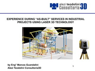
  • 1. 1 EXPERIENCE DURING “AS-BUILT” SERVICES IN INDUSTRIAL PROJECTS USING LASER 3D TECHNOLOGY by Eng° Marcos Guandalini Alezi Teodolini Consultoria3D
  • 2. 2 • Alezi Teodolini Consultoria 3D presentation • Experience during “As-built” services execution in a oil and gas refinery in Brazil, followed by 3D modeling using VANTAG PDMS (Plant Design Management System) • CAE model procedure and an example of a successful case. • Conclusions
  • 3. 3 Alezi Teodolini Consultoria3D is a HEZOLINEM Group´s company, located in São Paulo, Brazil. Hezolinem was the pionner of survey equipment deal and it is a well-known company in all Brazilian market since 1975. The Alezi Teodolini Consultoria3D new business area has 5 years and already have committed team with 25 professionals for the AS-BUILT projects. Alezi Teodolini headquarters in São Paulo
  • 4. 4 Company: – Consolidation as the best supplier of CAE creation using cloud points and projects of engineering in PDS or PDMS platforms – Maintaining the data entirety and the speed during the project model execution with high quality. Presentation: – Demonstrating the method of our job using CAE model in PDMS; – Presenting the cloud points and the Modeling in PDMS of Brazilian refinery.
  • 5. 5 Offered Products CLOUD POINTS FOR CLASH DETECTION CAE/CAD MODELS DIMENSIONAL CONTROL
  • 6. 6
  • 7. 7 Project experience during As-Built services in a Brazilian refinery followed by PDMS modeling. The Project
  • 8. 8 Refinery - Summary The Refinery: • The most complete refinery of PETROBRÁS system; • Located: Brazil • Area of 13km2; • Production of lubricant, diesel, GLP, nafta, kerosene, etc.
  • 9. 9 Refinery – Contract Resume The Agreement: • The biggest project was done using 3D Laser Scanner; • A total of 500 milions points; • 361 Stations, 3800 piping and 250 equipment; • Complete PDMS Model and engineer as-built plants. • Contract Time Frame: 13 months – start: 12/12/2006. • The agreement total value : U$ 900 000,00. • It is considered as a reference project in Brazil. The main object of our contract with the refinery
  • 10. 10 Material and Survey Time Materials used in the Project – 02 units of 3D Laser Scanners GS200; – 01 Total Station; – 02 Notebooks; – 10 Flat targets; – 15 Reference spheres. Site Surveying duration: – 3 months. Station number: - 361 stations. Grid - 10 mm at 10 meters for all 360° scanning . Total of the points collected: – 500 millions.
  • 11. 11 Planning/Execution: – The estimative was: • A total of 1,5 hours per 360 degrees station; • The use of 7 stations per day during the site surveying based on photography's, • Plants and technical visits in the project area; • 3 months with one scanner. – It was spent: • 1,5 hours per 360 degrees station; • The production averages was only 4 stations per day due to the problems occurred with the batteries and equipment temperature; • It was finished in 3 months using 2 equipment. Field Crew – working in the Refinery Survey Direction
  • 12. 12 Field Crew • 1 Leader Enginering – 8 months • 2 Surveyors – 3 months • 2 Assistants – 3 months • 1 Driver/Assistant – 3 months • 1 Senior Piping – 8 months Field Crew – working in the Refinery
  • 13. 13 Survey Direction Survey – Flat and spherical targets were used in order to help during the consolidation process; – Total Station: Conventional surveying in order to put cloud points in the correct coordinate system of site surveying plant; – Consolidation or register. Field Crew– working in the refinery
  • 14. 14 Site Surveying Description Targets were located in order to position the cloud points in the refinery coordination system using the refinery landmarks; 361 stations were scanned to obtain cloud points in real color. Field Crew – working in the Refinery
  • 15. 15 Collected cloud points making easy the scanned data interpretation Photo taken using the scanner in the same position of the cloud point surveying. Cloud Points Collection
  • 16. 16 Cloud Points Collection The biggest cloud points done with a 3D Laser Scanner – 500 millions of points
  • 17. 17 A project specialist was hired in order to update all documentation regarding to 1210 unit: 95% concluded.
  • 18. 18 Field Advantage Points Field Advantage Points using GS200: – The scanner weight; – The equipment does a complete 360º using a half of the time with reference to HDS3000; – The color of the cloud points helps during the object identification; – The scanner transportation is easy because of its backpack. Field Crew – working in the Refinery
  • 19. 19 Field Work Difficulties Battery: – Weight : 14 Kg ; – Autonomous : 4 h ; – Transport difficult Temperature – Due to the high temperature the equipment stopped to work several times during one day Series GS – Good conditions are essential for the scanner work. – Field vertical view is restricted to 60° Field Crew – working in the Refinery
  • 20. 20 Cloud Points/Consolidation Difficulty • More than 500.000.000 points to manage; • RWS is able to open only 60.000 points. Result • 500.000.00 points in the same coordinate system. PC Configuration • Pentium D 3.0 Ghz; • 2.0 GB RAM memory; • Graphic Card 256 Mb. Field Crew – working in the Refinery
  • 21. 21 Cloud Points/Consolidation • This kind of project has a lot of points and being its consolidation very complex; • The control of the surveying work points is very important. Alezi Teodolini´s office – São Paulo, Brazil
  • 22. 22 Cloud Points/Consolidation PROCEDURE • The total area was divided up among 35 sub-areas; • 3 teams working during 2 months: – 30% using cloud based on registration tool of RWS and 70% using spheres and targets – In order to put the cloud points in the real coordinate system, it was made a topographic surveying to collect flat target coordinates.
  • 23. 23 Modeling/Engineering team • 1 Leader Engineer • 1 PDMS Manager - 8 months • 1 Senior project professional – 5 months • 8 Professionals of CAD Modeling– 8 months • 2 CAD designers – 3 months Alezi Teodolini´s office – São Paulo, Brazil
  • 24. 24 The Modeling Team • Our team is trainned according to the following stages: – First Stage: • Professional with notions of the basic CAD • 3Dipsos training = 2 months • Piping/structure and general industrial concepts training = 2months • 15 lines are produced in 3Dipsos per day. – Second Stage • PDMS training = 3 months • PI&D concept training = 1 month • 15 lines are produced in PDMS/PDC per day.
  • 25. 25 3Dipsos – Modeling Alowed • We made a series of modeling demos in order to genarate a PDMS model two years before closing the agreement. • After the modeling demos, our customer has approved 3Dipsos software. A part of our agreement with the customer
  • 26. 26 Office Job Direction STEP 1: Team planning and definition per subjects (Piping, Equipment, Metallic, Civil and Electrical); Modeling team = 8 professionals Office in São Paulo – Alezi Teodolini Office in São Paulo – Alezi Teodolini
  • 27. 27 Working with Specs STEP 2: PDMS Management of data base configuration, users and password creation; STEP 3: SPEC importation including customer specifications; Standard Catalogues (SPECS): Possible to import and work with diferent specs On the same project
  • 28. 28 Cloud points STEP 4: Cloud point segmentation; Raw Data of the Cloud Points Cloud Points divided up on separated groups for modeling.
  • 29. 29 Senior Piping Project and PDMS Administrator STEP 5: The senior project professional after the field surveying updated the P&ID in order to give the real information to the modeling team. SPEC´s and catalogs creation using the PDMS software. Senior Project Professional – working in Refinery
  • 30. 30 Modeling with the SPECS for PDMS Associating a segmented structure with a reconized semi- automatic spec If the pipe is isolated by the temperature, it will be possible to model using only the pipe dimensions. Creating Branches associated with catalogs (SPEC).
  • 31. 31 PDMS interface STEP 6: PDMS modeling; 3Dipsos software / PDC (Point Cloud Data Center) use with PDMS direct interface;
  • 32. 32 Modeling Tools – Automatic method use with exclusive modeling tools that improve the production capacity; – easypipe® is a cloud points tool that can model all pipe components without operator interference increasing the productivity 3 (three) times.
  • 33. 33 Checking the PDMS Model STEP 7: Model check and validating during all the modeling process described before;
  • 34. 34 PDMS Model STEP 8: Delivery of 3D model in PDMS •Equipment •Pipes •Electrical •Civil •Metallic structures
  • 35. 35 We have to up-date the model every month to the customer Modeling Progress
  • 36. 36 Modeling Progress 62% of the complete job - PDMS Model. Delivery time: March-2008
  • 37. 37
  • 38. 38
  • 39. 39
  • 40. 40
  • 41. 41 Engineering Update STEP 9: Updated plant generation and delivery (using ADP); STEP 10: Updated PI&D delivery.
  • 42. 42 3D Laser Scanner used and its importance during an 3D AS-Built project Cloud Points X Project PDS Picture – We will need to delivery the solution for PDMS.
  • 43. 43 Cloud Points X As-built model PDS Picture – We need to delivery the solution for PDMS.
  • 44. 44 As-Built Company advantages • Piping modeling associated to the SPECs offering speedy and entirety; • Recognition of automatic structure profiles associated to the charts; • Modeling time optimization tools as such as: EasyPipe® (automatic extraction of tubulation), Beam Extraction (automatic extraction of structures); • 3D model updated; • Clash Detection; • Accuracy of the model.
  • 45. 45 Advantages Refinary • Stop time reduction at the refinery; • Cost and time reduction during the building and assembly; • Risk simulation possibility; • Facility and efficiency to the future project development; • Plants and PI&D up to date; • Smart models generating automatically the Isometrics and Material list.
  • 49. 49 Conclusion • The new 3D Laser Scanner technology allows a CAE model that shows the real situation in the field, offering a lot of benefits in the industrial plant management's day by day ; • The use of 3Dipsos/PDC software allows to reduce the modeling time that causes a direct impact in the project cost ; • The service cost is irrelevant if compared on its cost- benefit vantages.
  • 50. 50 Eng. Marcos Guandalini São Paulo/SP, Brazil Phone: (55 11) 3868-0825 www.hezolinem.com/consultoria3D consultoria3D@hezolinem.com