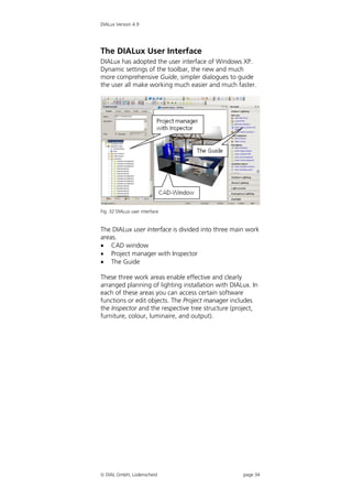
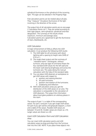
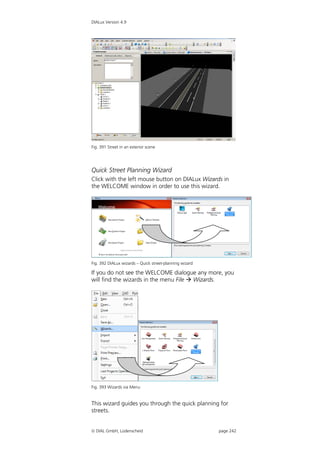
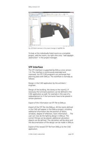
The document provides information about DIALux lighting design software version 4.9, including:
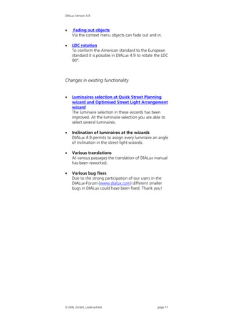
- New features in version 4.9 such as improvements to existing functionality.
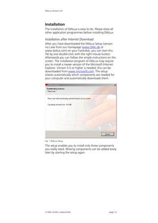
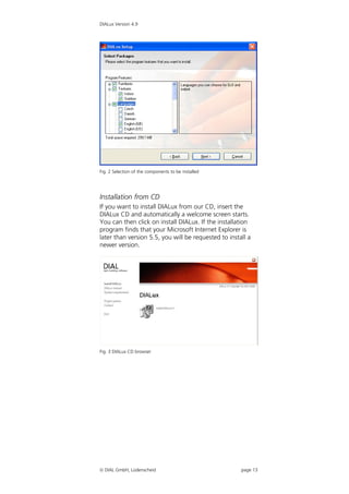
- Instructions for installing DIALux from an internet download or CD.
- An overview of the DIALux user interface and main functions for creating and editing lighting projects, inserting lights, furniture and textures, performing lighting calculations, and generating outputs.
- Information on additional features for tasks like exterior lighting, emergency lighting, and working with standards for road lighting design.
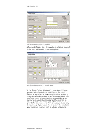
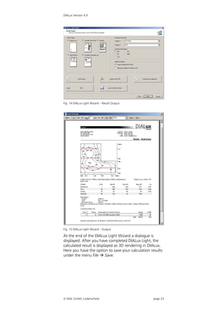
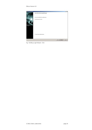
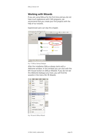
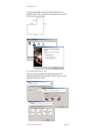
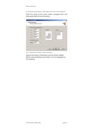
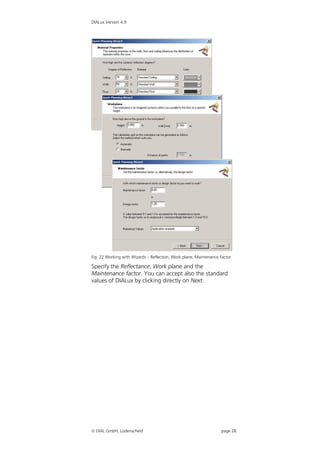
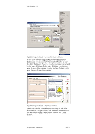
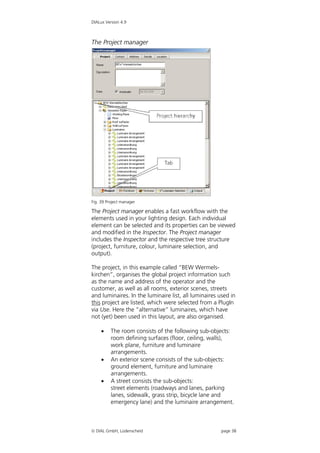
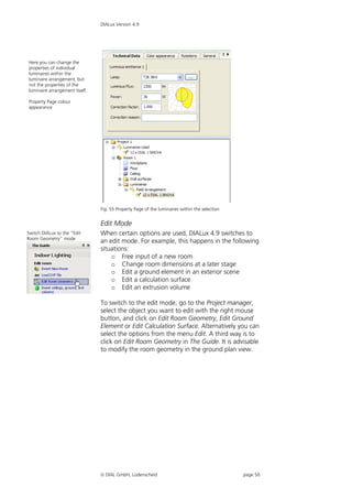
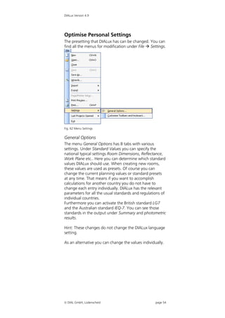
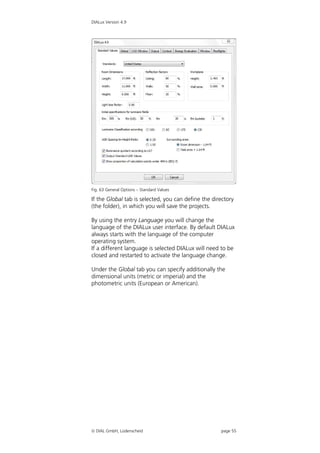
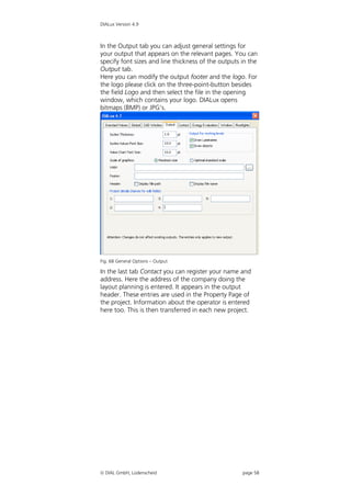
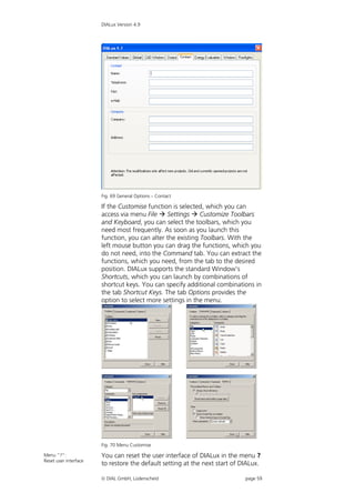
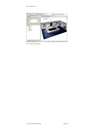
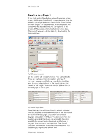
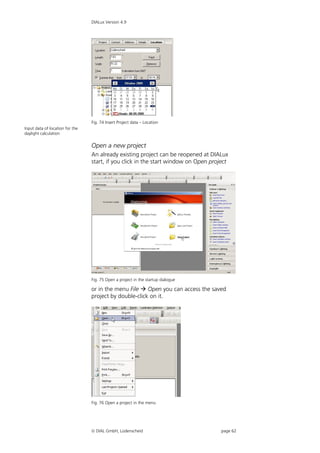
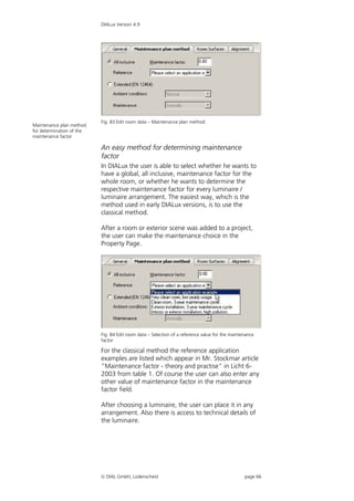
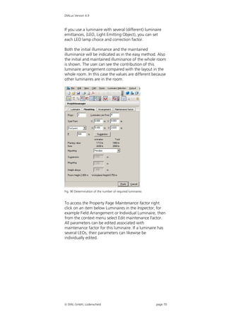
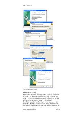
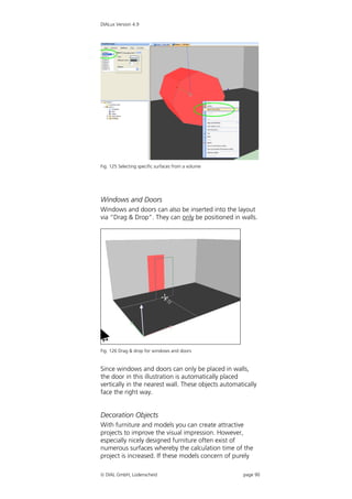
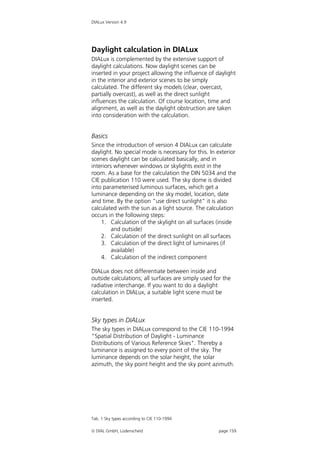
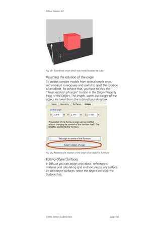
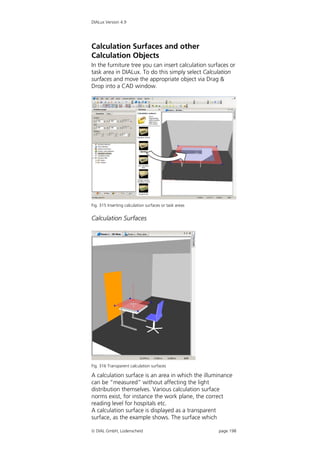
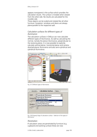
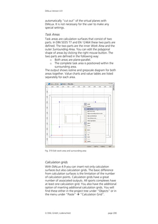
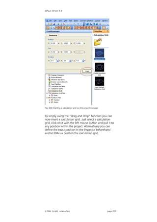
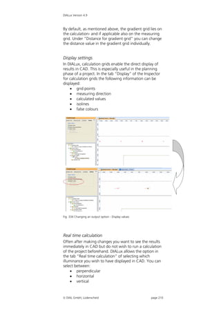
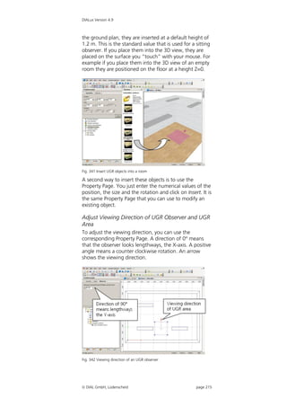
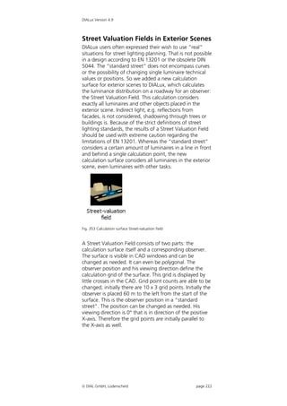
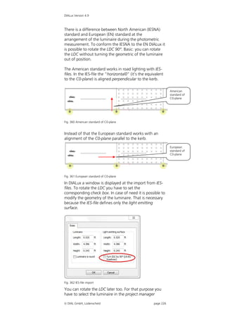
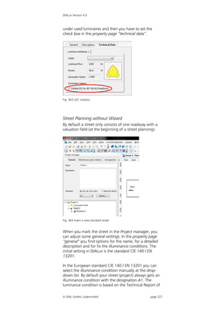
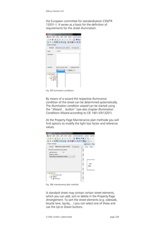
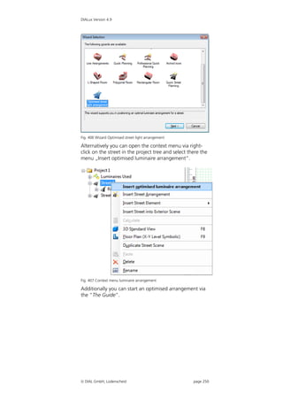
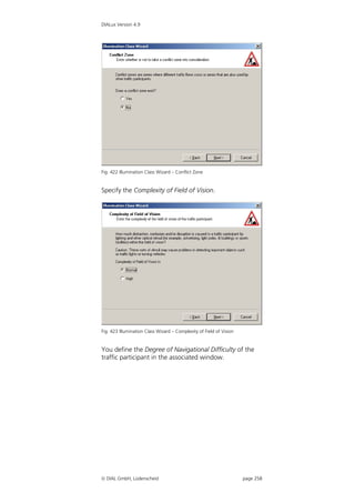
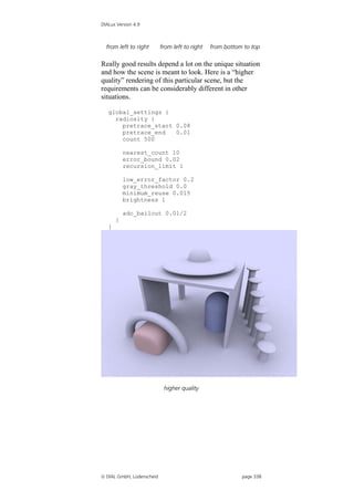
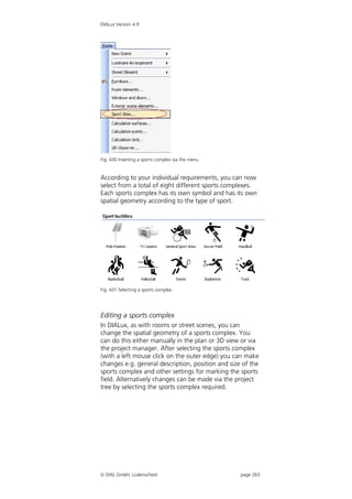
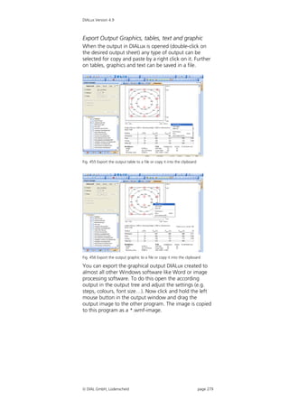
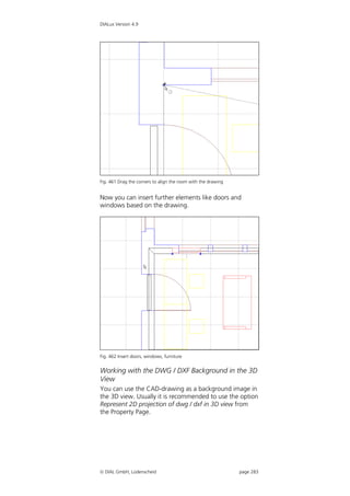
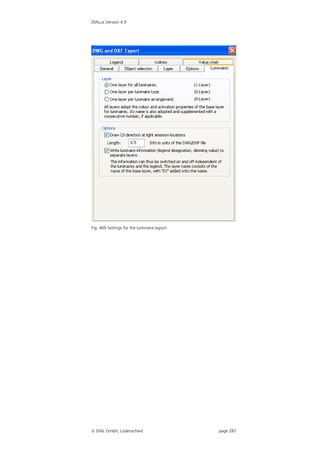
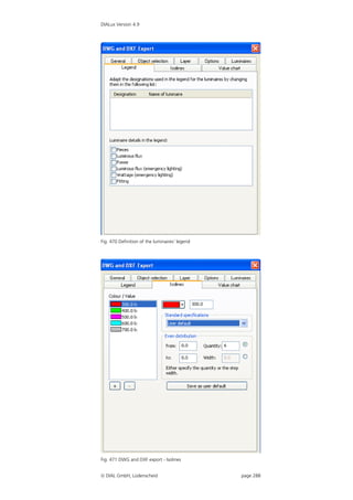
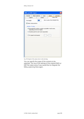
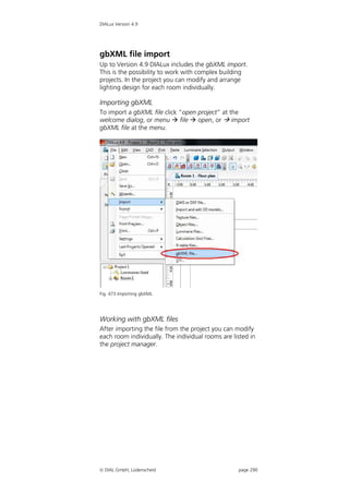
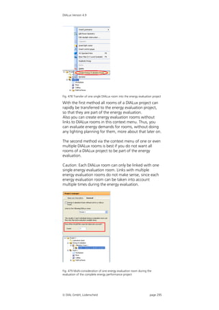
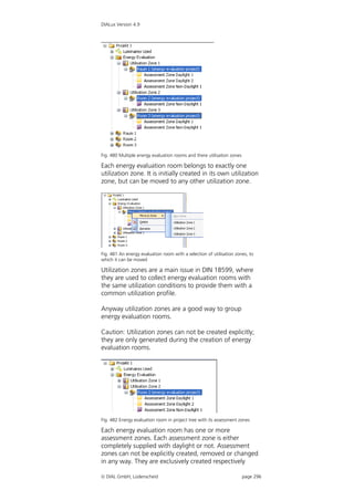
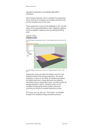
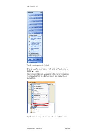
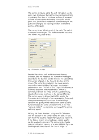
![DIALux Version 4.9
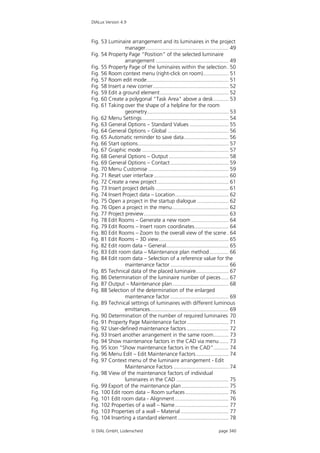
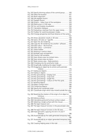
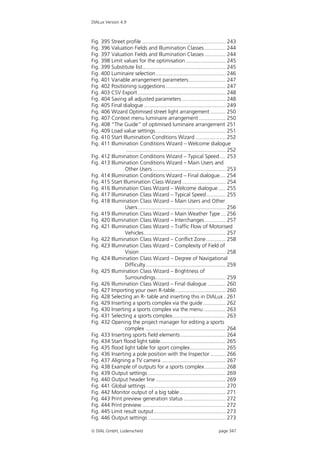
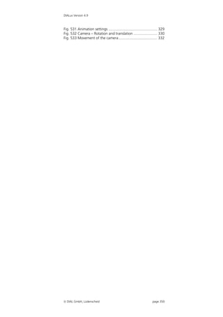
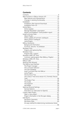
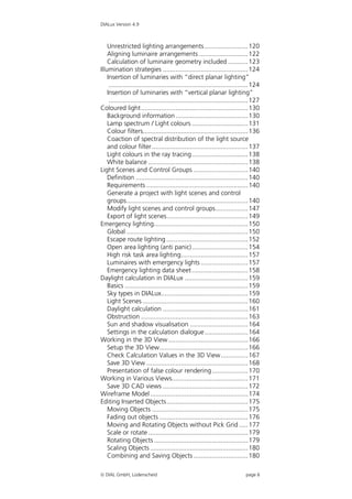
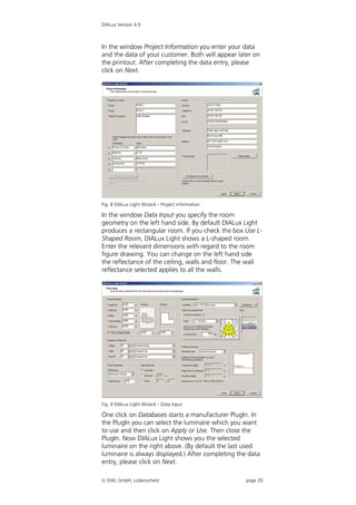
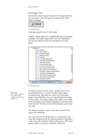
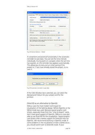
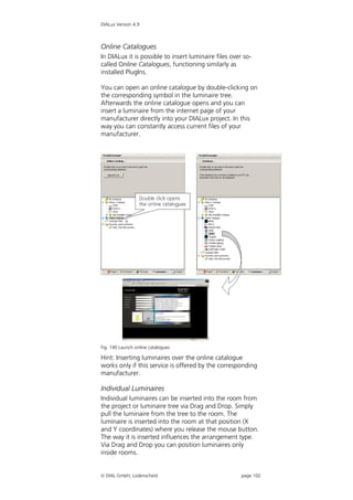
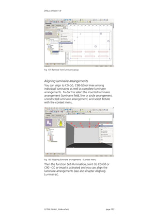
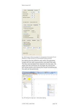
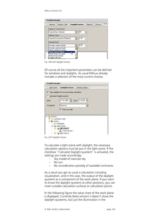
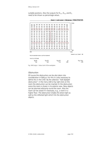
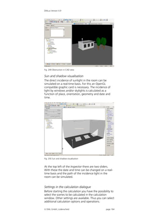
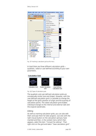
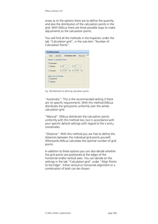
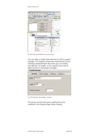
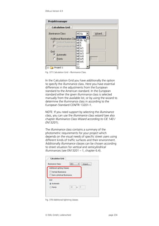
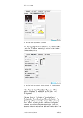
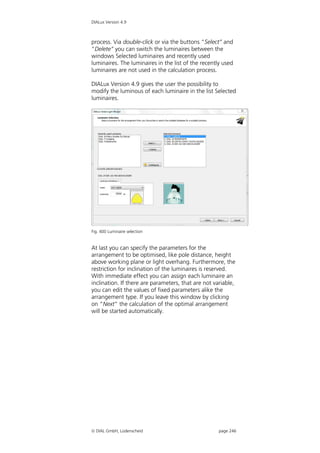
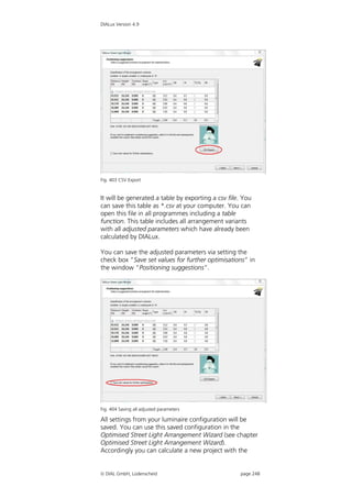
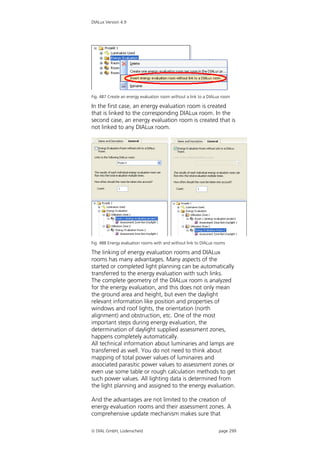
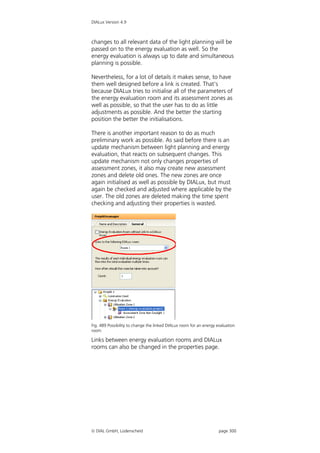
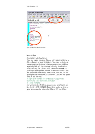
Fig. 428 Selecting an R- table and inserting this in DIALux
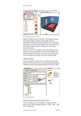
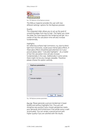
R- tables which are already available in DIALux are not
imported. DIALux compares the existing R-tables with
the new ones and provides an information report about
the (negative) result.
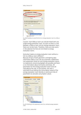
The newly inserted R-table can now be selected in the
following objects in the road surfaces:
1. Street evaluation field (Inspector of a street scene
“Calculation areas” street calculation field Street
evaluation field tab “Road surface”)
2. New/ existing street project (tab “Road surface”)
3. Assistant for quick street planning [Menu “File”
“Assistant” ”Quick street planning” page 2:
Appropriate road(s)]
If you wish to remove an inserted R-table from DIALux
then you must delete the corresponding field from the
DIALux folder. In Windows XP this is found as a default
setting under “Documents and settingsAll
usersApplication dataDIALuxRTables”. If you are using
Windows Vista you will normally find the R-tables under
“ProgrammesDIALuxRTables”.
DIAL GmbH, Lüdenscheid page 261](https://image.slidesharecdn.com/manual49en-120923214419-phpapp02/85/Manual-DIAL-lux-261-320.jpg)
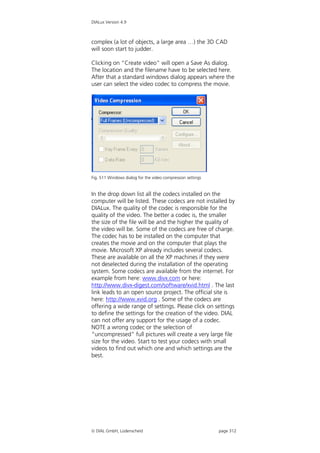
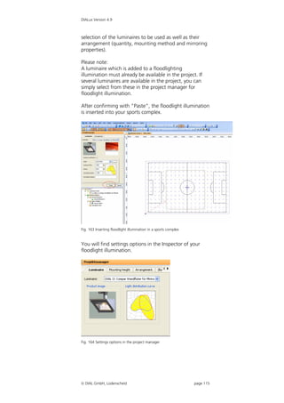
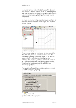
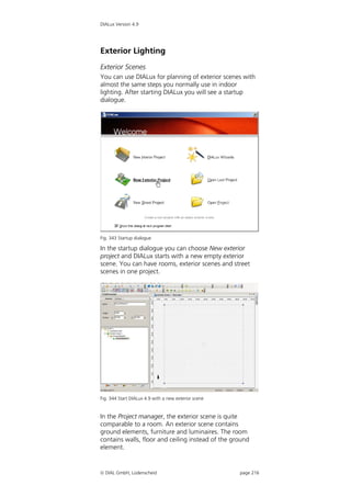
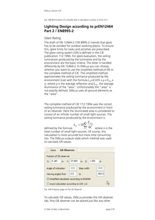
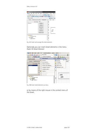
![DIALux Version 4.9
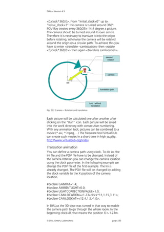
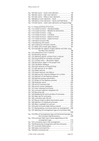
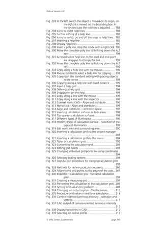
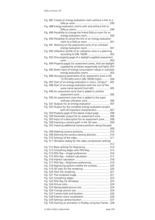
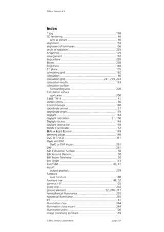
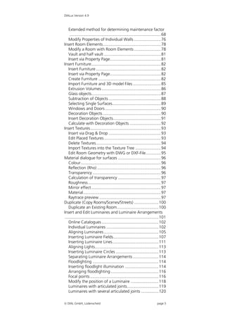
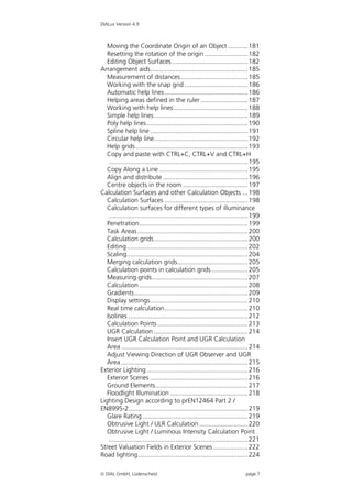
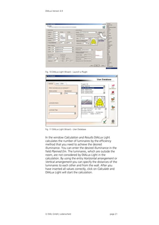
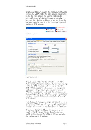
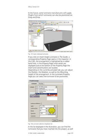
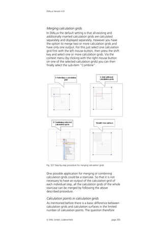
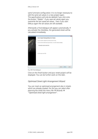
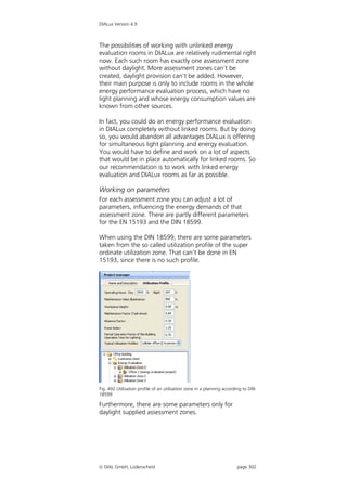
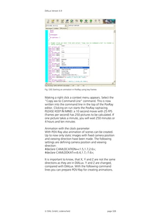
Fig. 531 Animation settings
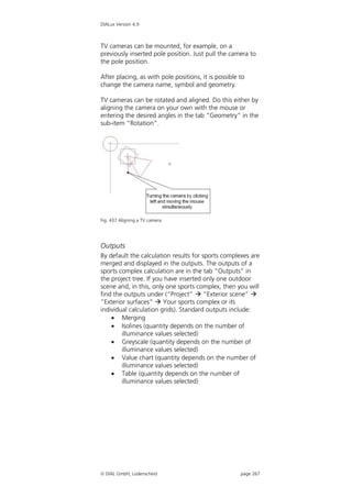
The camera will be rotated around the upwards axis.
Because of that, we will have a look around the room.
Rotate <0,clock*360,0> defines the rotation around the
up axis. Remember, Y and Z are exchanged, compared
with DIALux. Clock is a counter which is going upwards
from 0 to 1. The definition of the clock has to be done in
the Ini file of POV-Ray. To do this open the Ini file by
clicking on the icon. In this Ini file a section with the
correct resolution, anti-aliasing and step width of the
clock has to be added. Example:
[320x240, Animation] Name
Width=320 resolution width
Height=240 resolution height
Antialias=Off anti-alias switched off
Initial_Frame=1 Image to start with
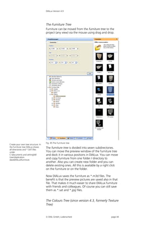
Final_Frame=25 Image to stop with,
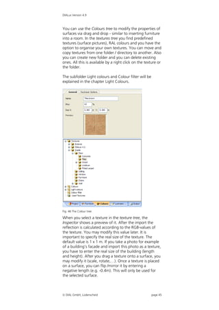
defines the number of
images
Initial_Clock=0.0 start value of clock
Final_Clock=1.0 stop value of clock
After changing the Ini file, POV-Ray has to be closed and
restarted. After the restart of POV-Ray this section can be
selected in the top left area of the editor.
Initial_Frame and Final_Frame define the number of
pictures to be rendered. In our example there are 25
pictures. Initial_Clock and Final_Clock should be taken
without changing. In Europe there are 25 frames per
second in PAL format commonly. A 10 seconds lasting
film needs 250 pictures (frames). In our example we
create 25 pictures, coded as a PAL movie, it will last 1
second. In the POV file we have added the line rotate
DIAL GmbH, Lüdenscheid page 329](https://image.slidesharecdn.com/manual49en-120923214419-phpapp02/85/Manual-DIAL-lux-329-320.jpg)