More Related Content
Similar to Extracted pages from LightTools-Basic-Training-E-learning_5.pdf (20)
More from ManhHoangVan (9)
Extracted pages from LightTools-Basic-Training-E-learning_5.pdf
- 1. 201
© 2021 Synopsys, Inc.
Dispersion
Chromatic
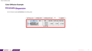
6) In the Surface tab, specify only RearSurface as the emitting surface.
Color Diffusion Example
Machine Translated by Google
- 2. 2) Right click on the virtual face and add face receiver
1) Create a 20 x 20 virtual face at (0,0,30)
Chromatic Dispersion
202
© 2021 Synopsys, Inc.
4. Create a face receiver
Color Diffusion Example
Machine Translated by Google
- 3. 203
© 2021 Synopsys, Inc.
Chromatic Dispersion
5. Click the simulation start icon ( )
Color Diffusion Example
Machine Translated by Google
- 4. © 2021 Synopsys, Inc. 204
2) Edit all sub-elements > Optical Properties > Select Transmitting
1) Right-click the prism object in the system explorer
Dispersion
Chromatic
7. Change rendering mode to trans (translucent)
6. Change the optical properties to transmit the entire surface of the prism.
Color Diffusion Example
Machine Translated by Google
- 5. © 2021 Synopsys, Inc. 205
1) Right-click the prism object in the system explorer
3) In the Optical Smoothing tab, change the ray tracing mode to ray splitting.
2) Select Edit all subelements > Optical properties > Create and specify new optical properties.
Chromatic Dispersion
8. Change optical properties by splitting rays across the entire surface of the prism.
Color Diffusion Example
Machine Translated by Google
- 6. © 2021 Synopsys, Inc. 206
Chromatic Dispersion
9. Click to rerun simulation
Color Diffusion Example
Machine Translated by Google
- 7. © 2021 Synopsys, Inc. 207
2) Click to rerun simulation
1) In the Coordinates tab of the Light Source Properties window , enter an alpha angle of 15 degrees.
Chromatic Dispersion
10. Run the simulation after changing the angle of incidence to avoid total reflection.
Color Diffusion Example
Machine Translated by Google
- 8. © 2021 Synopsys, Inc. 208
2) Edit all sub-elements > Optical Properties > Select Transmitting
1) Right-click Prism in the system explorer
Chromatic Dispersion
11. Change optical properties to transmit all sides of the prism again.
12. Rerun simulation
Color Diffusion Example
Machine Translated by Google
- 9. 209
© 2021 Synopsys, Inc.
2) From the menu, Analyze > Illuminance Display > Color Chart Viewer
1) From the menu, View > Simulation Results > True Color
Dispersion
Chromatic
13. To check color dispersion
Color Diffusion Example
Machine Translated by Google
- 10. © 2021 Synopsys, Inc. 210
1) Change mesh dimensions to 201x201 in receiver
2) In the simulation input menu, change the number of rays to 100,000 and click start forward simulation.
Chromatic Dispersion
14. To confirm accurate results
Color Diffusion Example
Machine Translated by Google
- 12. Color Diffusion Example
15. Change materials to increase color dispersion
© 2021 Synopsys, Inc. 212
Chromatic Dispersion
2) Select TIF6 material with relatively small Abbe number from the glass map and apply it
1) In the prism properties window, go to the Material tab and click Glass Map.
Machine Translated by Google
- 15. flashlight example
2. Enter 12mm distance from focus to reflector vertex.
3. Enter -1 to define the depth of the reflector
1. Create a reflector using the SpunParabola_M icon
© 2021 Synopsys, Inc. 215
FlashLight
4. Enter 60mm depth of reflector
Machine Translated by Google
- 16. flashlight example
5. Right-click refl in System Explorer and open the Properties window.
7. Select LensRearSurface and enter parameters to be the same as FrontSurface.
© 2021 Synopsys, Inc. 216
FlashLight
6. Expand the Object Explorer and select LensFrontSurface to check the parameters.
Machine Translated by Google
- 18. © 2021 Synopsys, Inc. 218
10. Click the NSFanAim icon to create NSRay
FlashLight
11. Enter the starting location of NSRay in the command line
9. Move and zoom out the view so that there is approximately 300 mm of space to the right of the reflector.
13. Enter NSRay's orientation position on the command line
12. Enter height position of NSRay in command line
Flashlight example
Machine Translated by Google
- 19. 219
© 2021 Synopsys, Inc.
15. Delete NSRay
FlashLight
14. Since it is a parabolic reflector , check that the ray is focused (0,0,0)
flashlight example
Machine Translated by Google
- 20. © 2021 Synopsys, Inc. 220
– Coordinates of virtual plane = 0,0,300
– Width = 150mm
– Height = 150mm
FlashLight
16. Create a point light source at the focus position (0,0,0) of the reflector
17. Create a virtual plane using the DummyPlane icon
16. Make sure the clip ray at the ray boundary is selected
flashlight example
Machine Translated by Google
- 21. © 2021 Synopsys, Inc. 221
– Number of trace rays = 100
– Check ray preview
– Click to start forward simulation
FlashLight
19. Select the virtual face and right-click to add face listener.
20. From the LightTools top menu, go to Ray Tracing > Simulation Input.
flashlight example
Machine Translated by Google
- 22. © 2021 Synopsys, Inc. 222
– Number of rays to trace changed to 10,000
– Click to start forward simulation
– Ray Tracing > Simulation Input
FlashLight
21. To analyze by increasing the number of rays
flashlight example
Machine Translated by Google
- 23. © 2021 Synopsys, Inc. 223
FlashLight
22. From the top menu, Analyze > Illuminance Display > Scattering Chart
flashlight example
Machine Translated by Google
- 24. © 2021 Synopsys, Inc. 224
FlashLight
23. Receiver’s Illuminance Mesh properties window to analyze results
flashlight example
Machine Translated by Google
- 25. © 2021 Synopsys, Inc. 225
– Click Isometric View on the toolbar
– Analysis > Illuminance display > Lumviewer
– Click on the slice diagram icon
FlashLight
24. Check the illuminance distribution using the LumViewer function
25. Rotate the chart to an isometric view and check the slice diagram.
flashlight example
Machine Translated by Google
- 26. © 2021 Synopsys, Inc. 226
– Import KPR 103.1.ent file
– Delete point light source
– File > Load library component from the top menu
FlashLight
26. Change light source
flashlight example
Machine Translated by Google
- 27. © 2021 Synopsys, Inc. 227
– Create a mechanical cylinder with a radius of 5mm and a length of 50mm at the (0,0,-30) position.
– After selecting the reflector, click Subtract with the mechanical cylinder selected.
FlashLight
27. Turn off ray preview (
28. Drill a hole in the reflector since it takes up the same space as part of the reflector.
29. Type trans in the command line to switch to translucent mode and check for holes
) and then check the lamp model.
flashlight example
Machine Translated by Google
- 28. © 2021 Synopsys, Inc. 228
– Number of rays changed to 20,000
– From the menu, Analyze > Illuminance Display > LumViewer
– From the menu Ray Tracing > Enter Simulation
– Click to start forward simulation
FlashLight
30. Re-run the simulation with more realistic lighting and check the chart.
flashlight example
Machine Translated by Google
- 29. © 2021 Synopsys, Inc. 229
– Turn off ray preview
– In the Utility window, Geometry > Surface Reflector
– Delete reflector
– From the menu Tools > Utility Library
FlashLight
31. Use the Surface Reflector Utility to Improve Uniformity
flashlight example
Machine Translated by Google
- 30. © 2021 Synopsys, Inc. 230
– Go to the Light Source/Receiver tab in the Utilities window
– Uncheck all
FlashLight
32. Since the model already has a light source and a receiver, turn off the automatic creation of light sources and receivers.
flashlight example
Machine Translated by Google
- 31. – Click Create Cross Section
– Hole radius = 5.6
– Target Distance = 300
– Target half size = 50
– edge radius = 53
– edge angle = 60 (default)
FlashLight
231
© 2021 Synopsys, Inc.
33. In the Utilities window, go to the Reflector Data tab
flashlight example
Machine Translated by Google
- 32. 232
© 2021 Synopsys, Inc.
– From the menu Ray Tracing > Enter Simulation
– Check ray preview
– Change preview ray count to 200
– Number of rays to trace changed to 100,000
– Click to start forward simulation
FlashLight
34. After checking the generated reflector shape, change the rendering mode to wireframe.
35. Rerun simulation to compare results
flashlight example
Machine Translated by Google
- 33. 233
© 2021 Synopsys, Inc.
– From the menu, Analyze > Illuminance Display > LumViewer
FlashLight
36. Check the results
flashlight example
Machine Translated by Google
- 34. 234
© 2021 Synopsys, Inc.
– Create a ‘mechanical cylinder 1’ with a radius of 66mm and a length of 68mm at the (0,0,-30) location.
– After selecting ‘Mechanical Cylinder 1’, click Subtract with ‘Mechanical Cylinder 2’ selected.
– Change rendering mode to trans mode to check current model
– Turn off ray preview
– Create ‘Mechanical Cylinder 2’ with a radius of 62mm and a length of 80mm at the (0,0,-40) location.
FlashLight
37. To make the flashlight body
flashlight example
Machine Translated by Google
- 35. © 2021 Synopsys, Inc. 235
– Create a cylinder by clicking three points
– Adjust coordinates and shape as shown below in the properties window
– Click on the mechanical cylinder icon
– Set radius 66mm, length 66mm, taper 0.5
FlashLight
38. Create a tapered cylinder connected to the body
flashlight example
Machine Translated by Google
- 36. © 2021 Synopsys, Inc. 236
– Right-click in the 3D design view margin and click Snap > Object.
– Click at a location with a radius of 33mm and a length of 300mm.
– Adjust coordinates and shape as shown below in the properties window
– Click on the mechanical cylinder icon
– Click on the left side of the ‘previously created cylinder’
FlashLight
39. Creating the handle part of the flashlight
flashlight example
Machine Translated by Google
- 37. 237
© 2021 Synopsys, Inc.
FlashLight
40. Check out all flashlight models
flashlight example
Machine Translated by Google