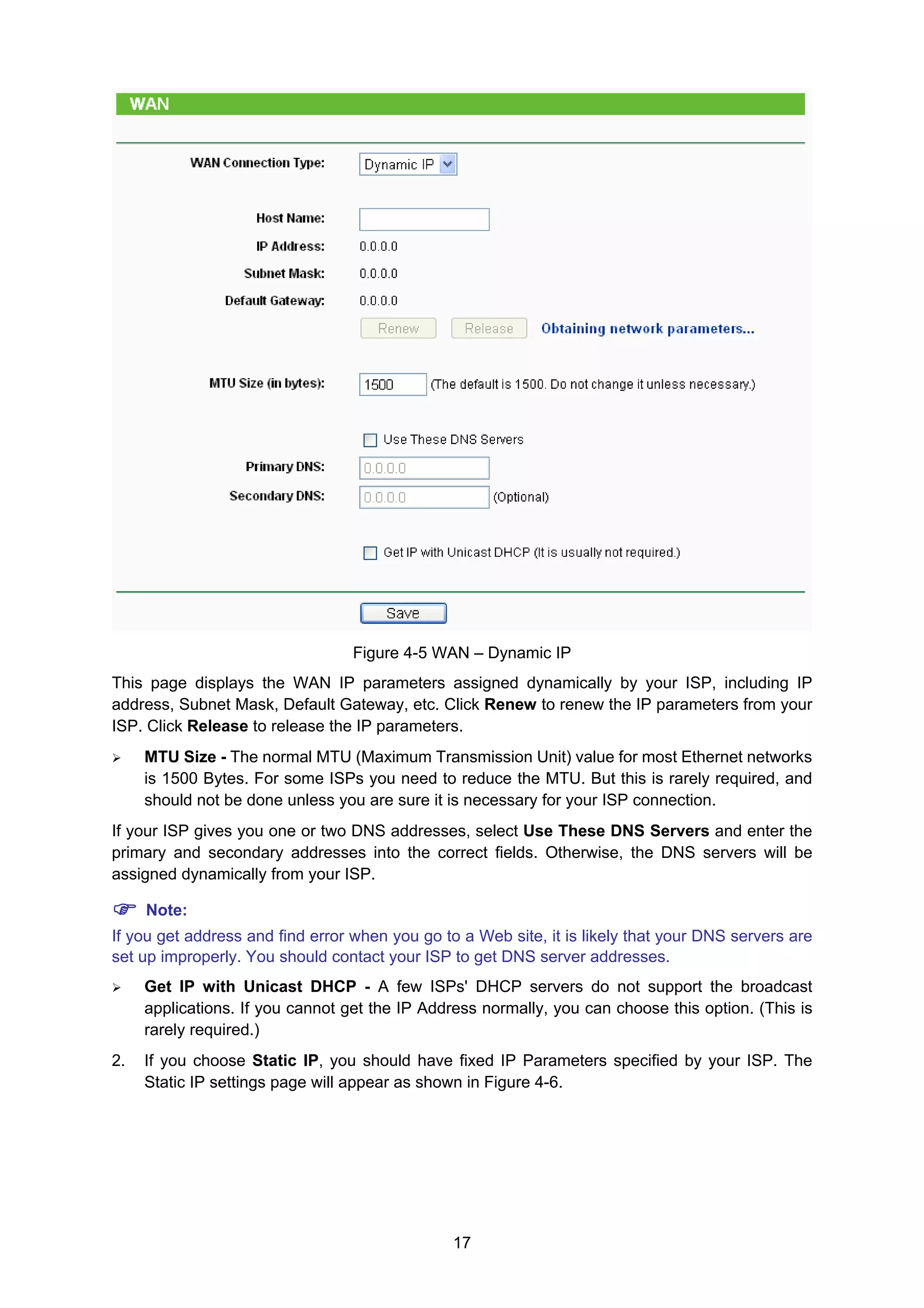
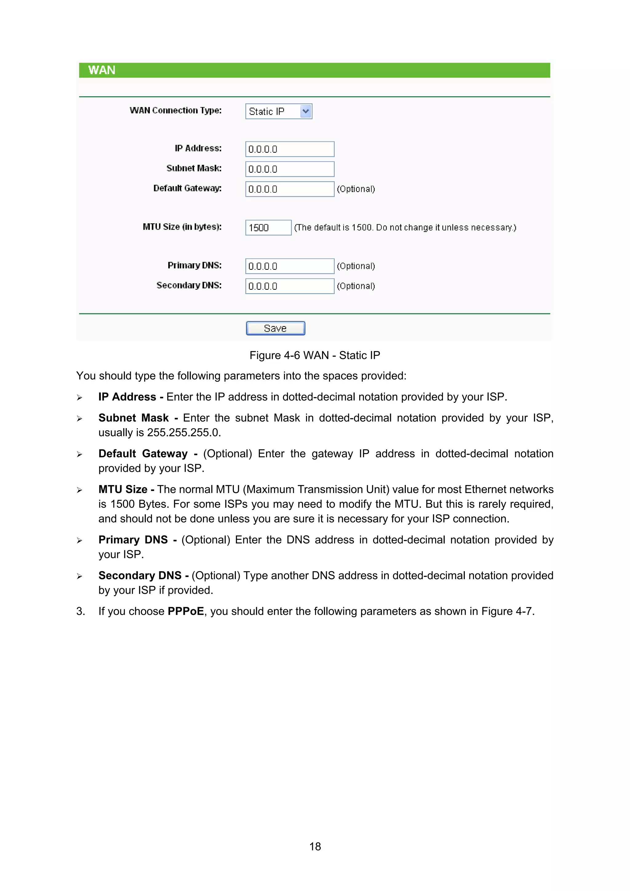
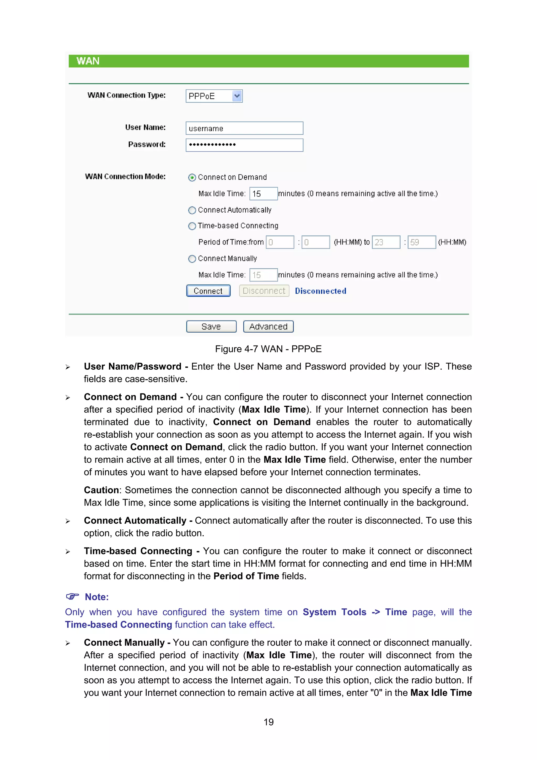
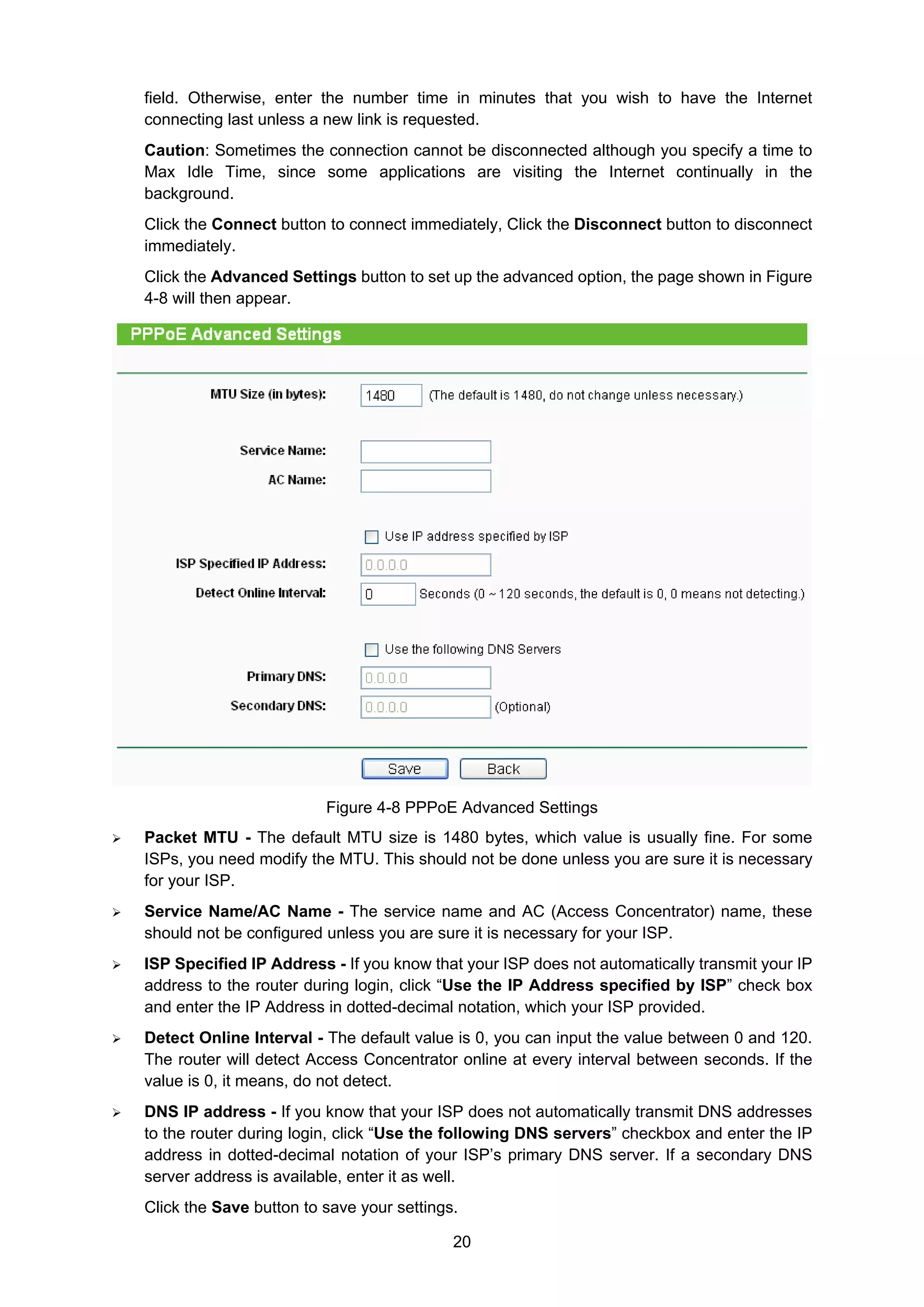
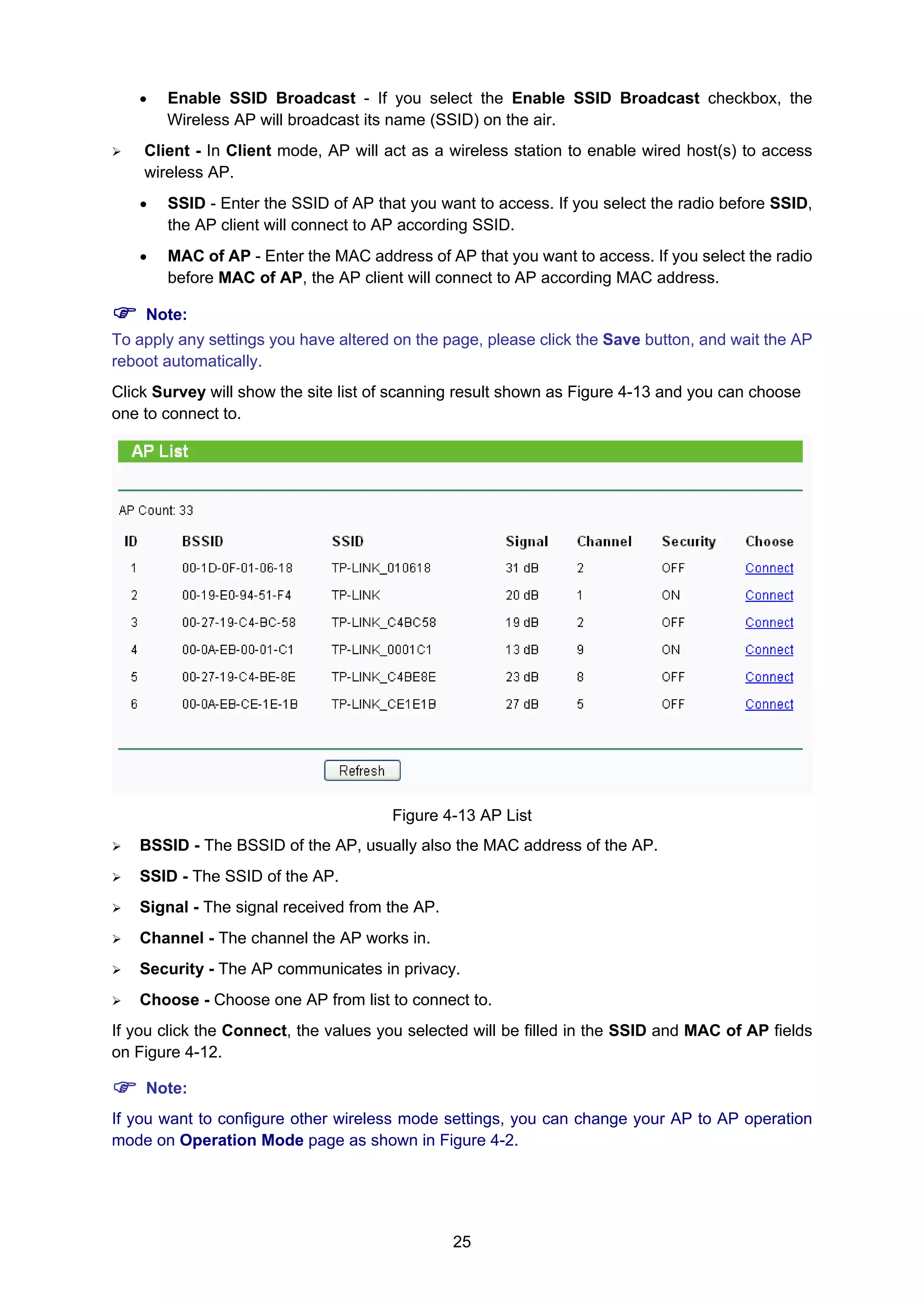
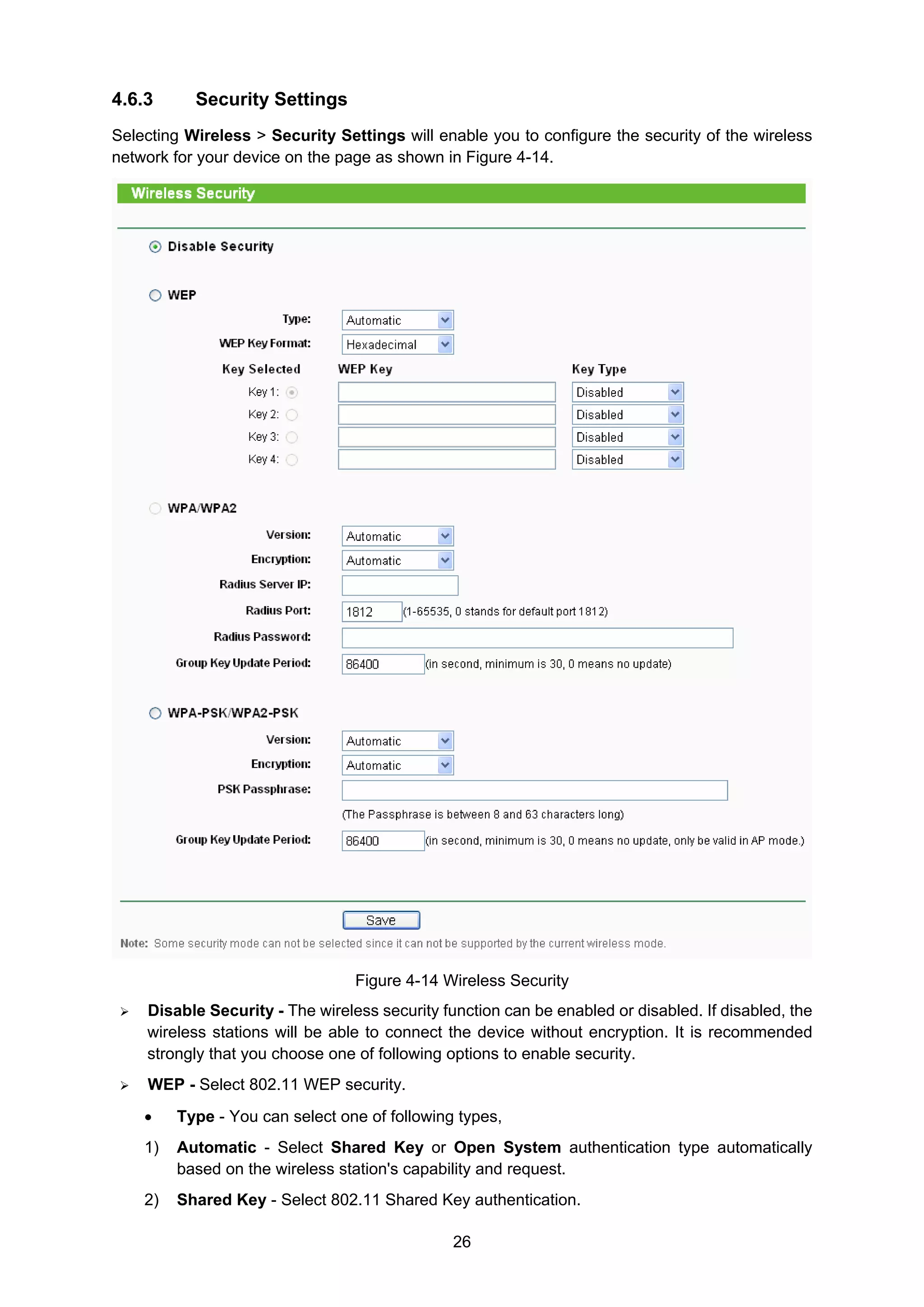
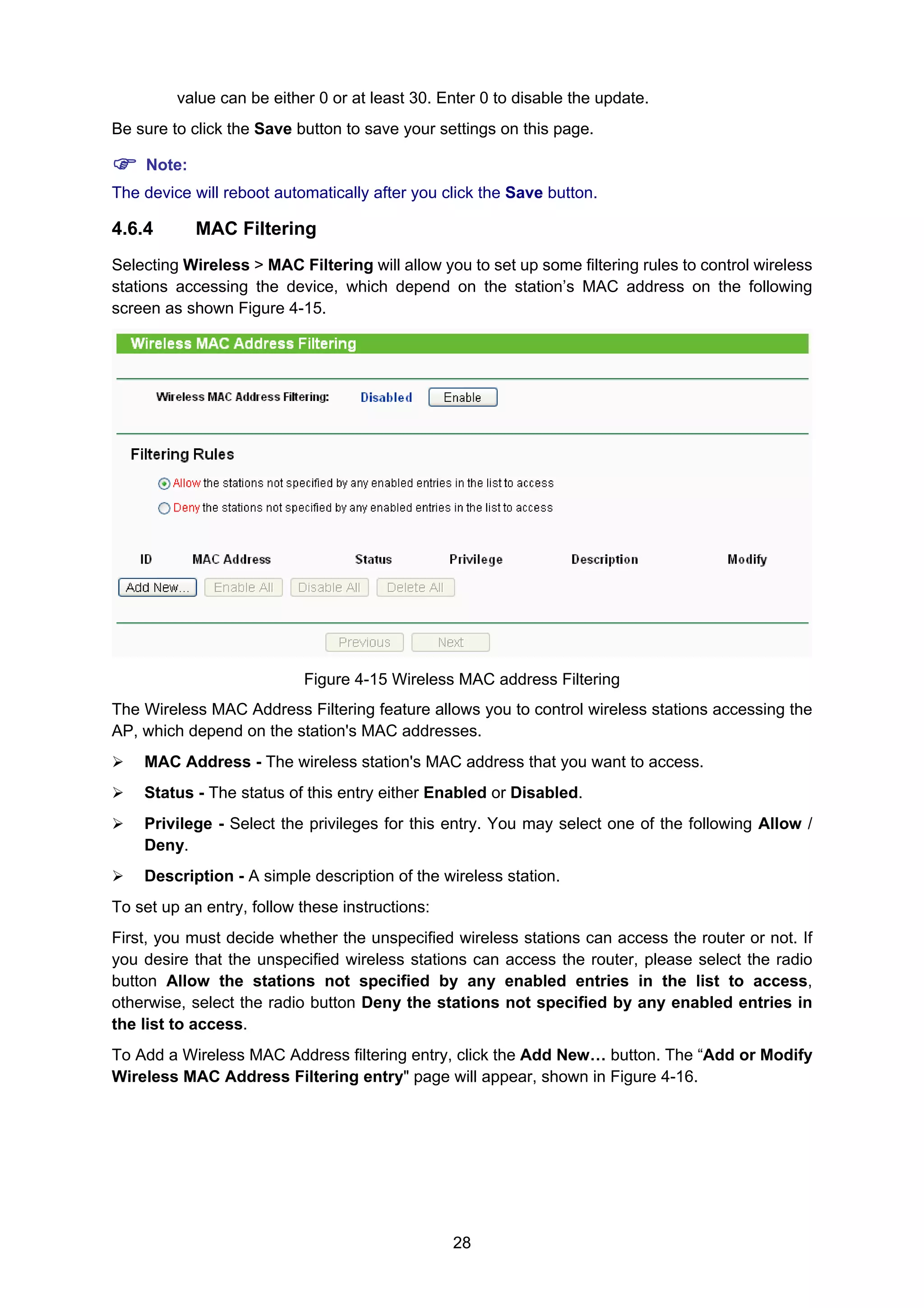
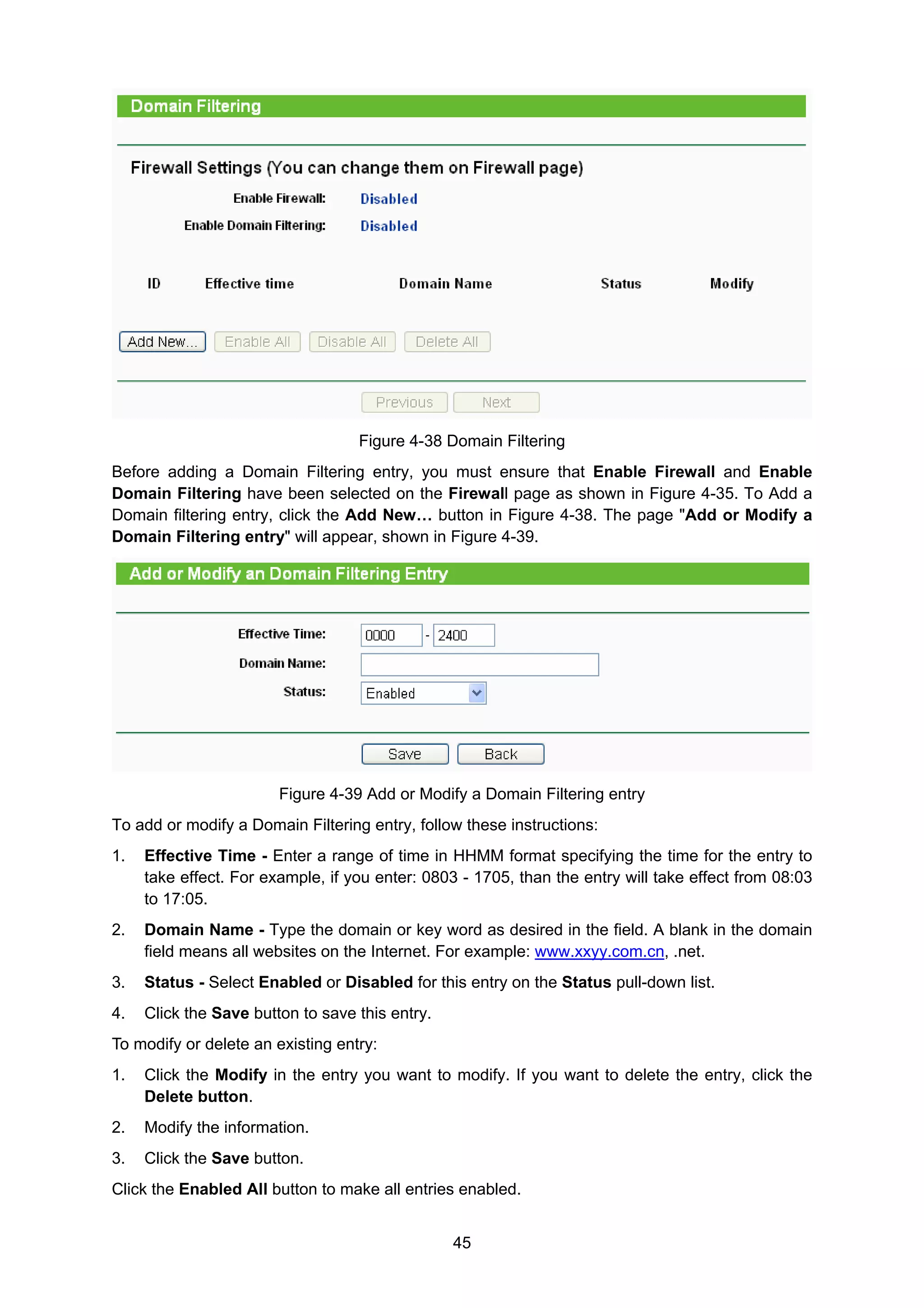
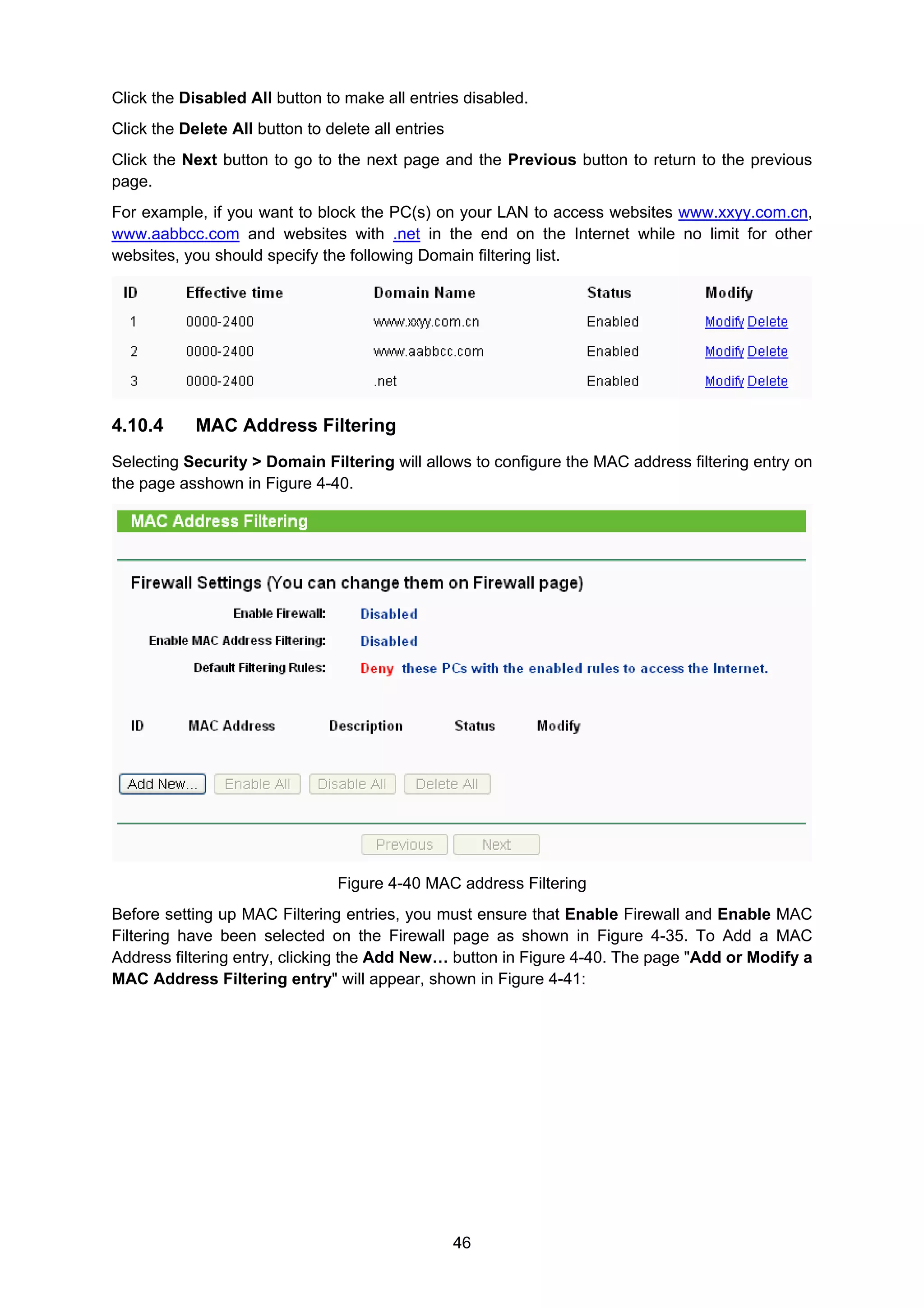
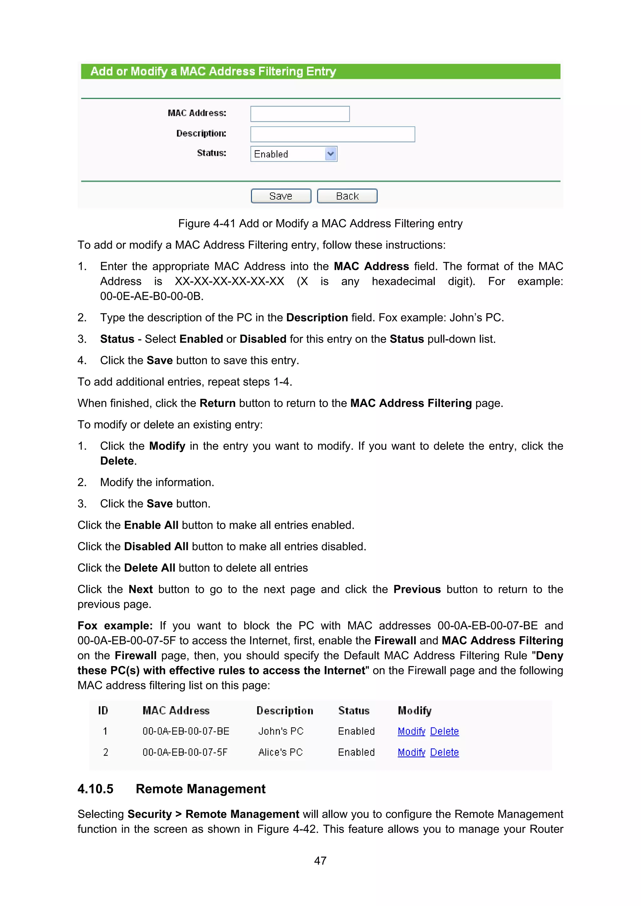
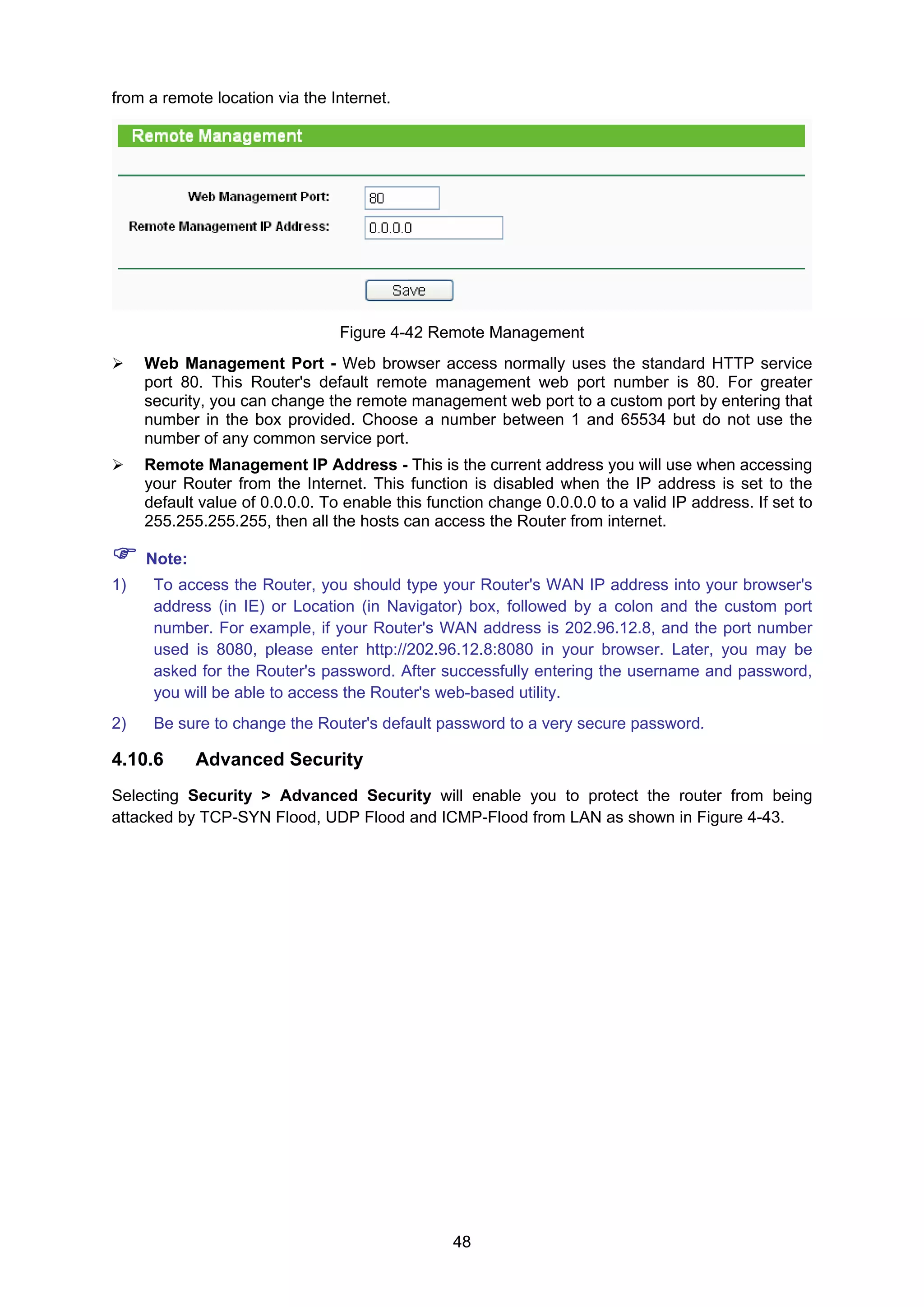
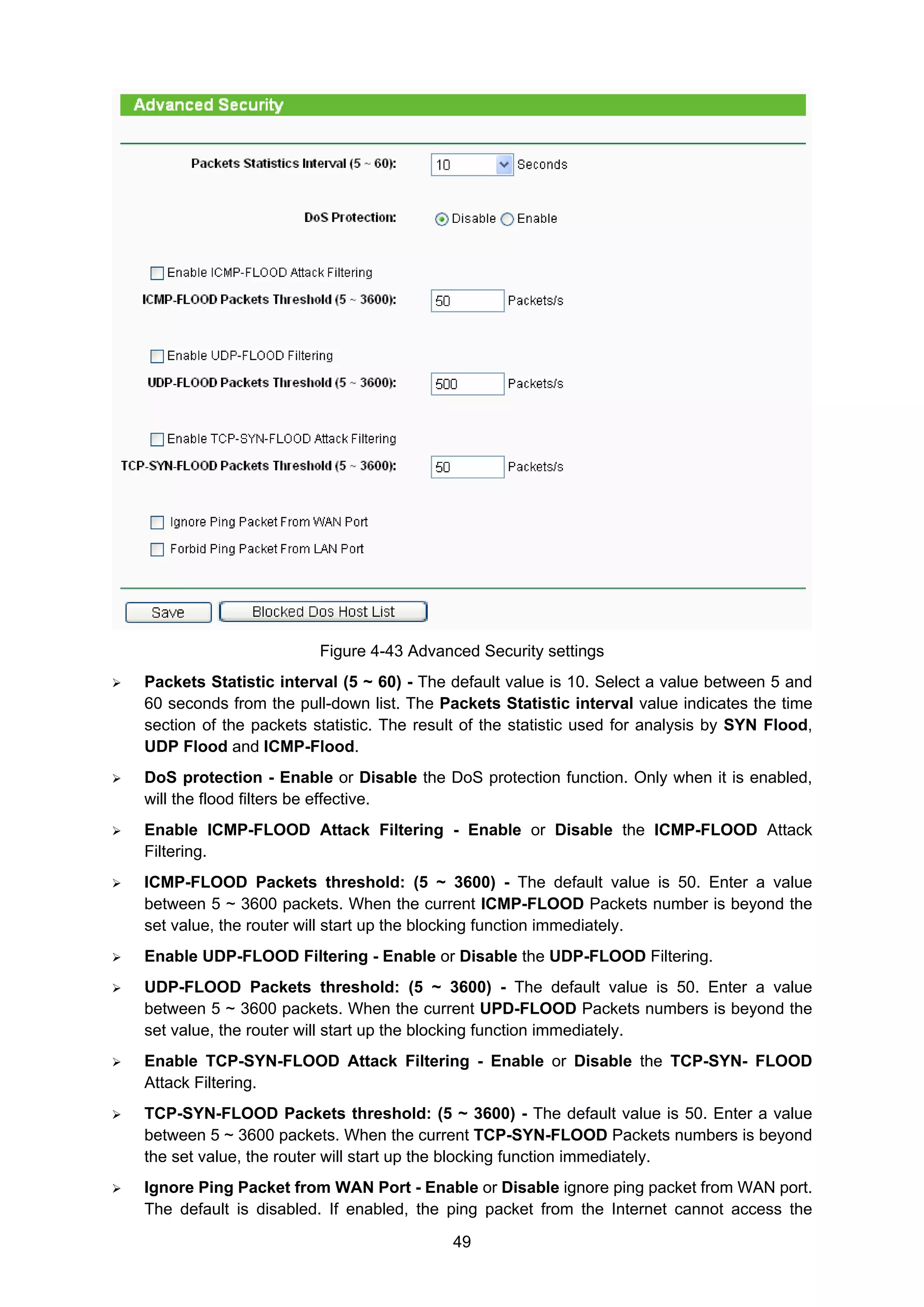
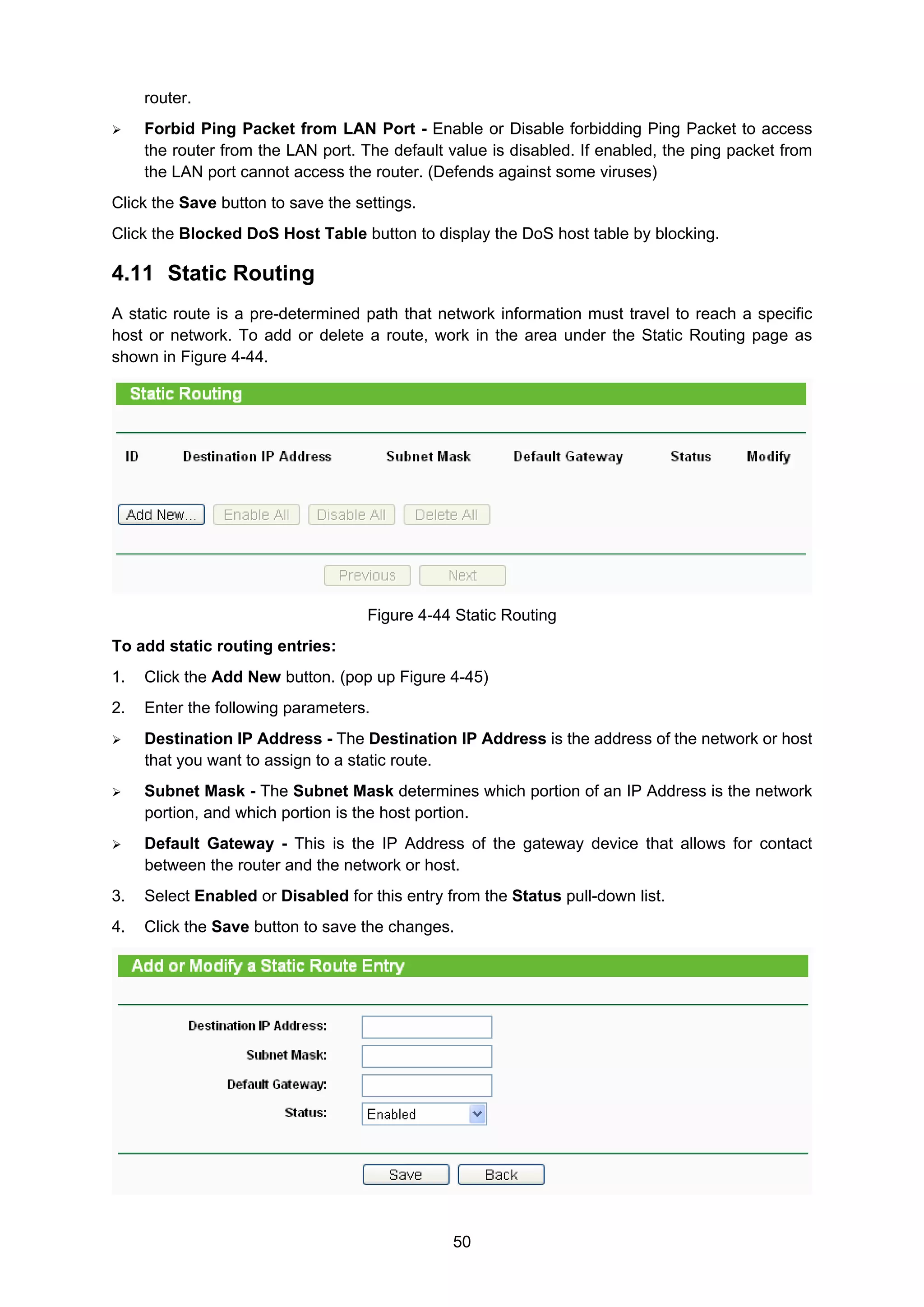
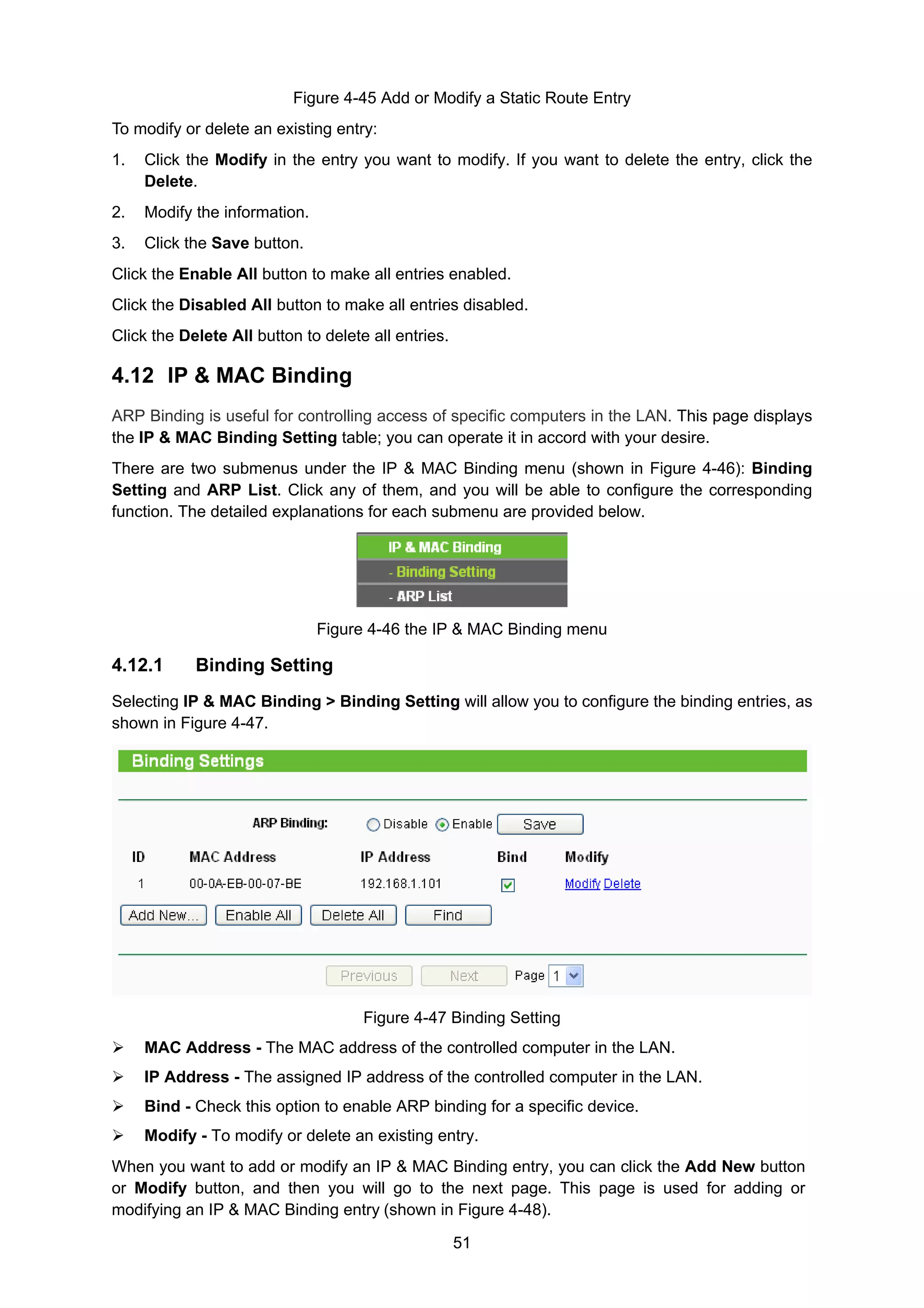
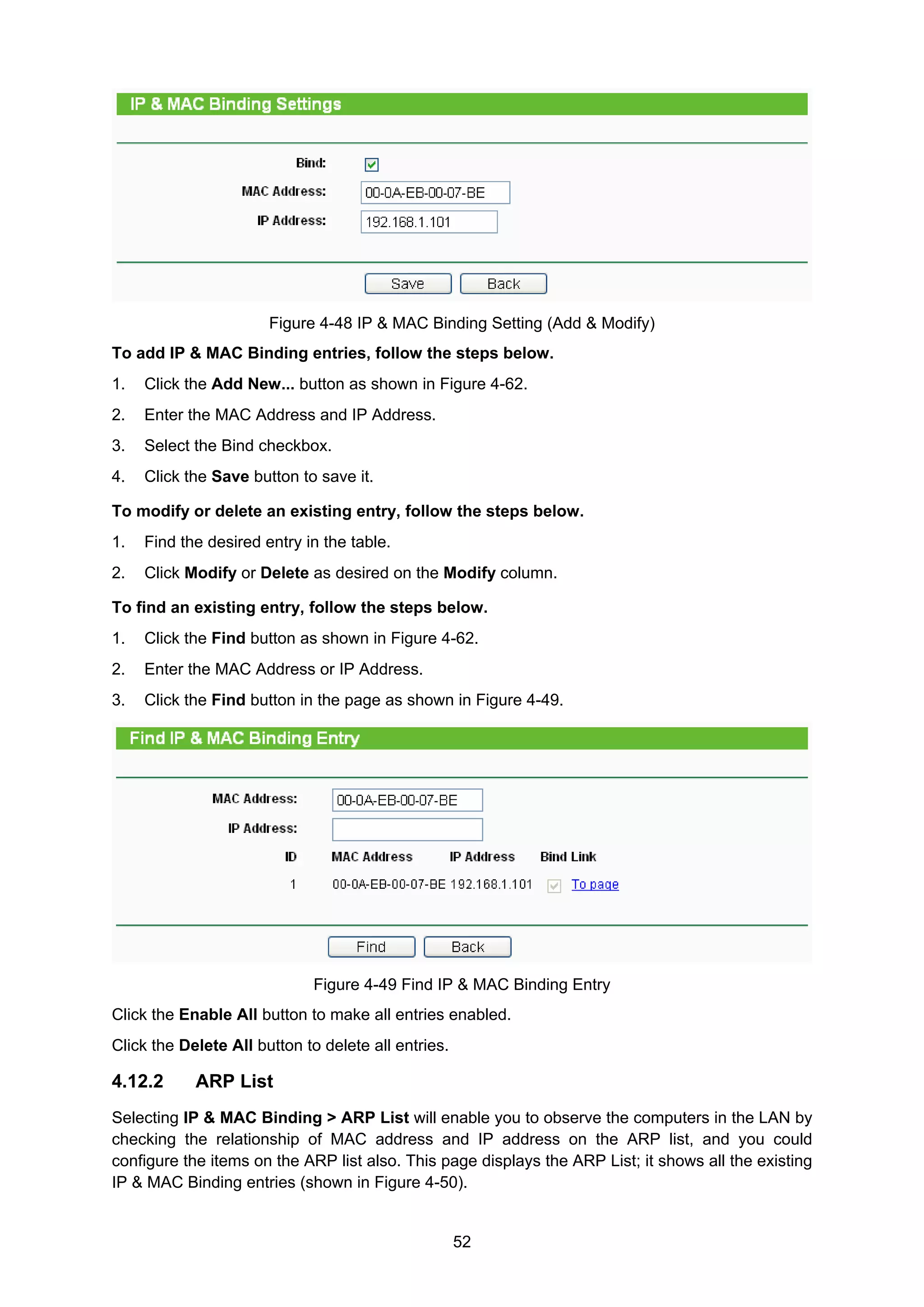
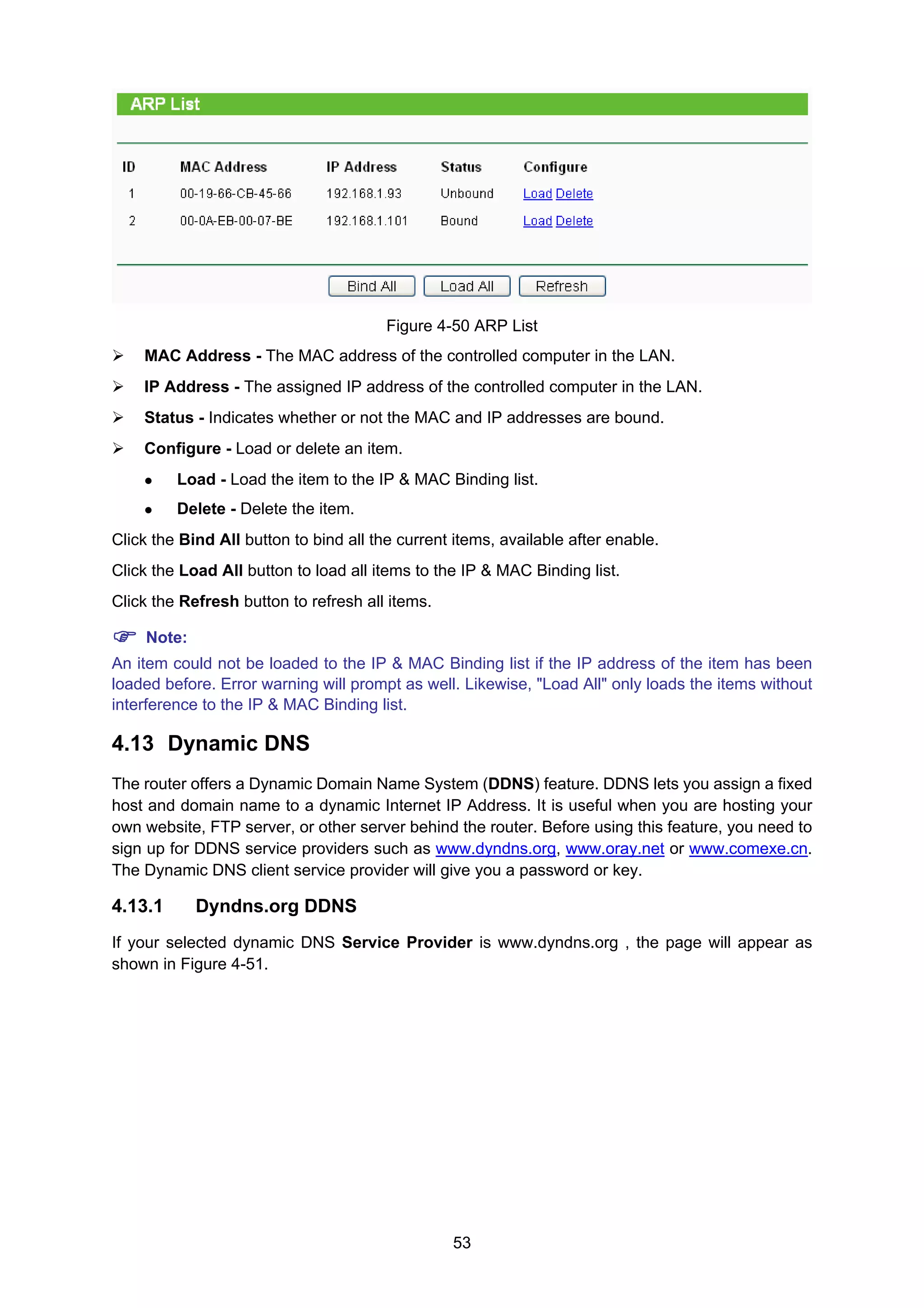
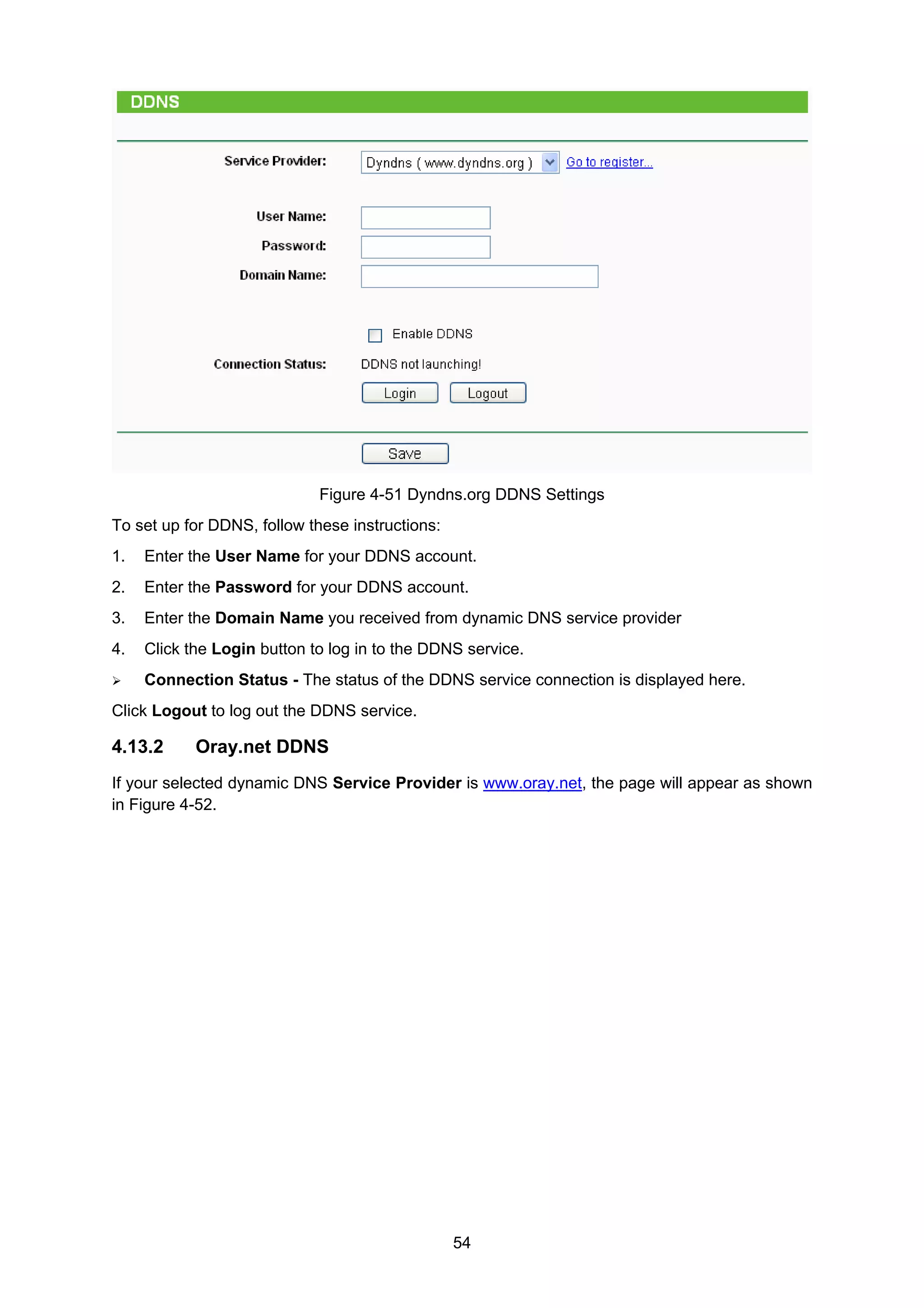
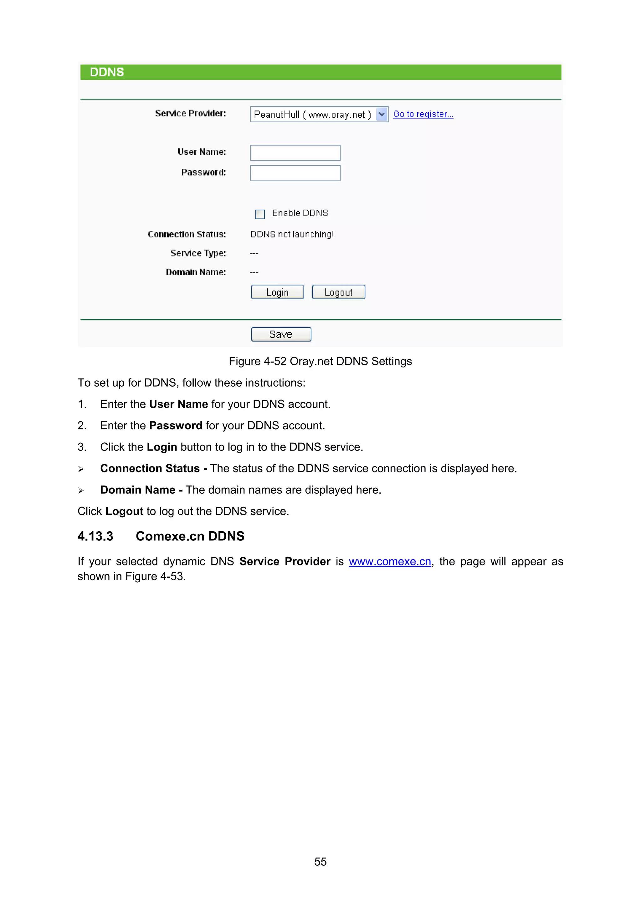
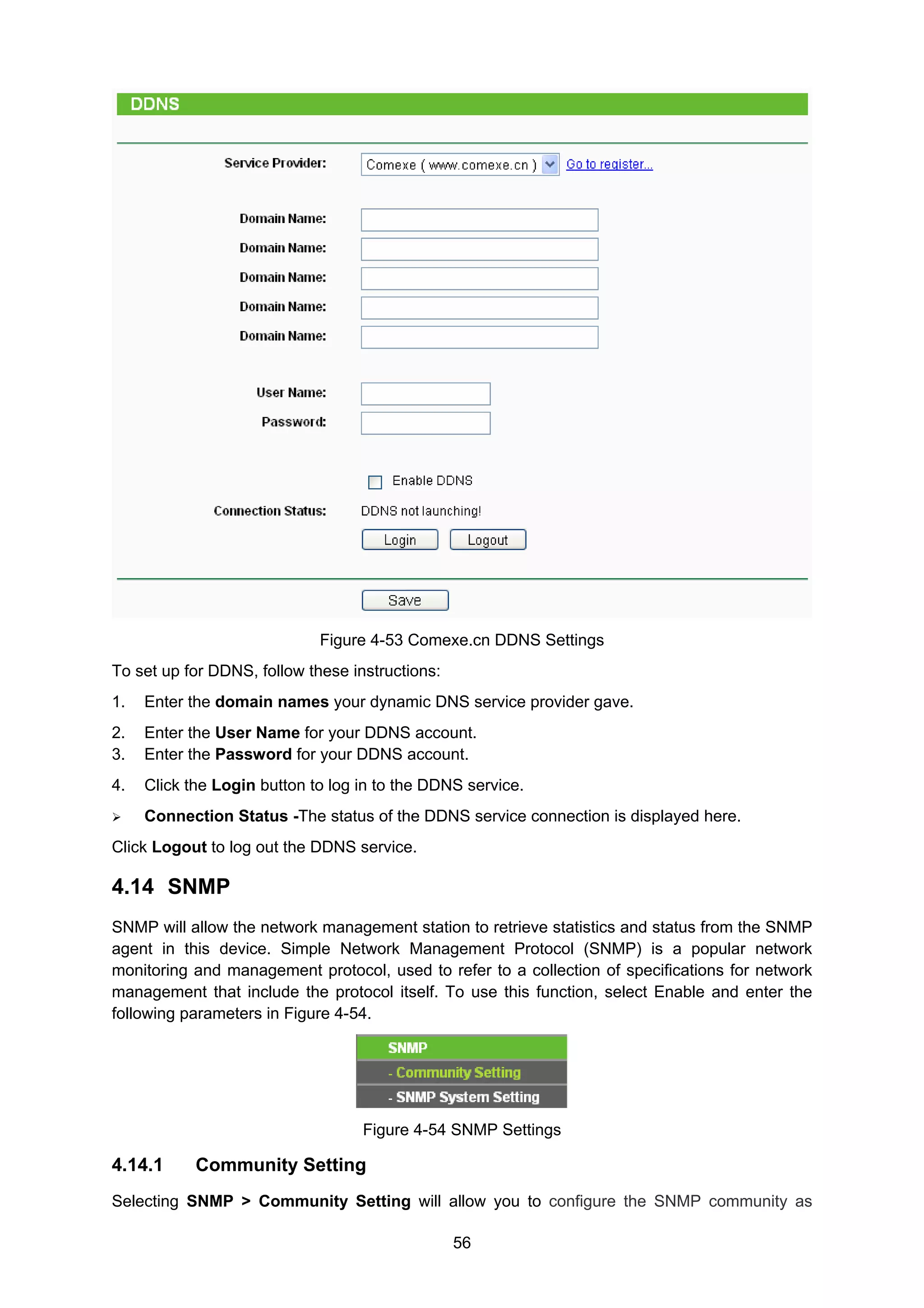
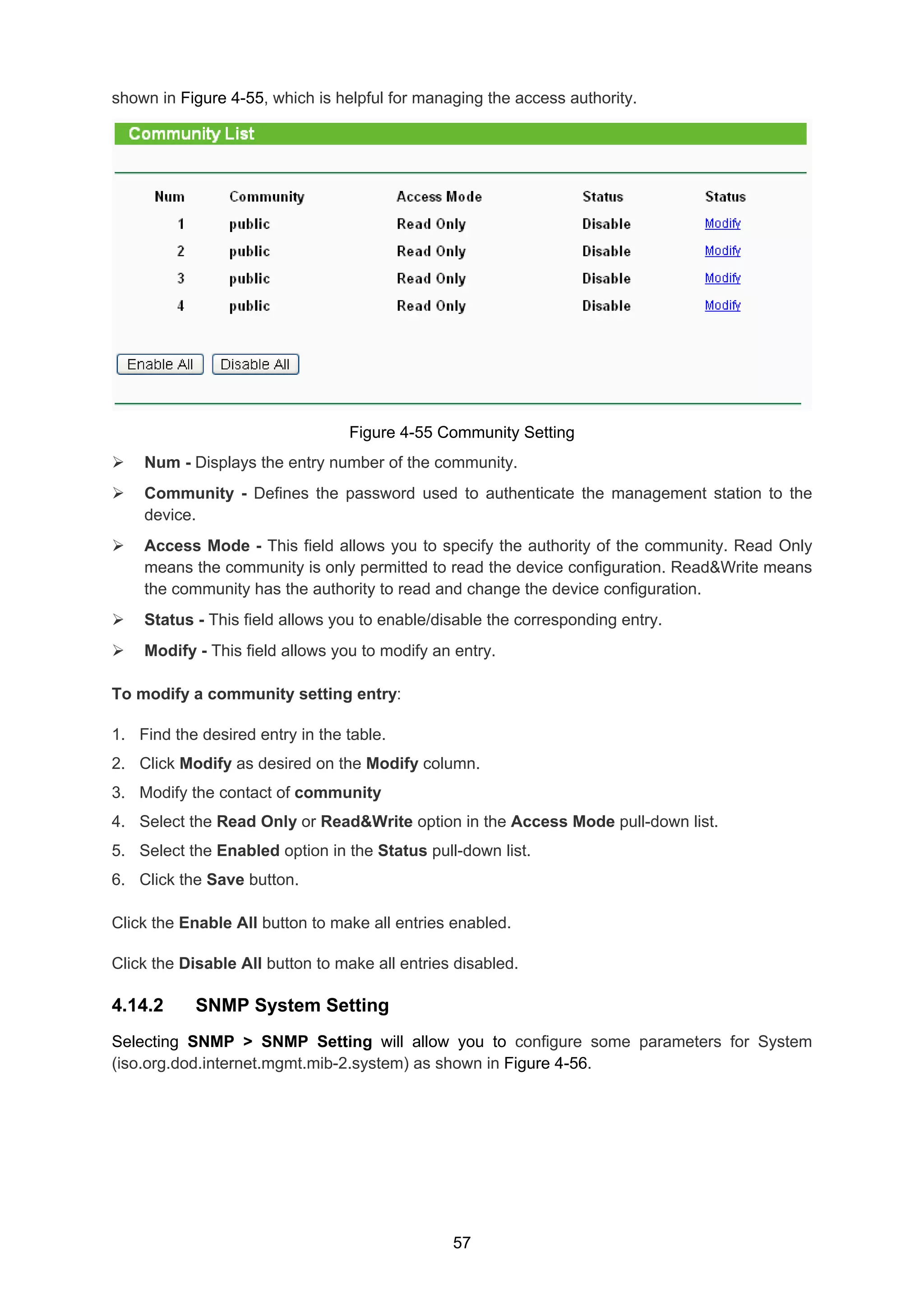
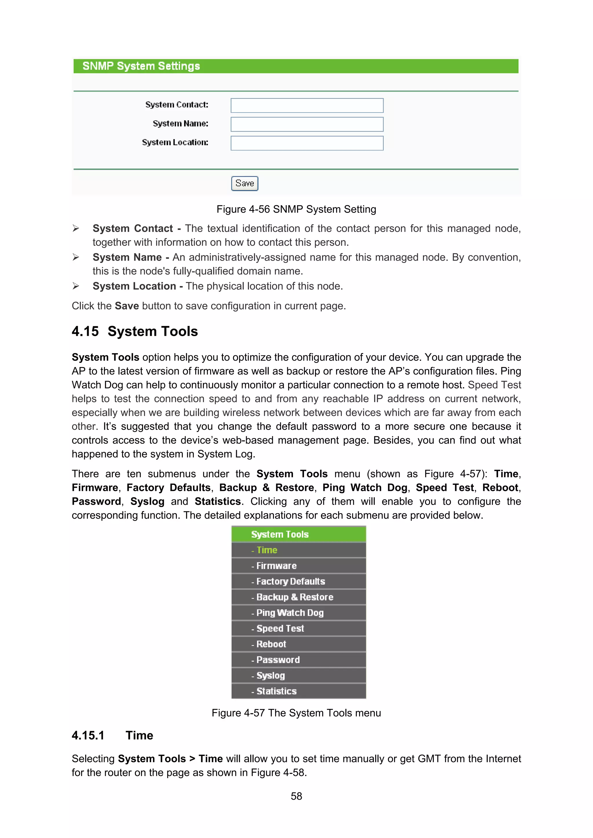
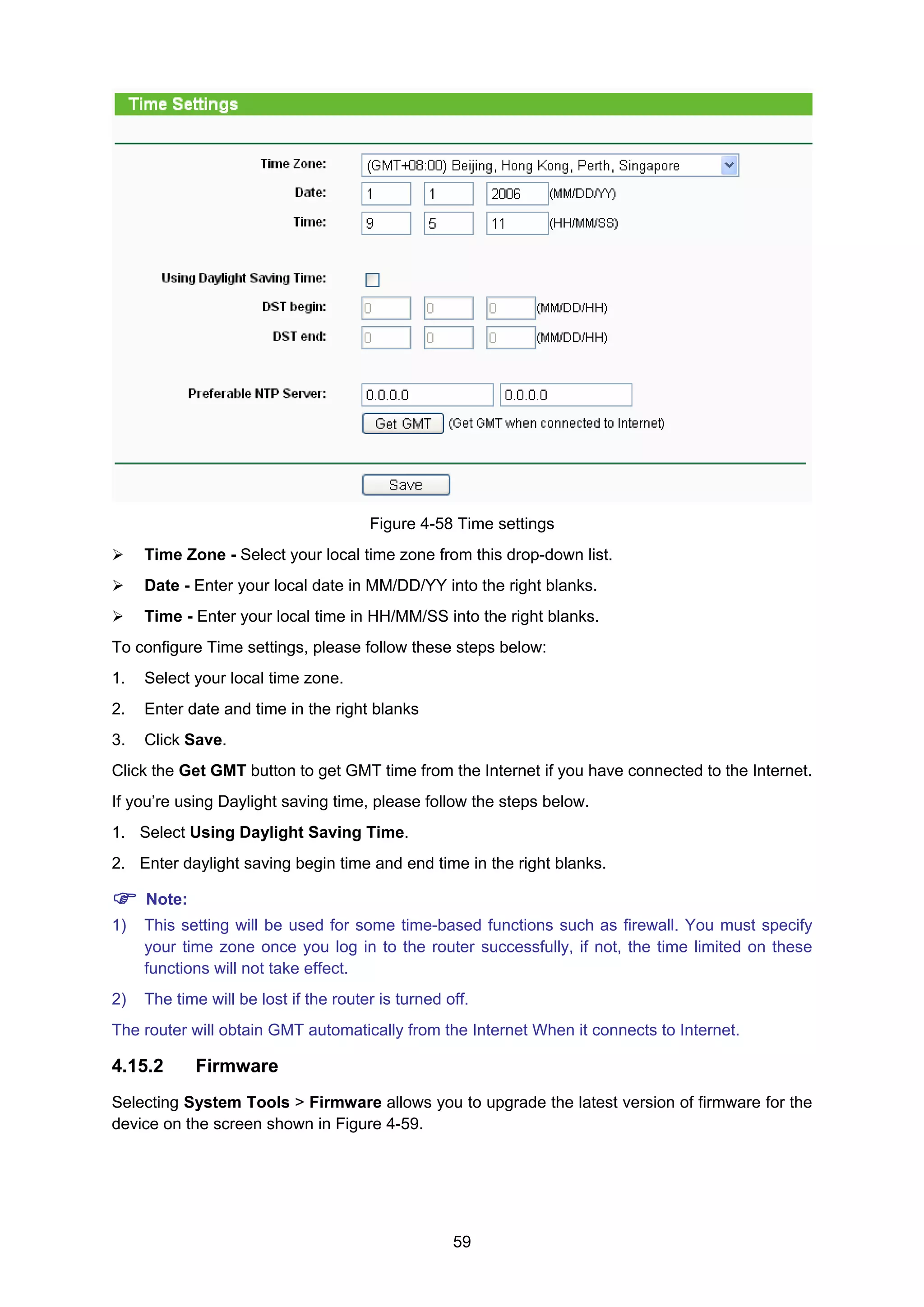
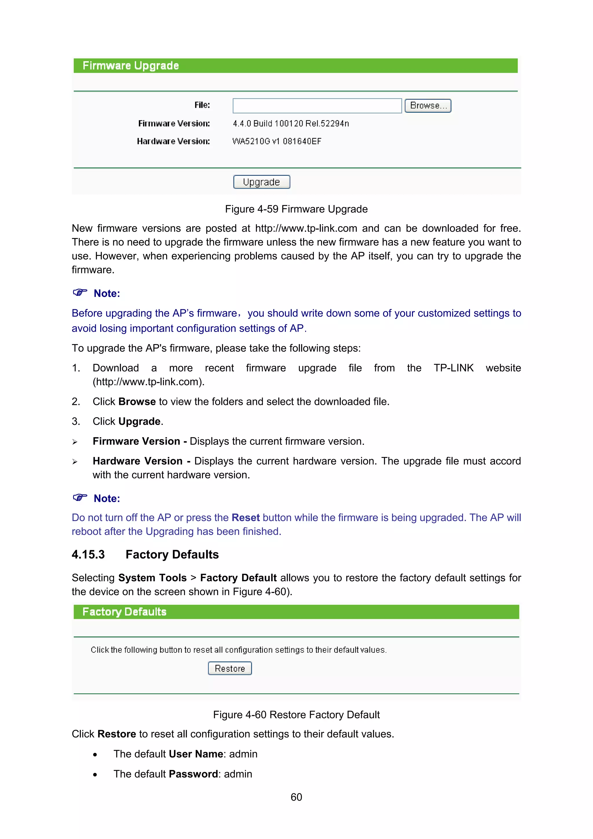
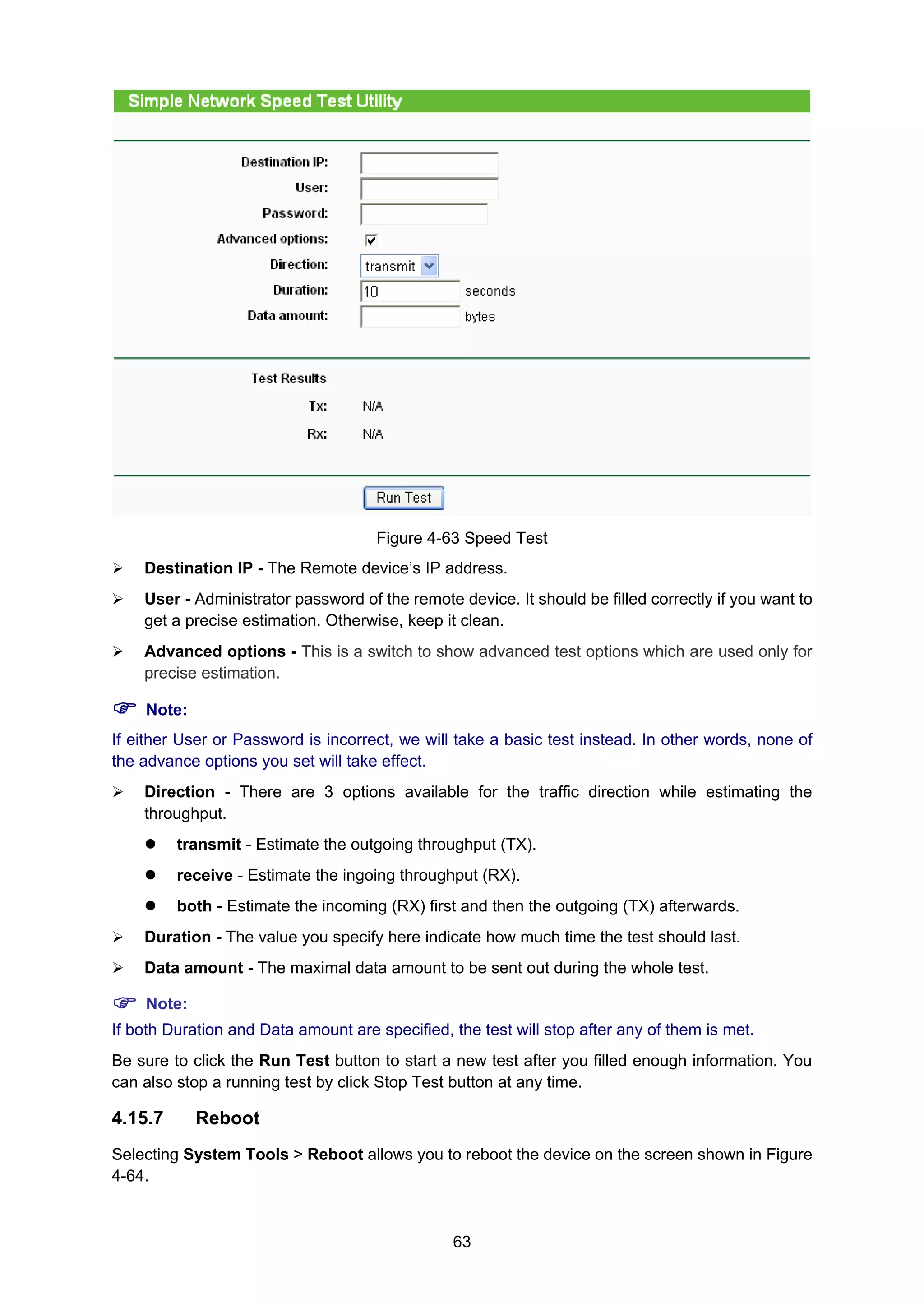
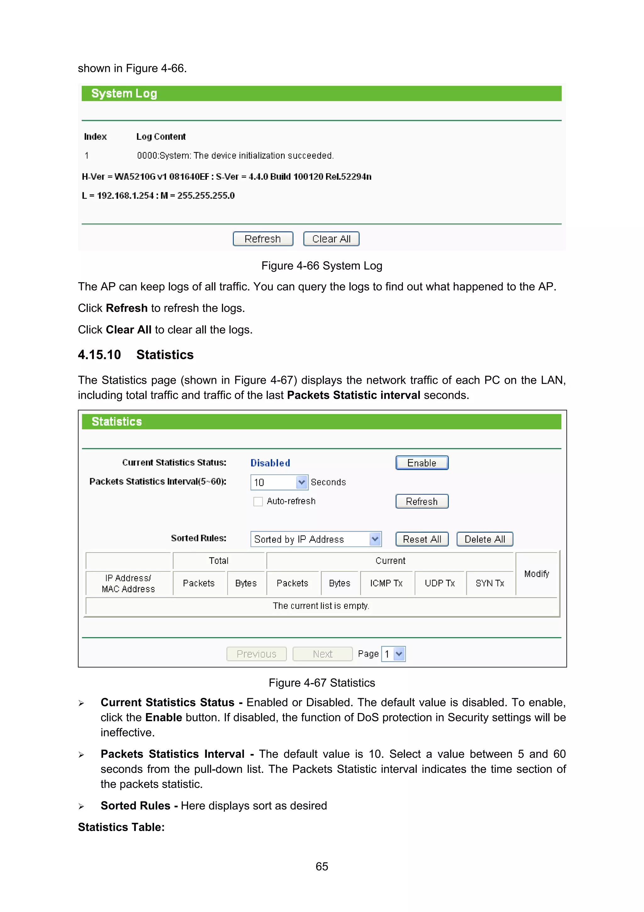
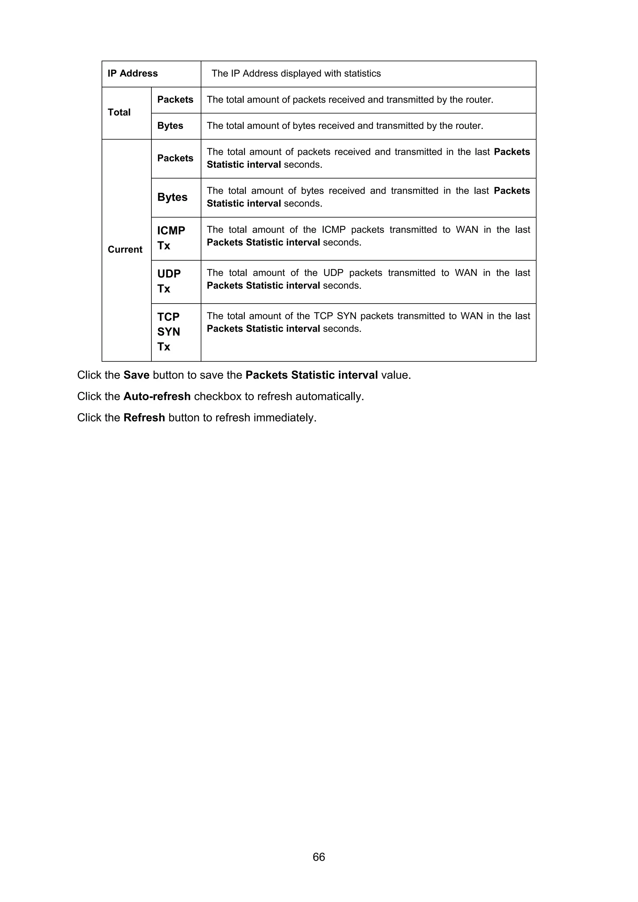
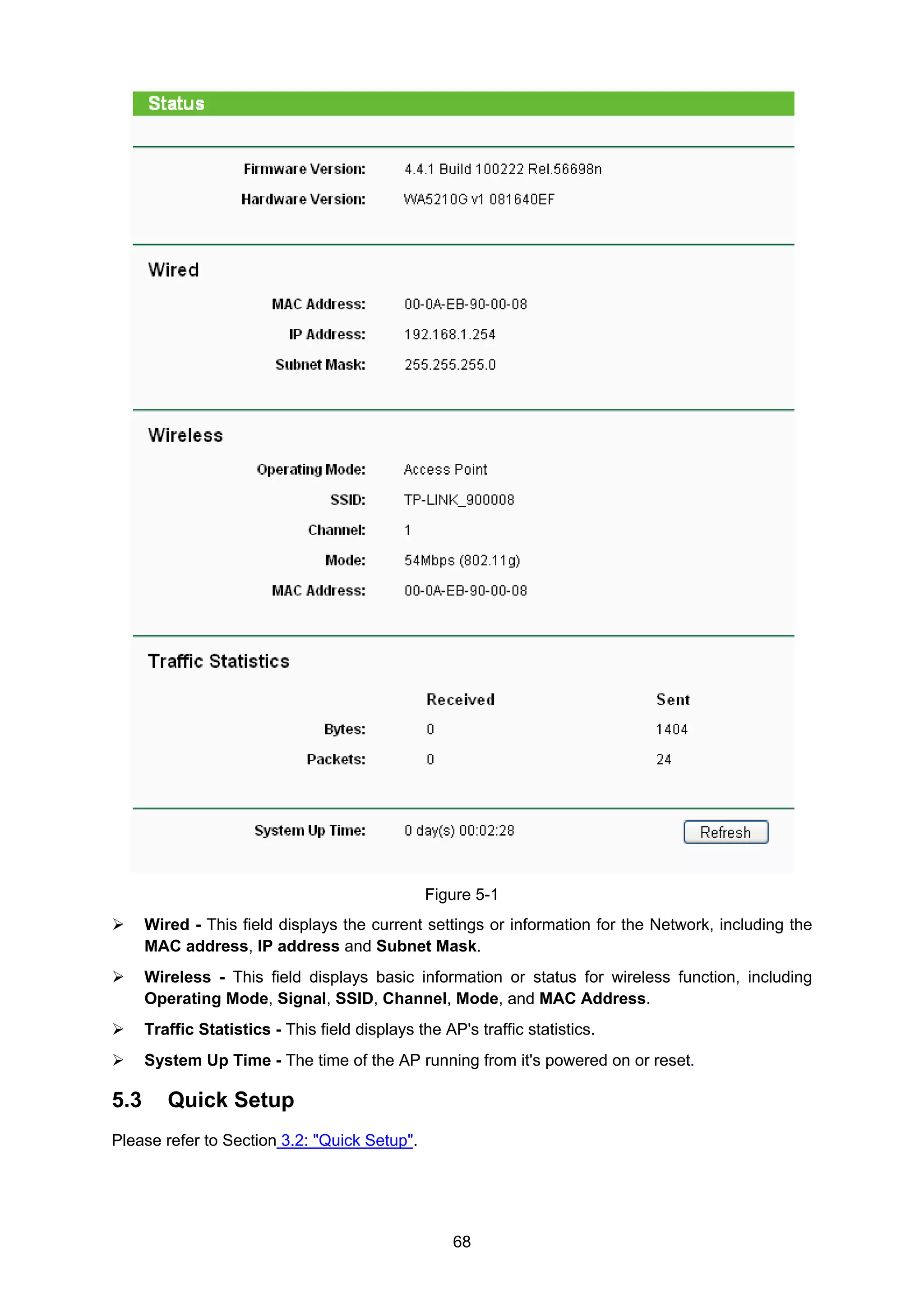
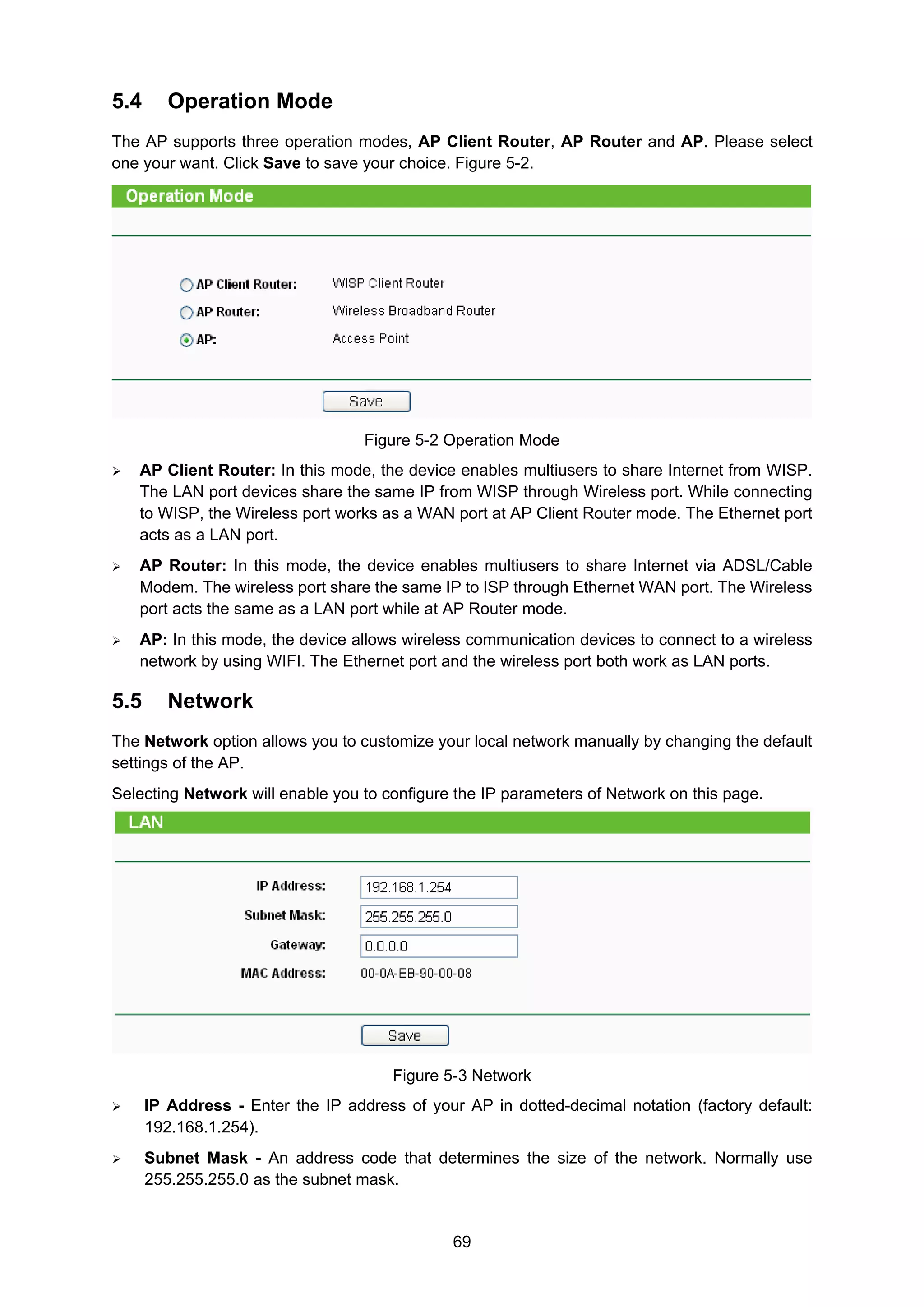
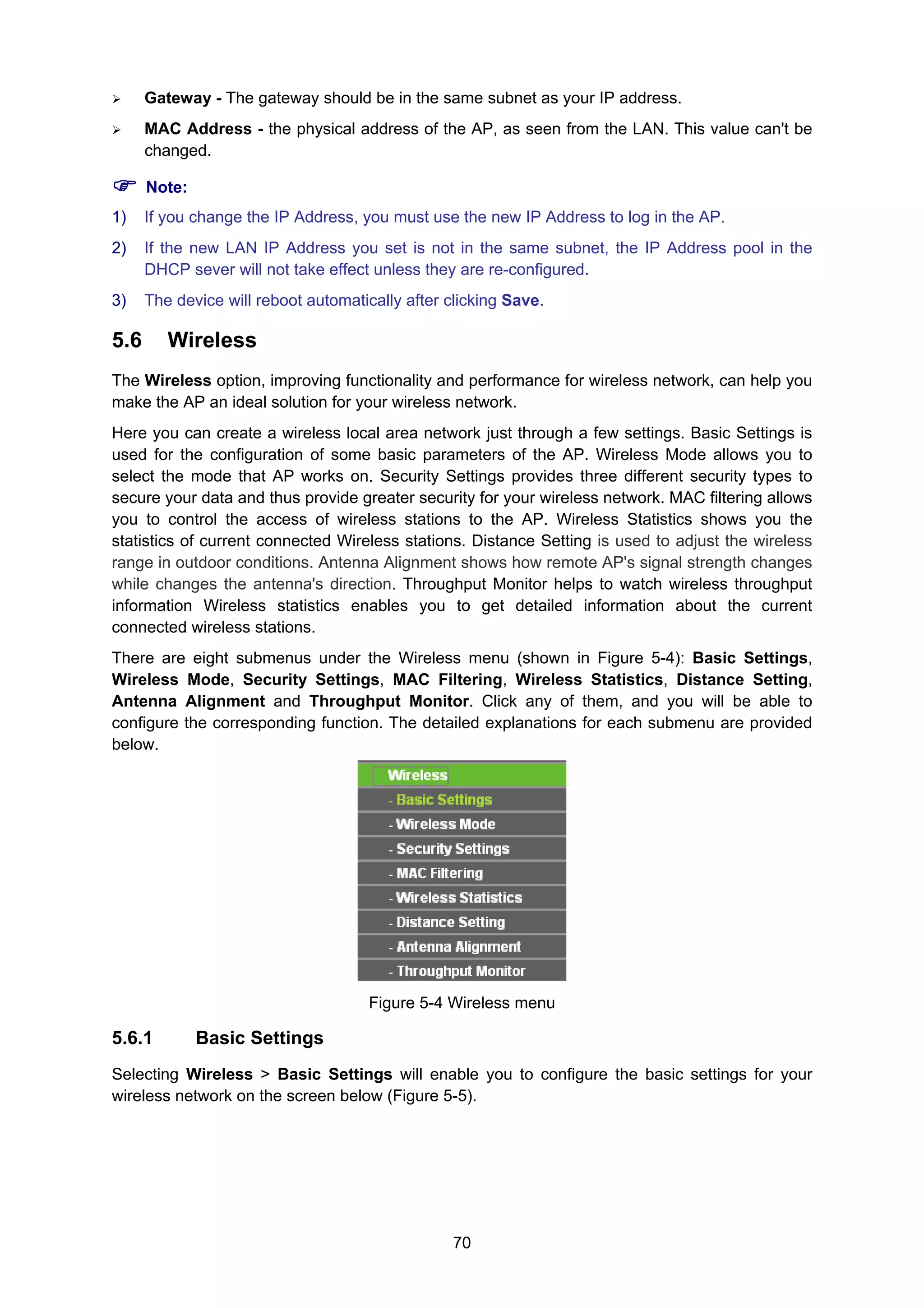
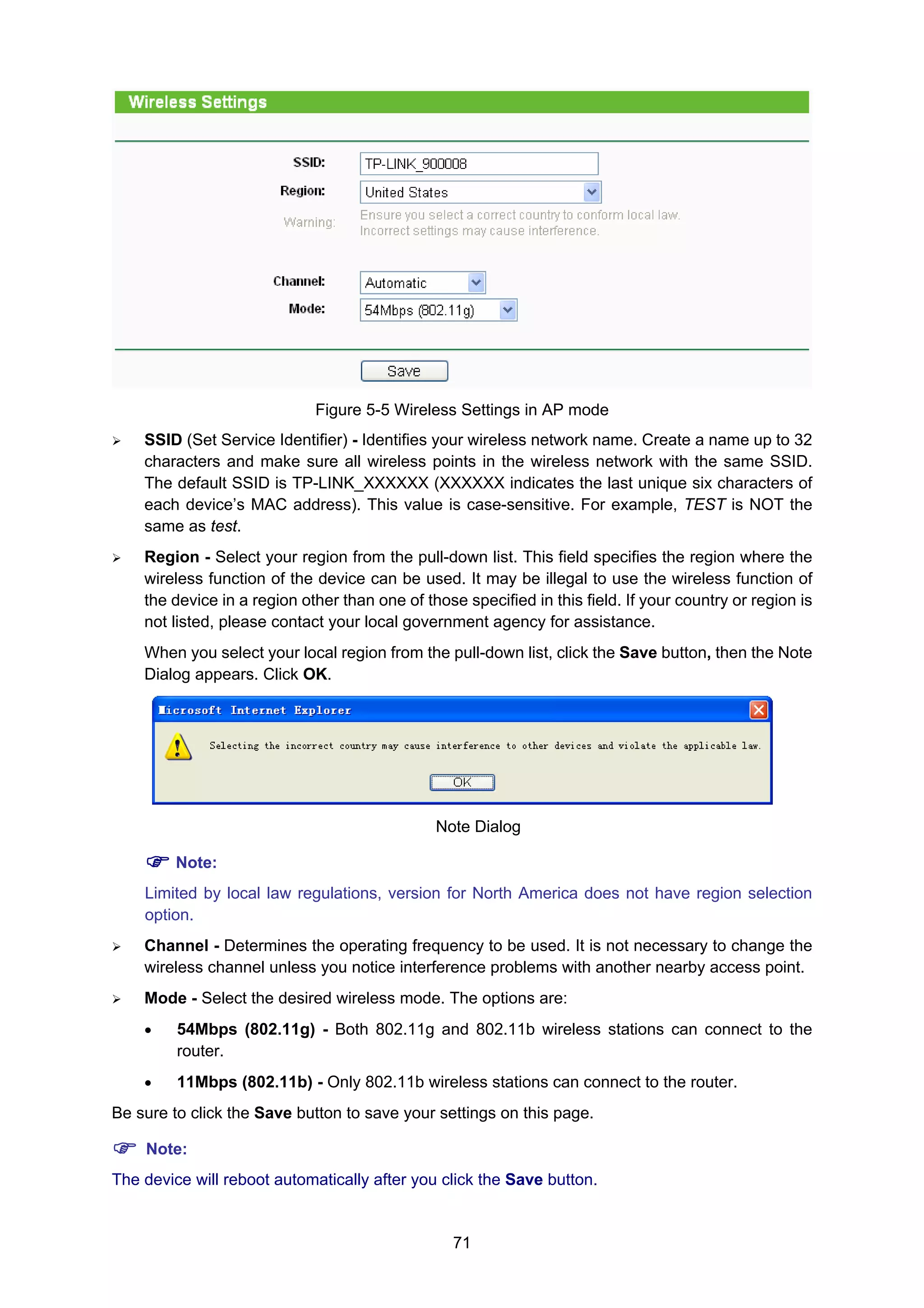
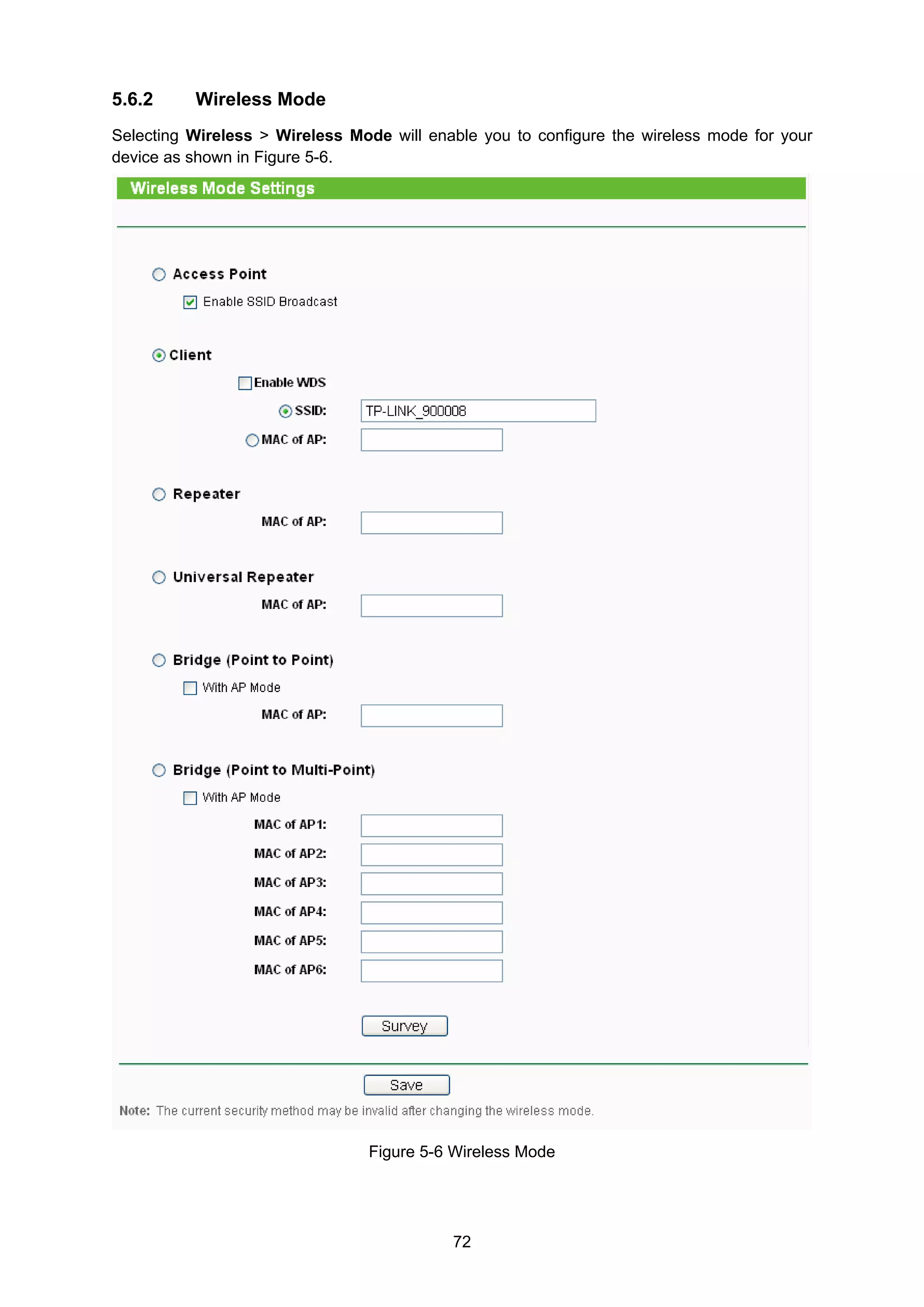
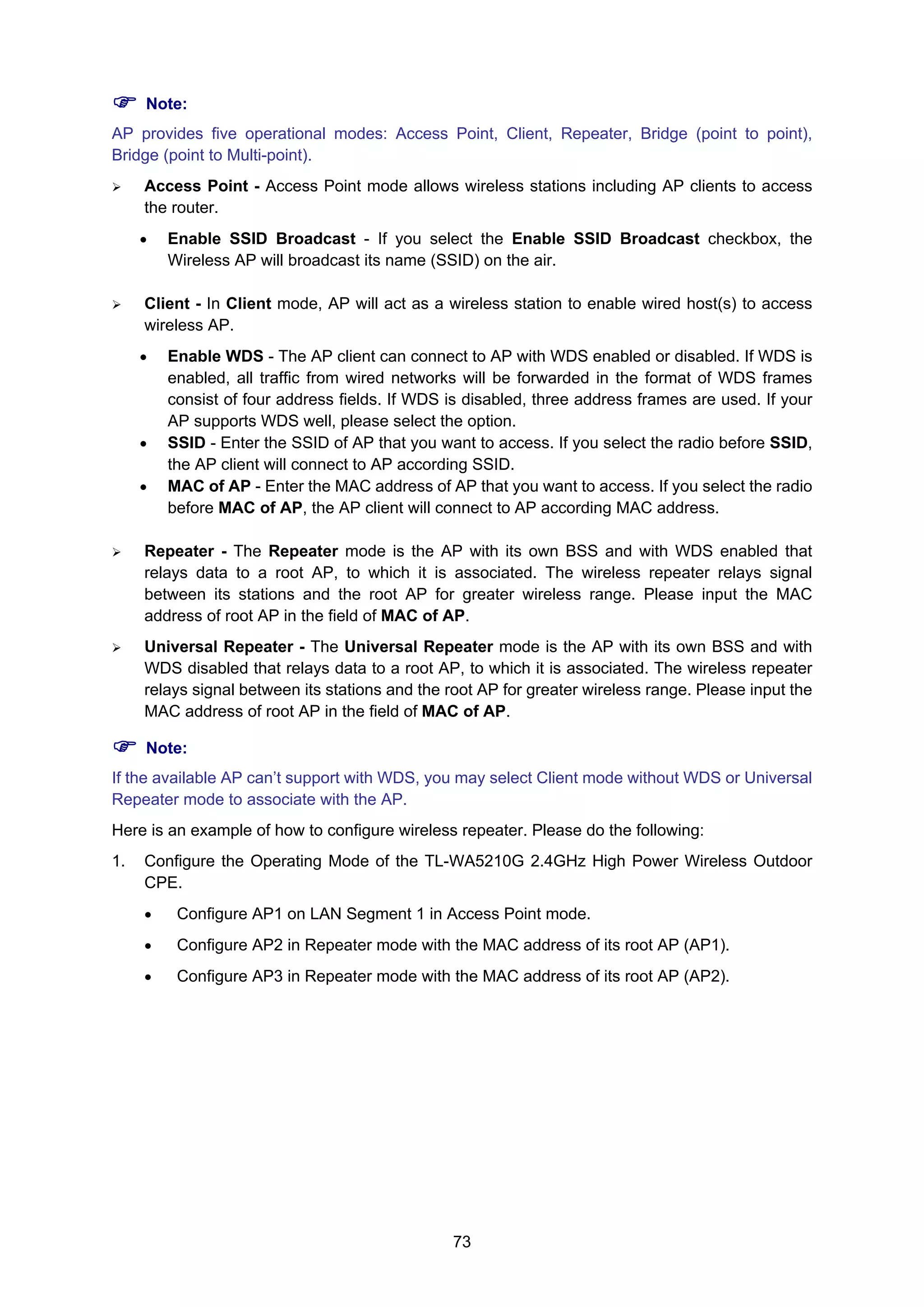
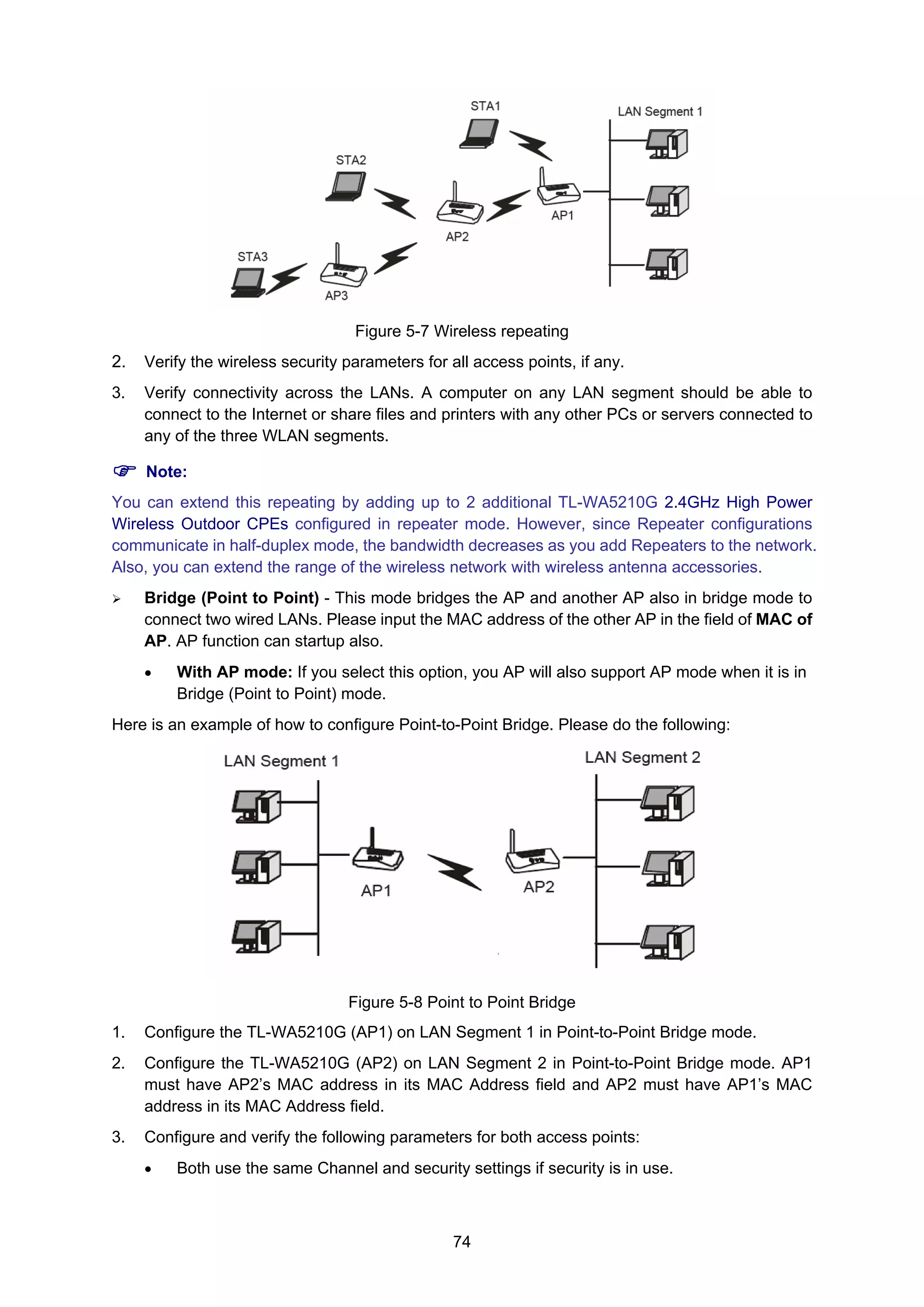
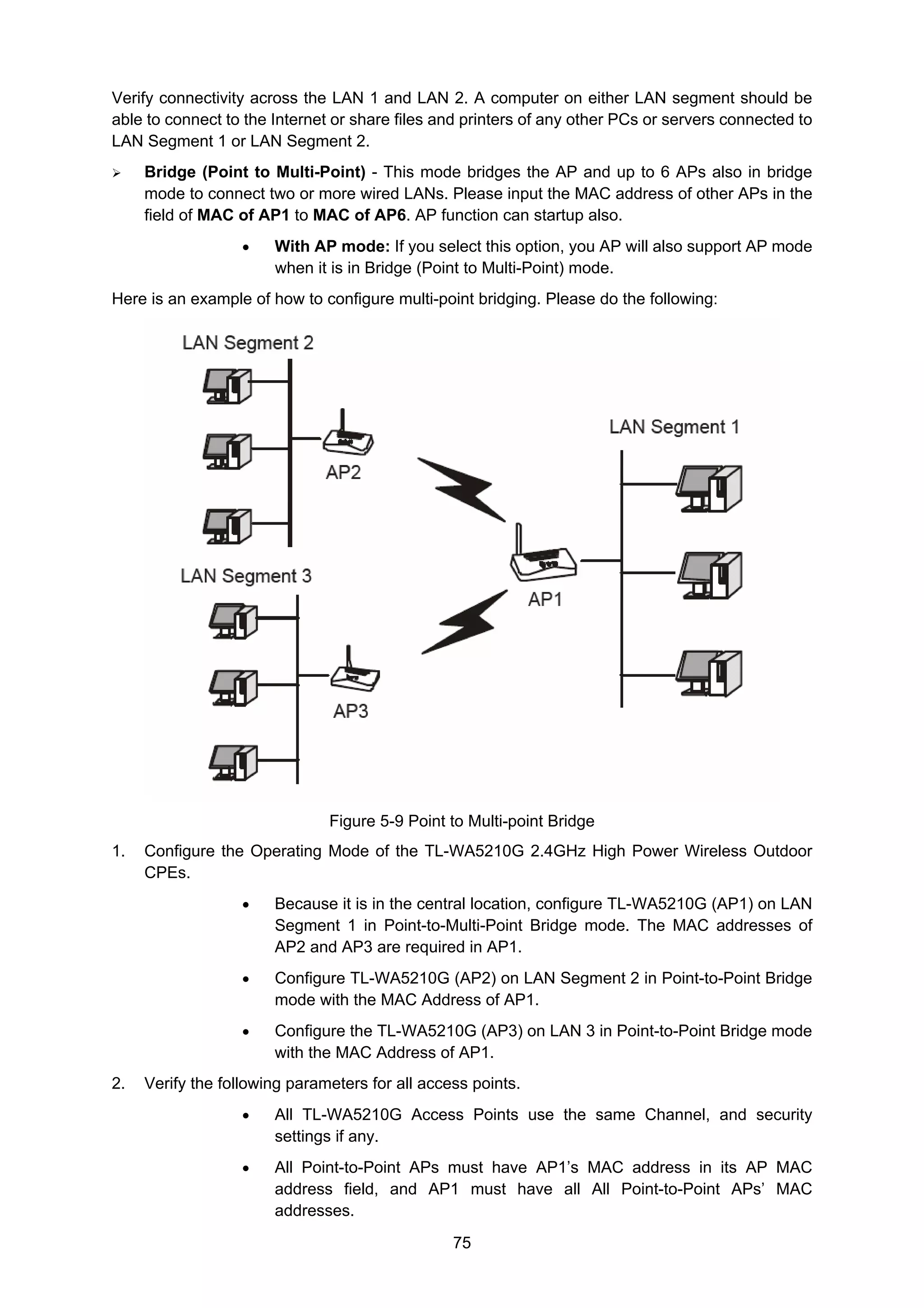
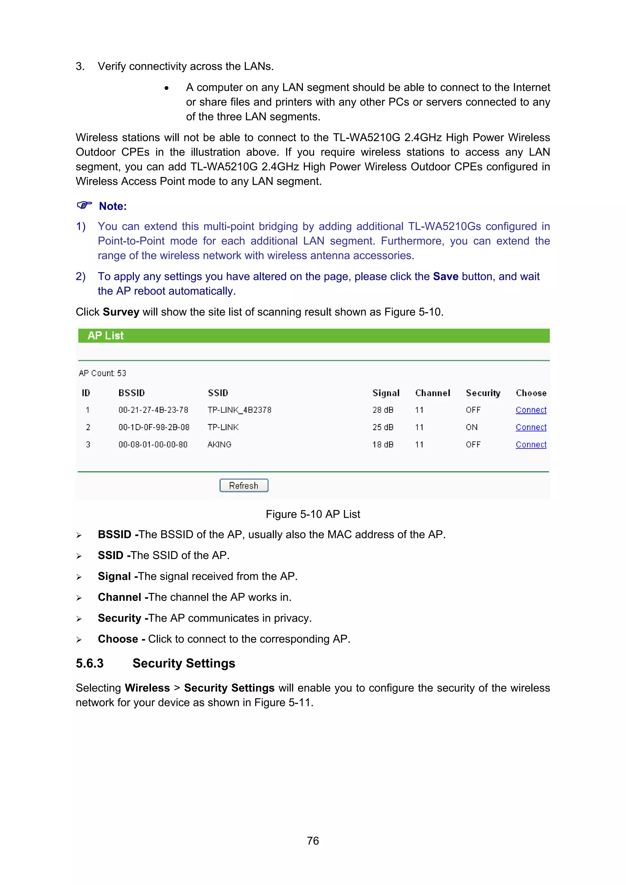
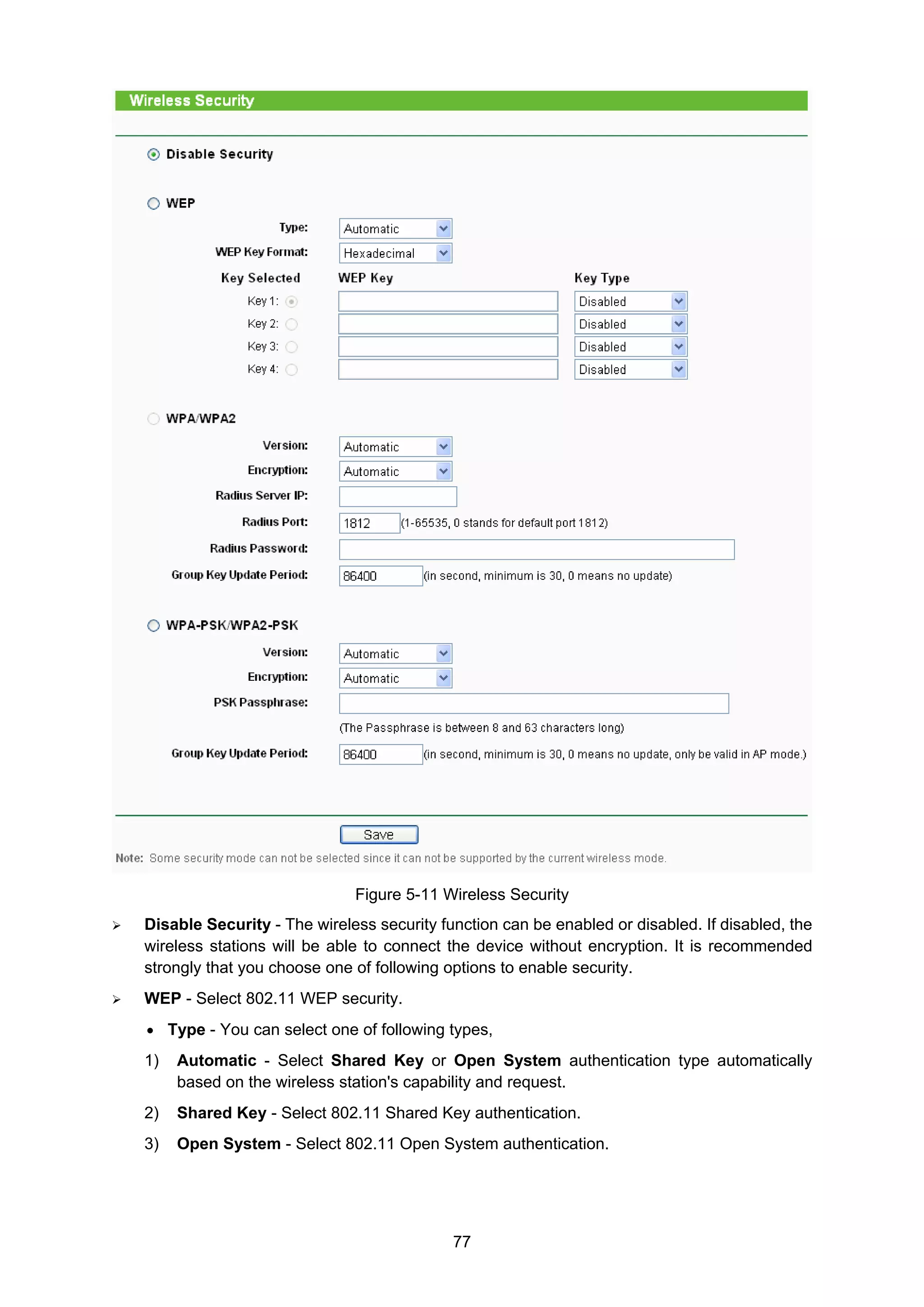
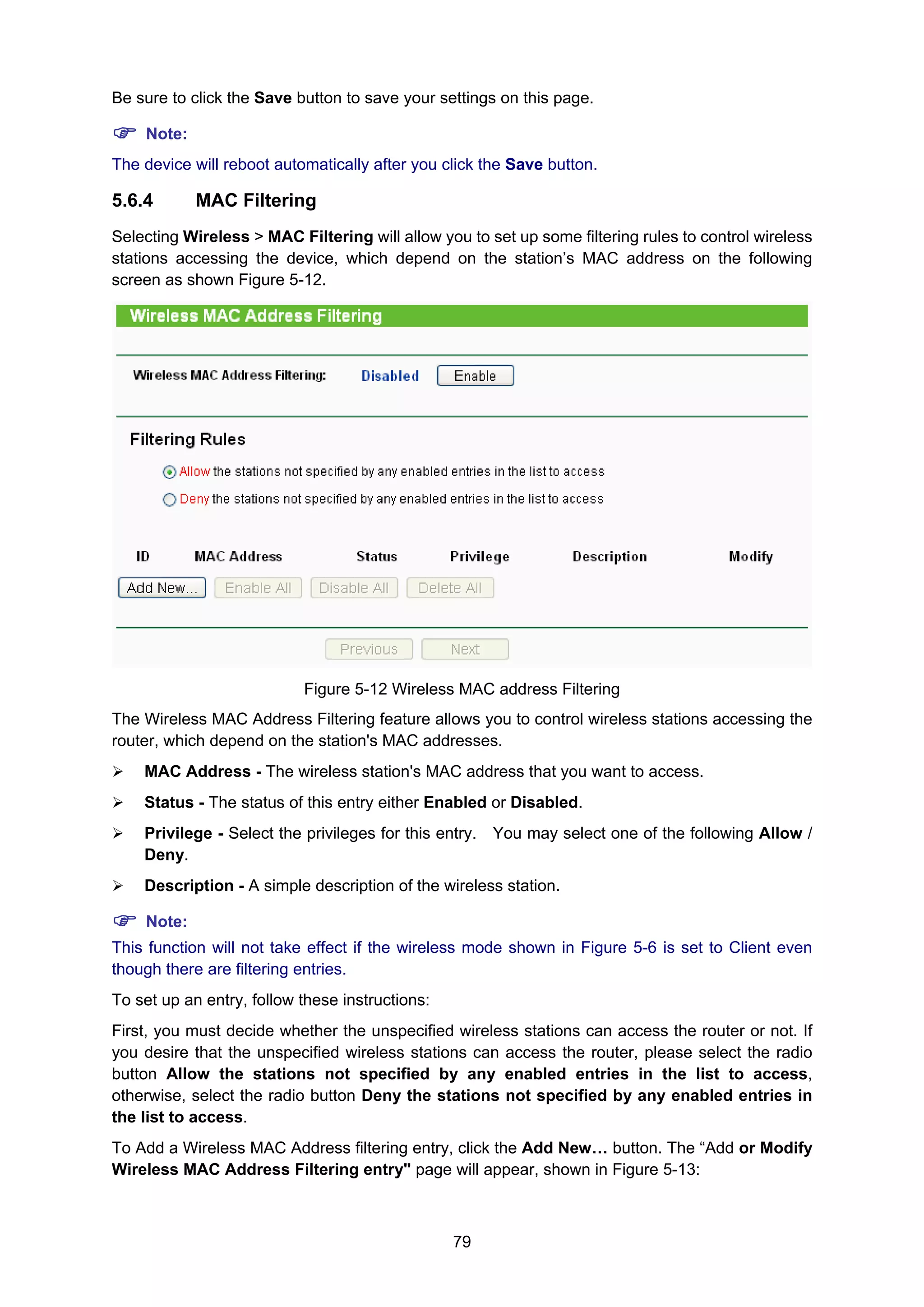
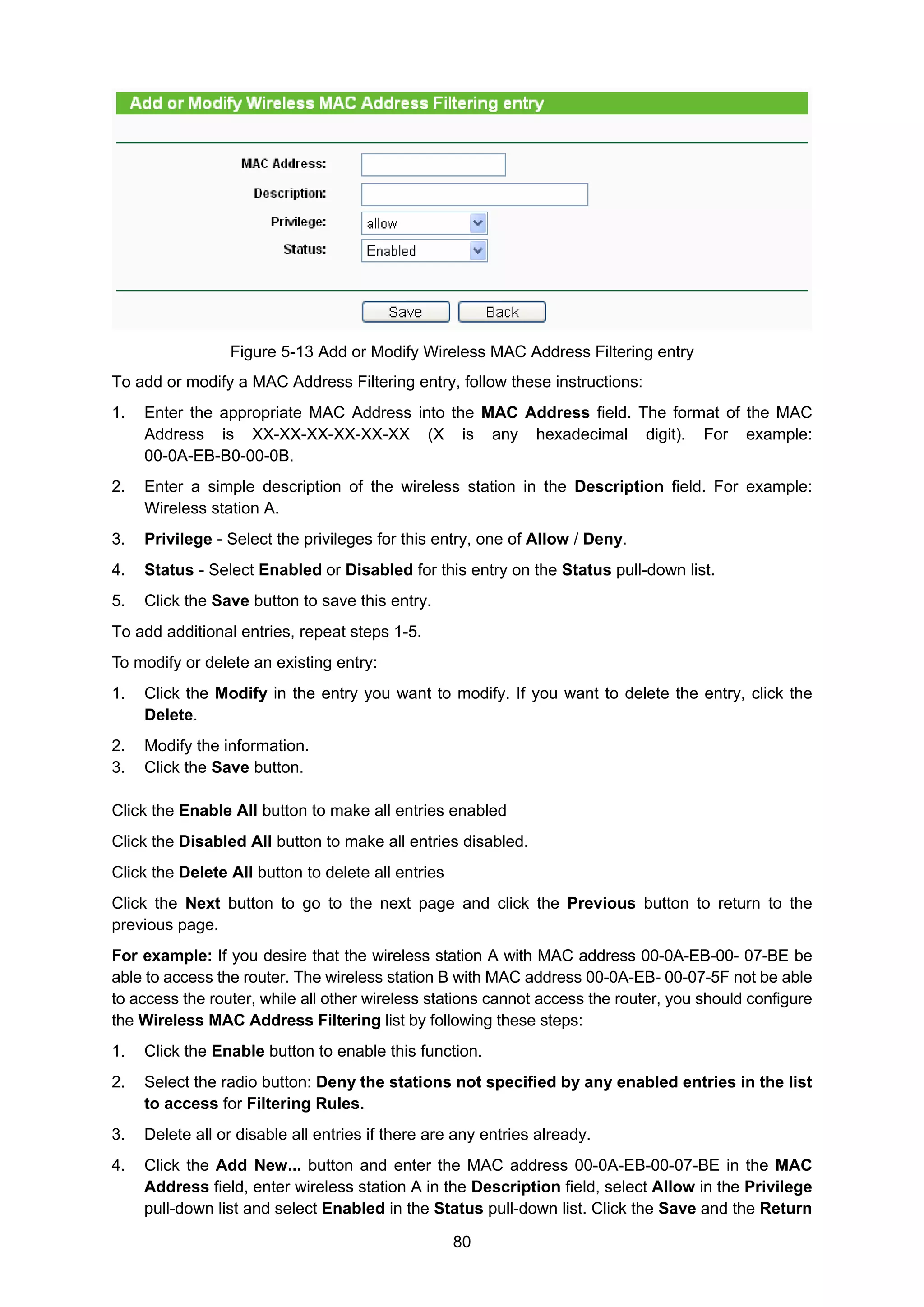
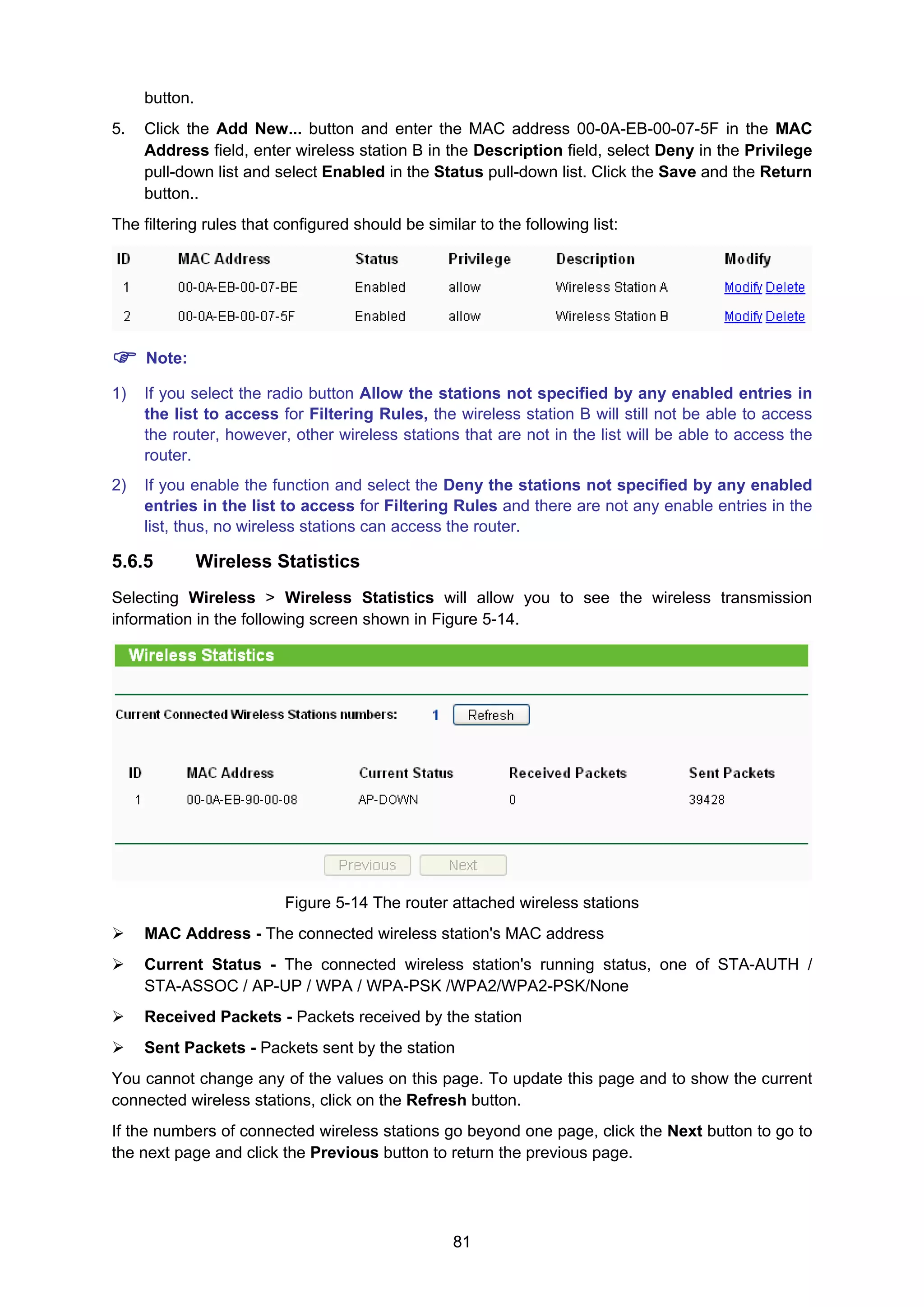
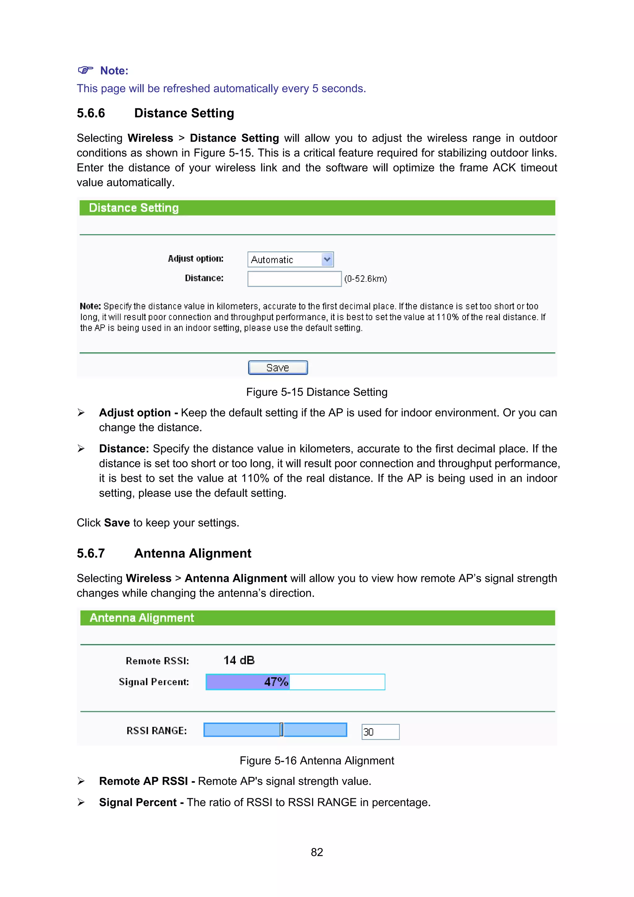
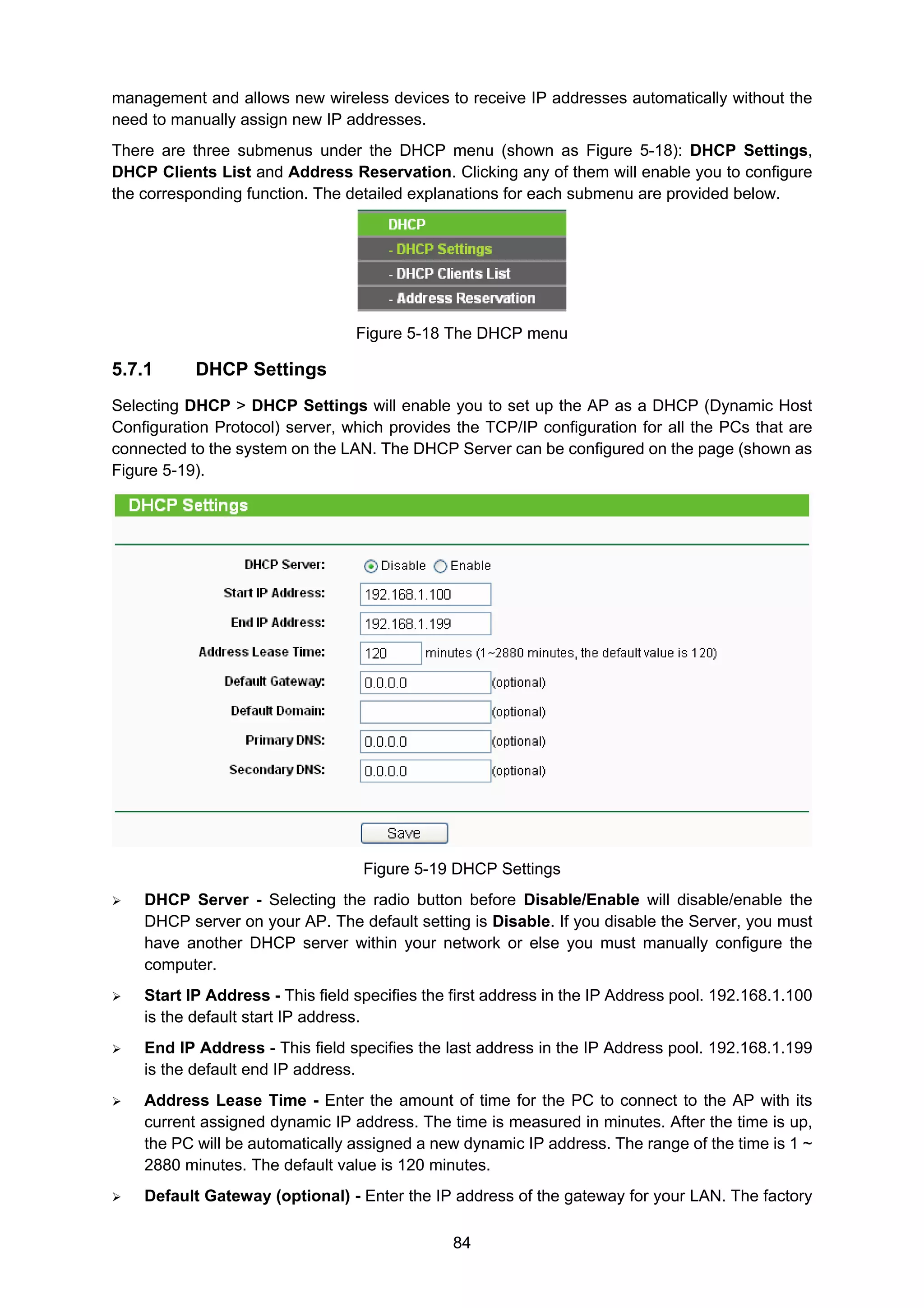
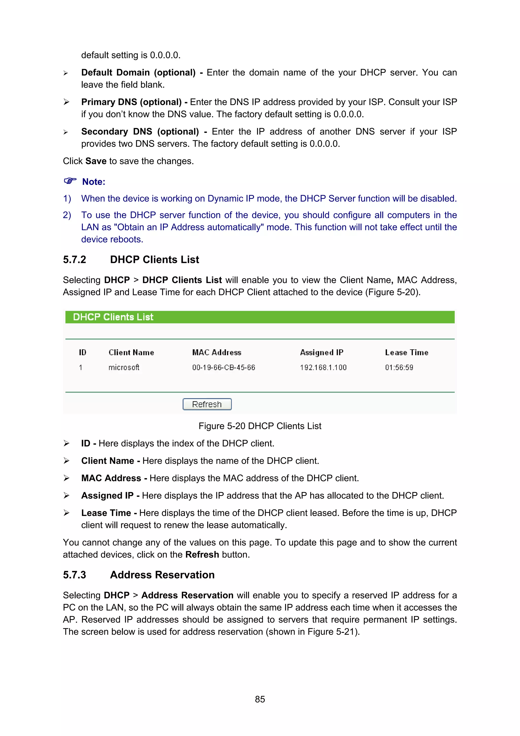
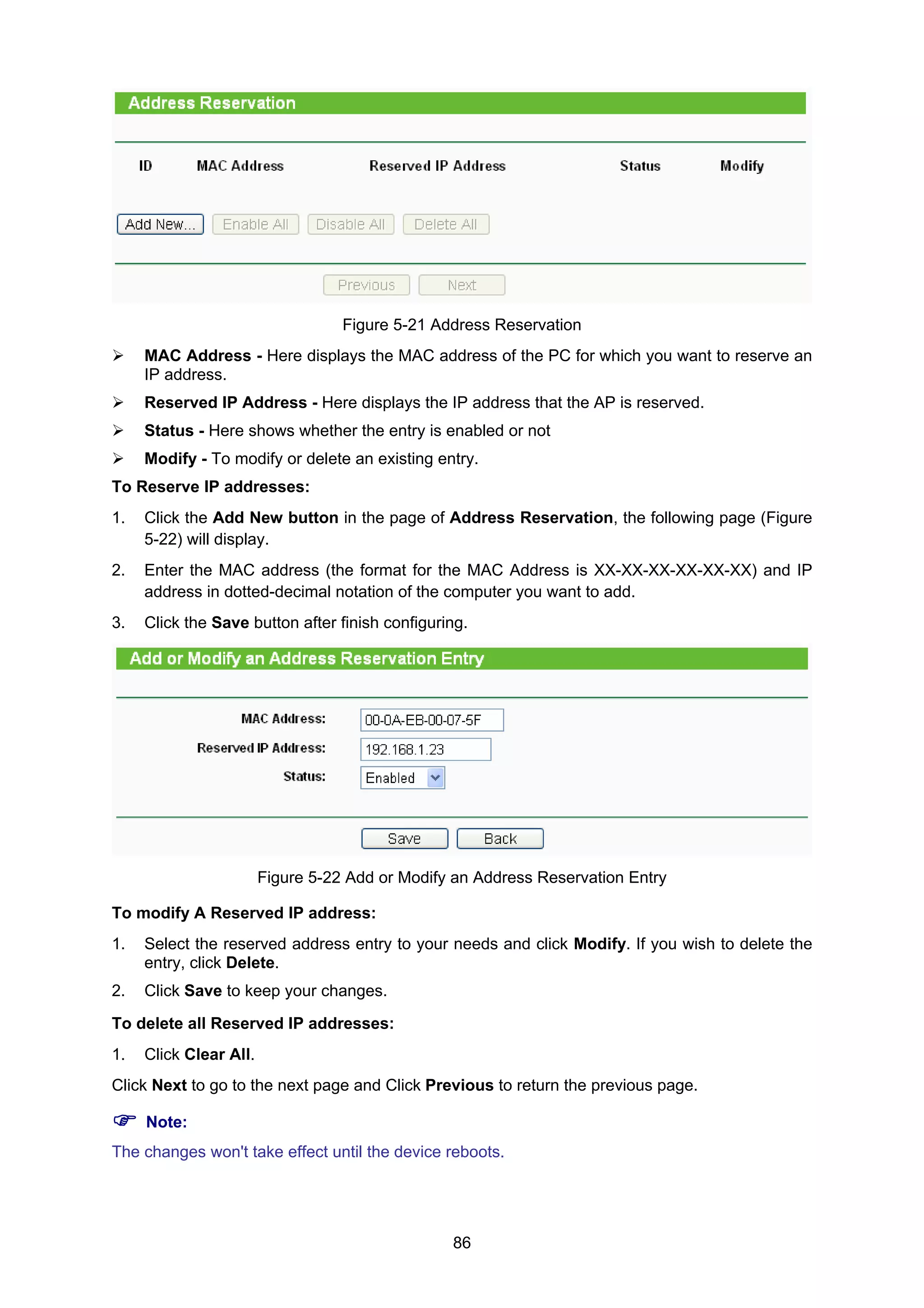
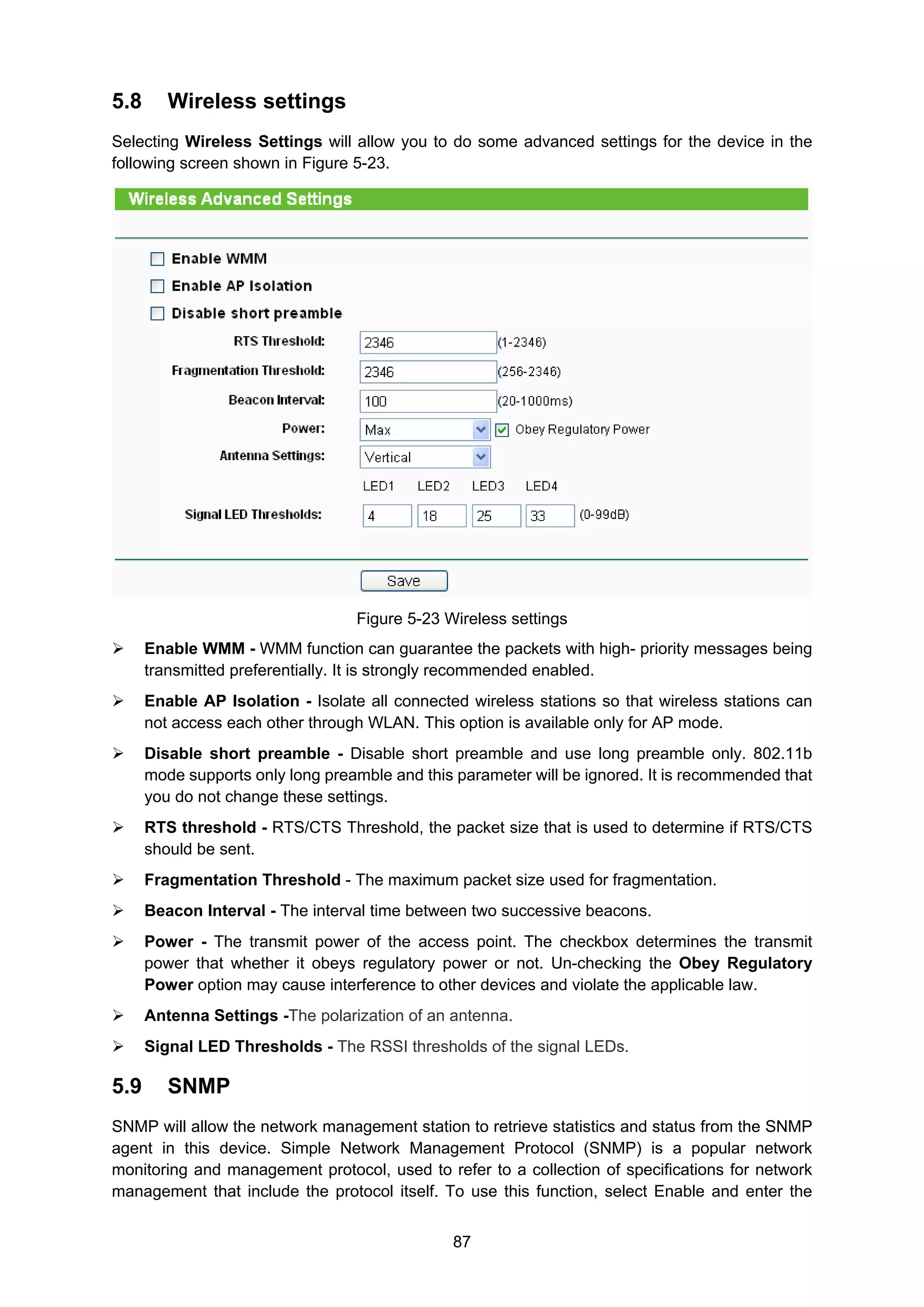
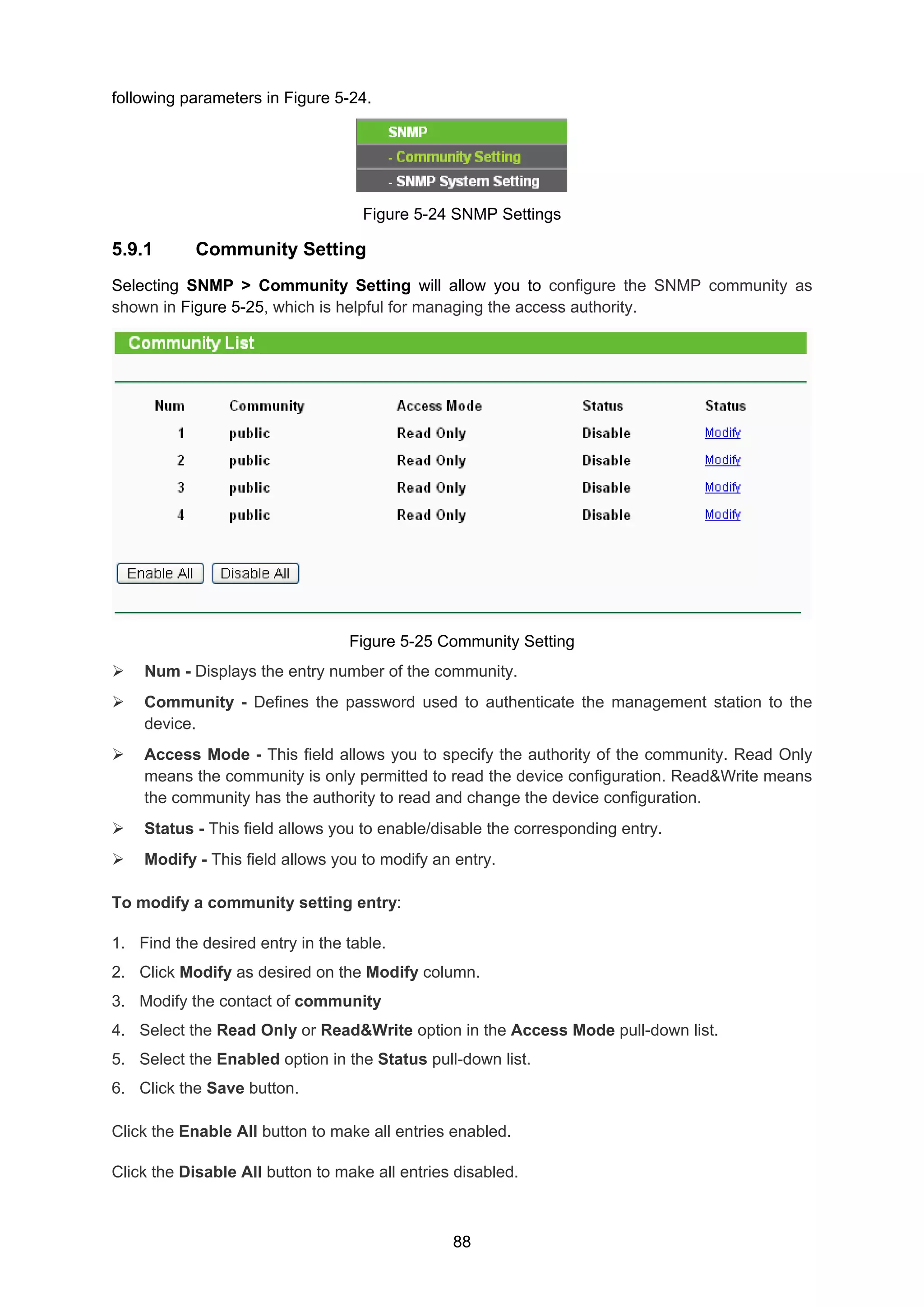
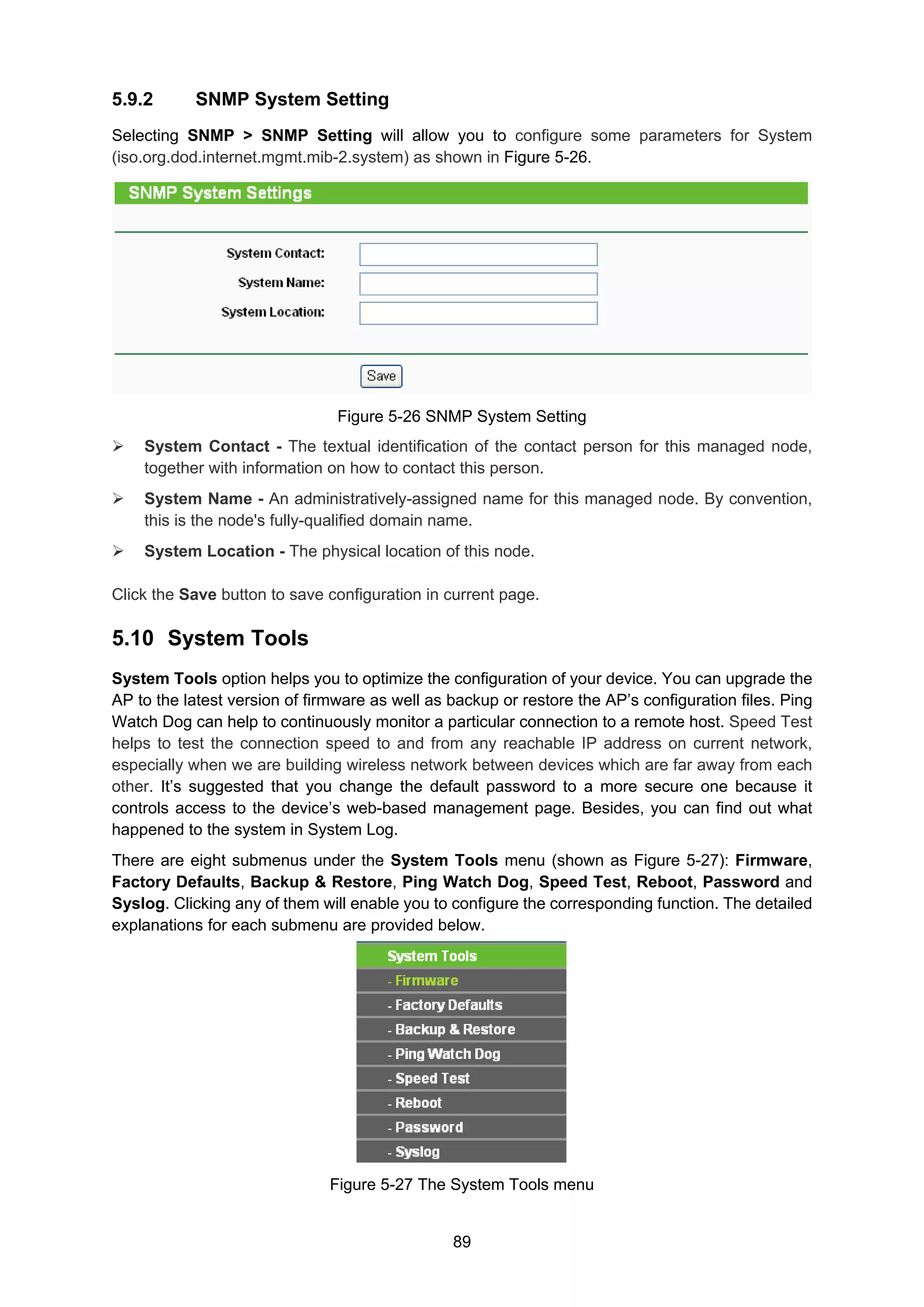
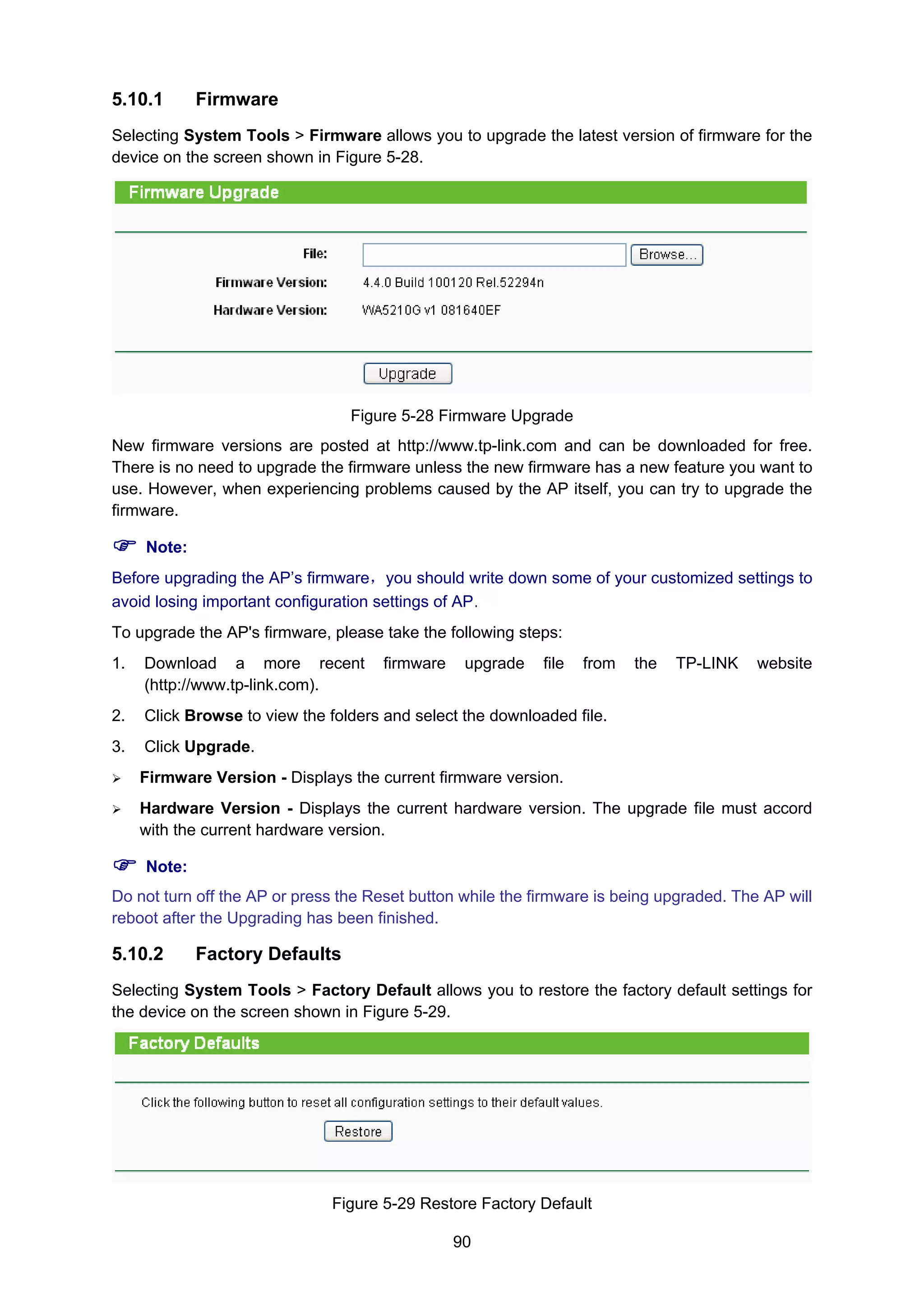
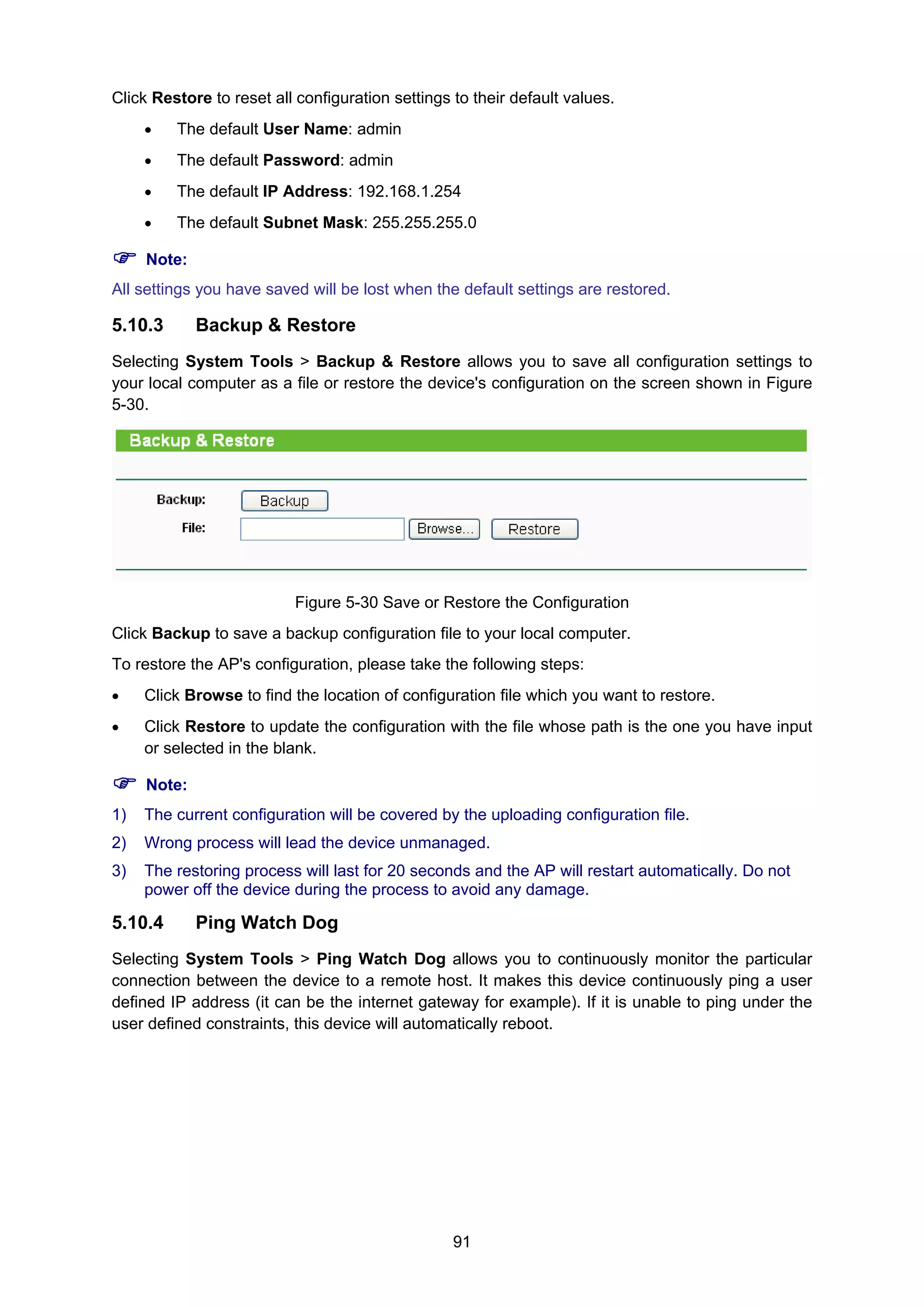
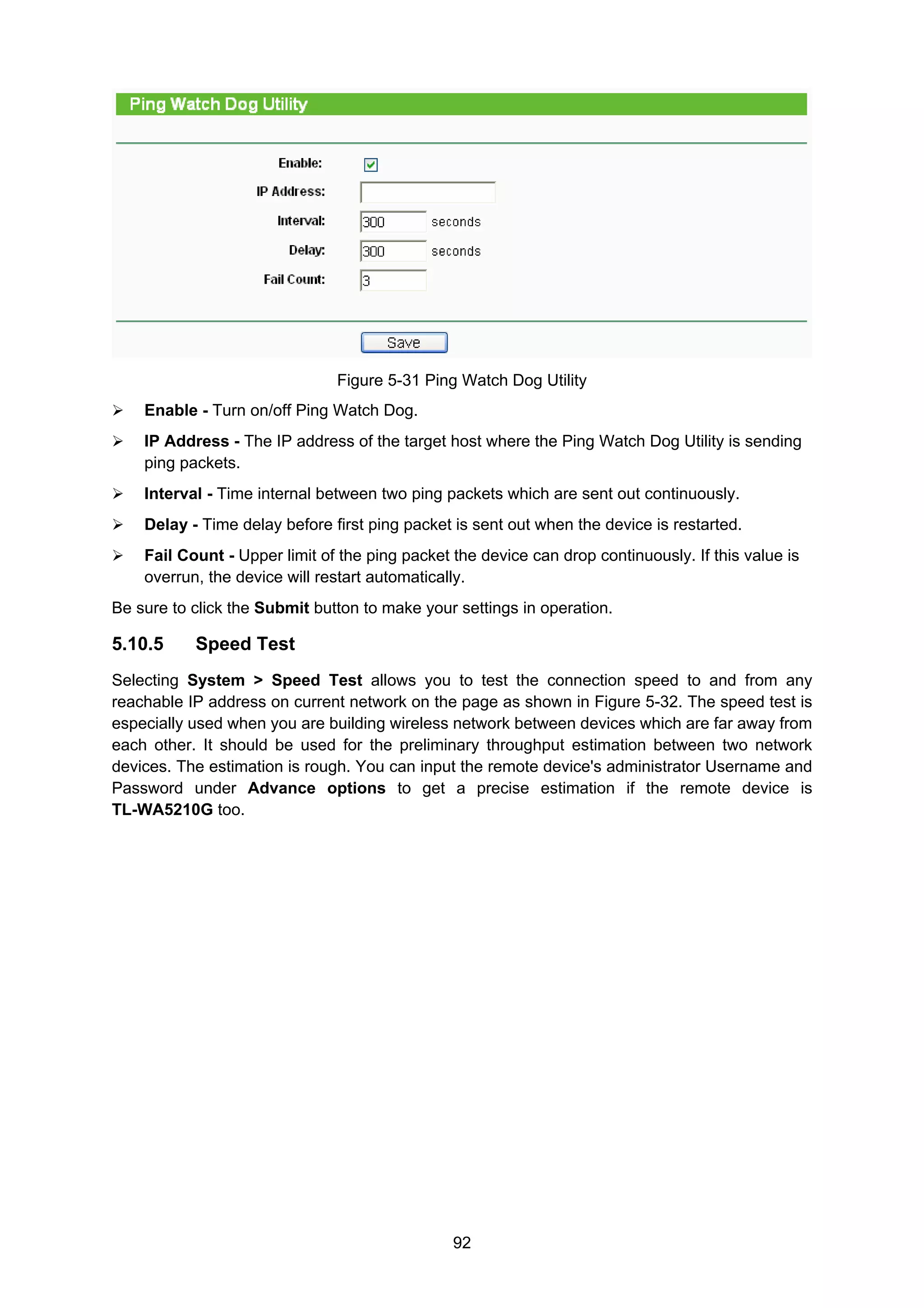
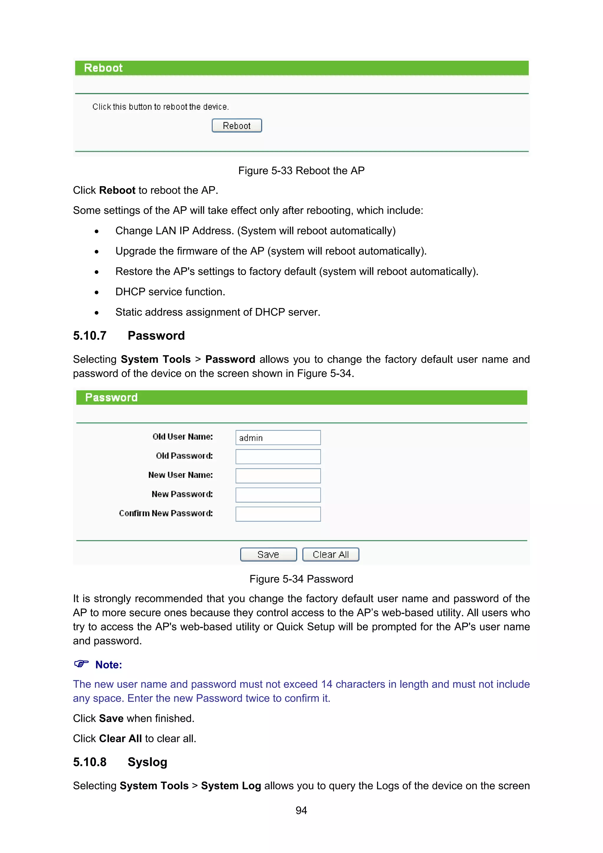
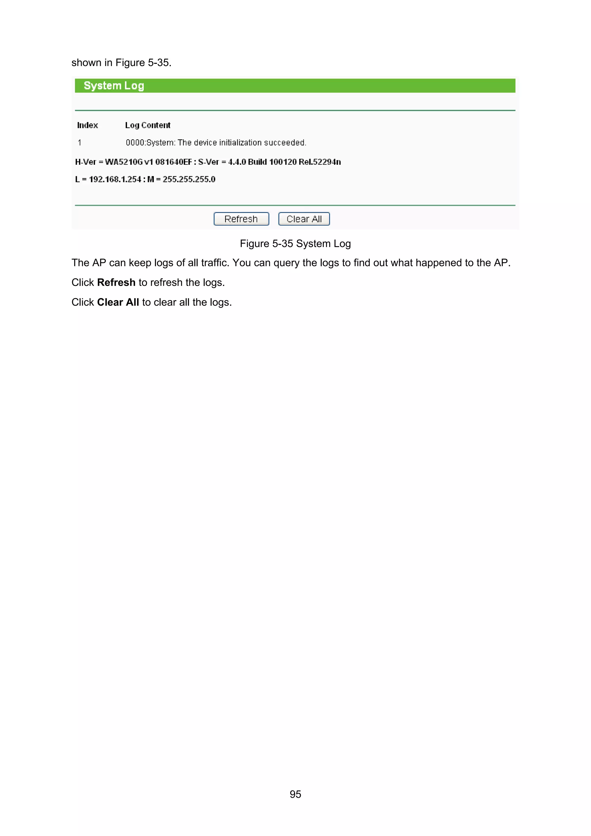
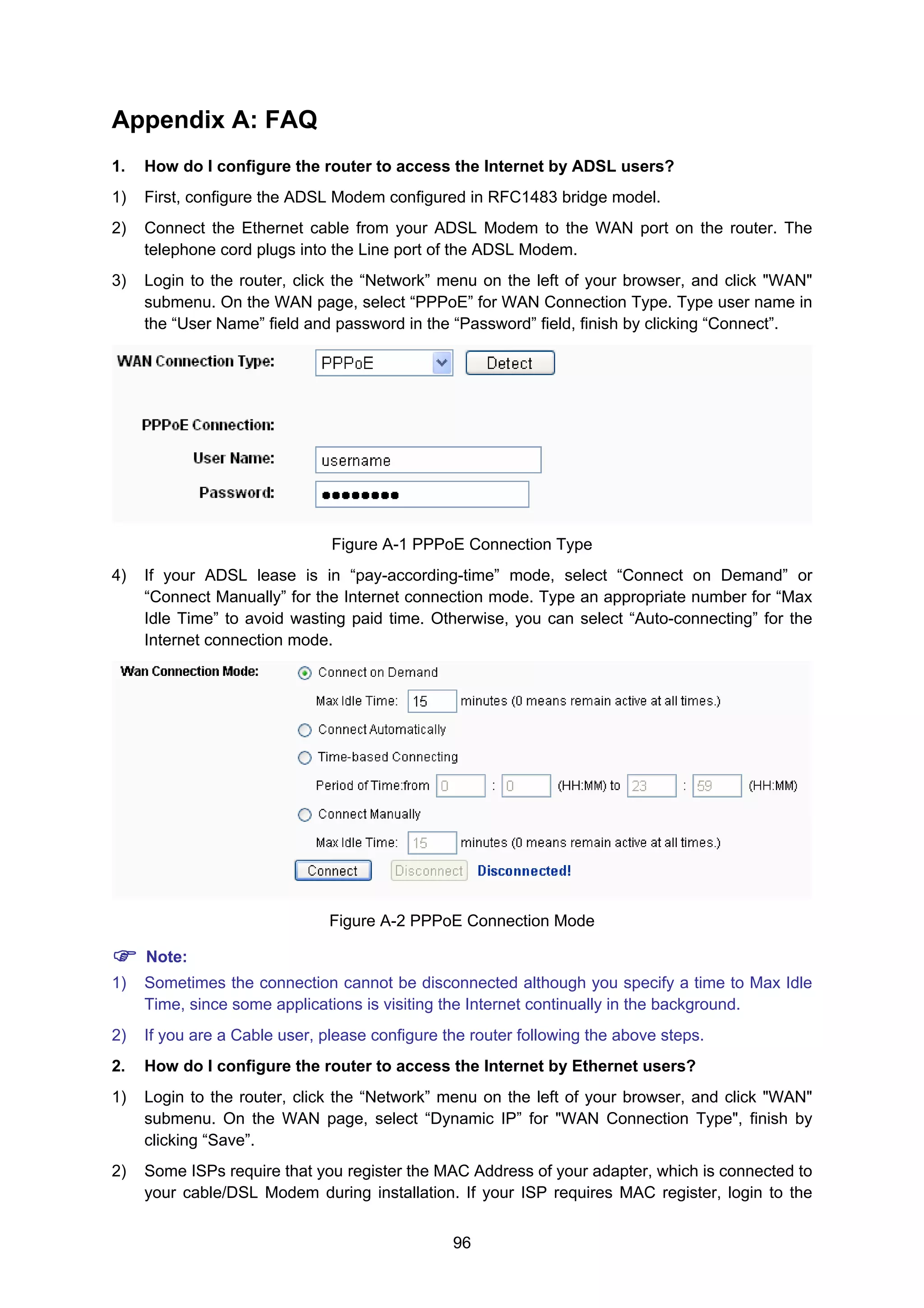
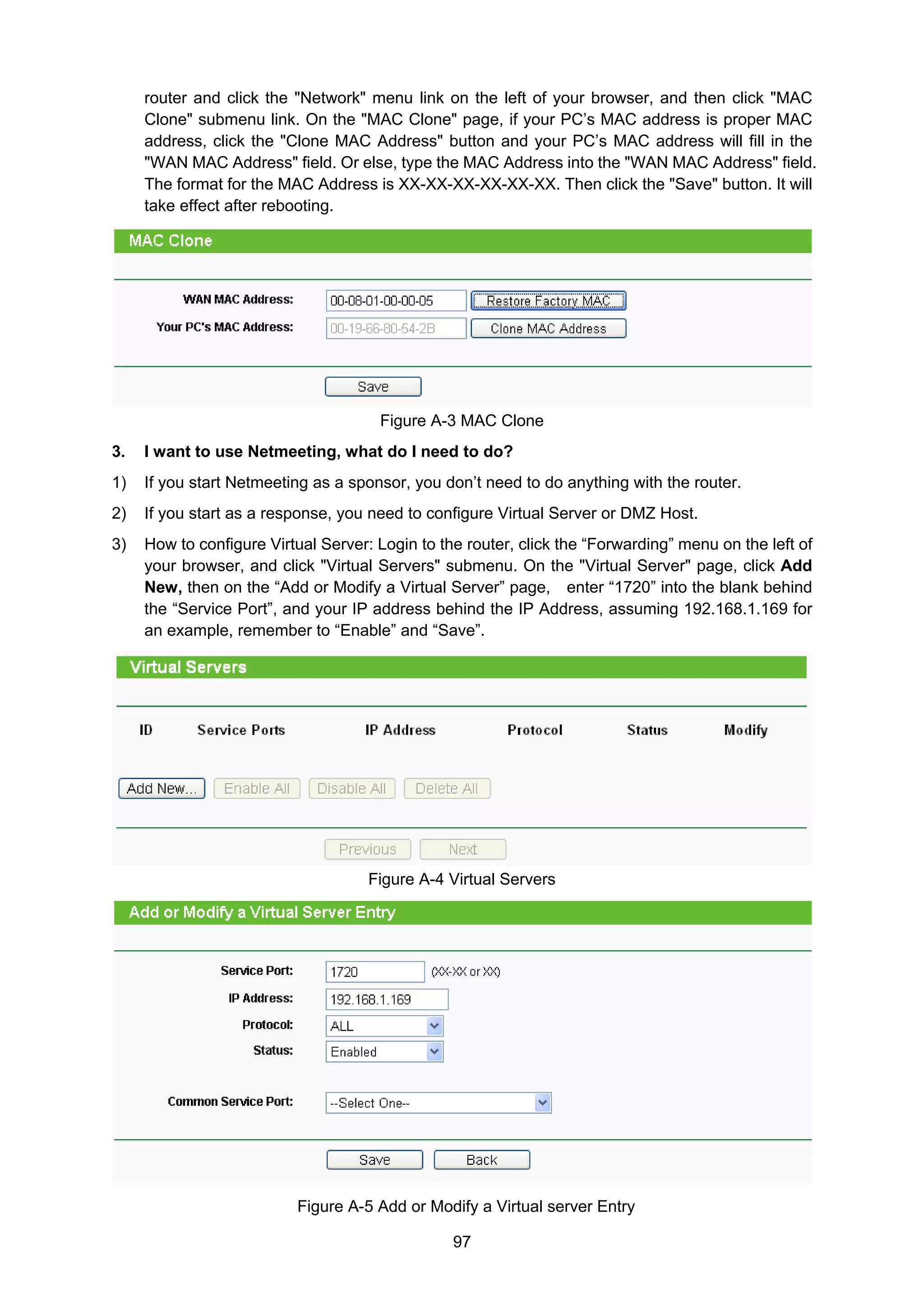
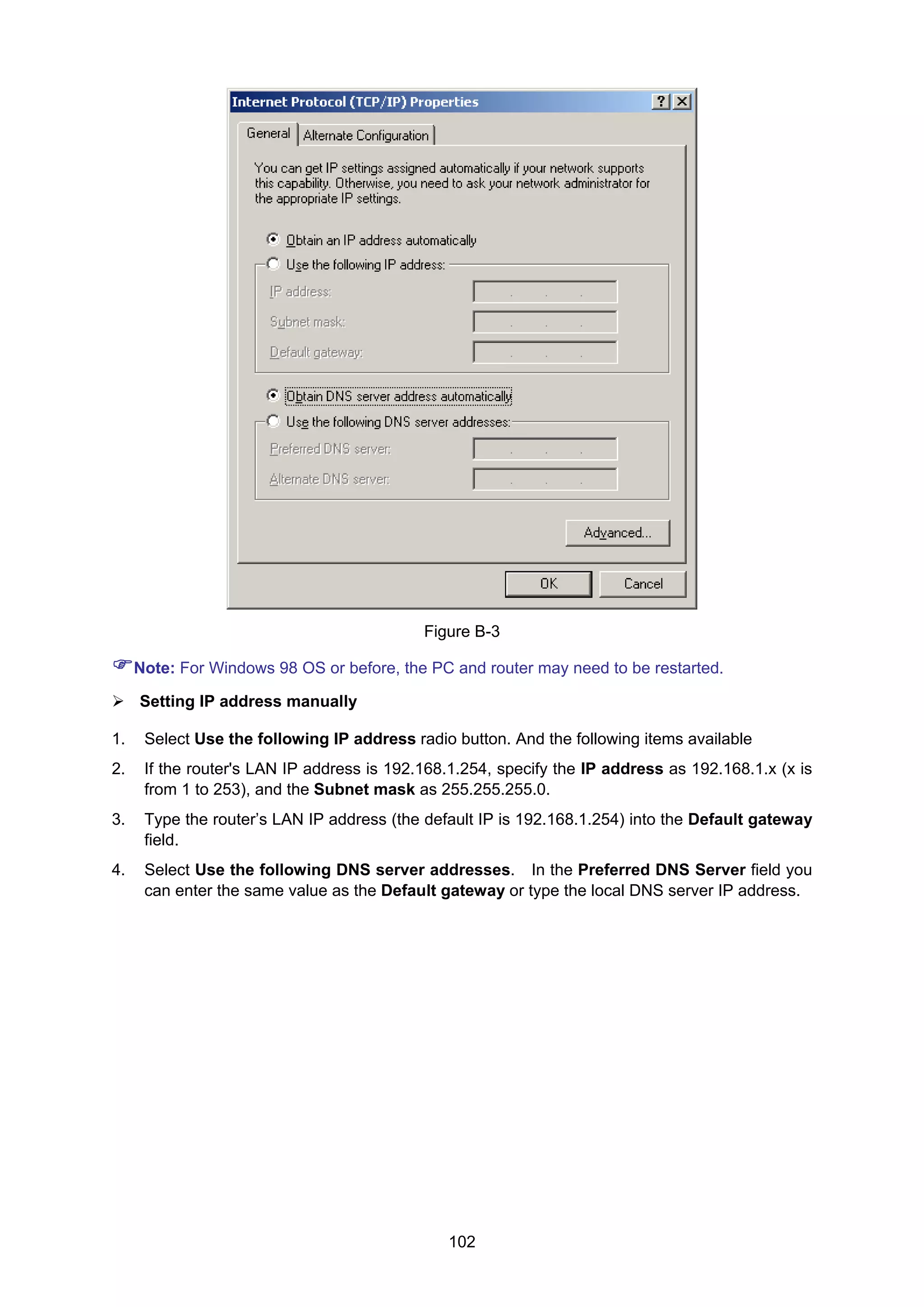
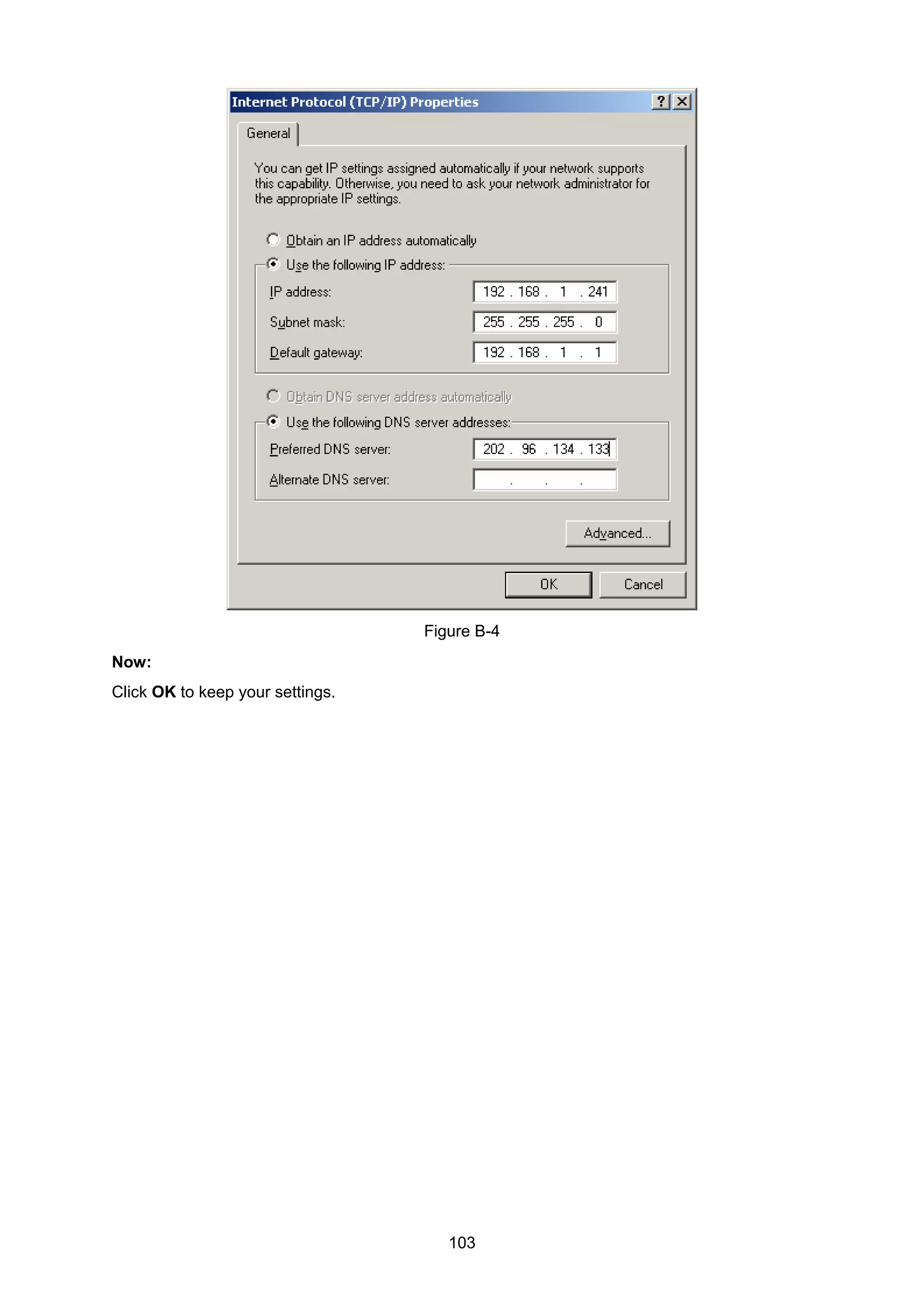
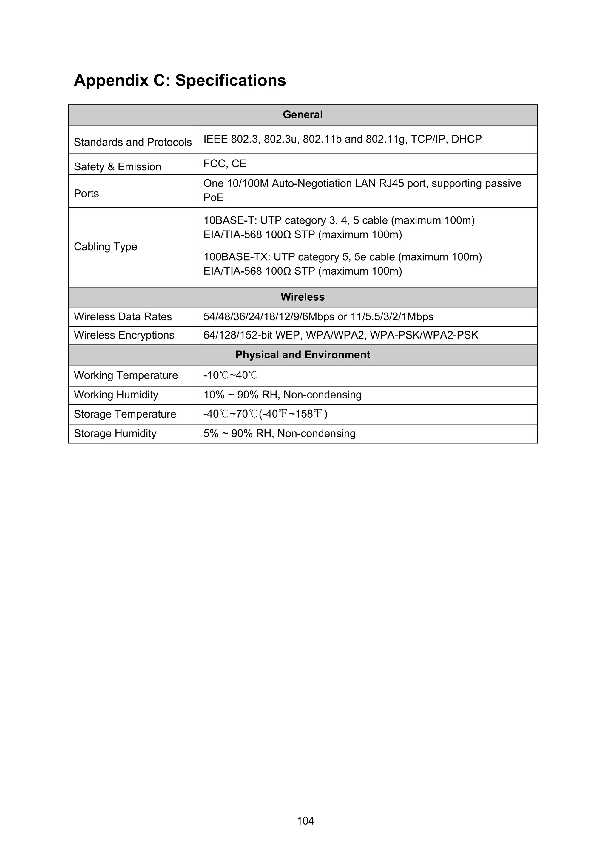
This document provides product specifications and compliance information for the TL-WA5210G 2.4GHz High Power Wireless Outdoor CPE device. It includes details on FCC compliance for radio frequency exposure, CE marking compliance, the device's technical characteristics, and contact information for TP-LINK TECHNOLOGIES CO., LTD. The document contains instructions on installing and setting up the device, its LED indicators, interfaces, system requirements and supported operation modes.
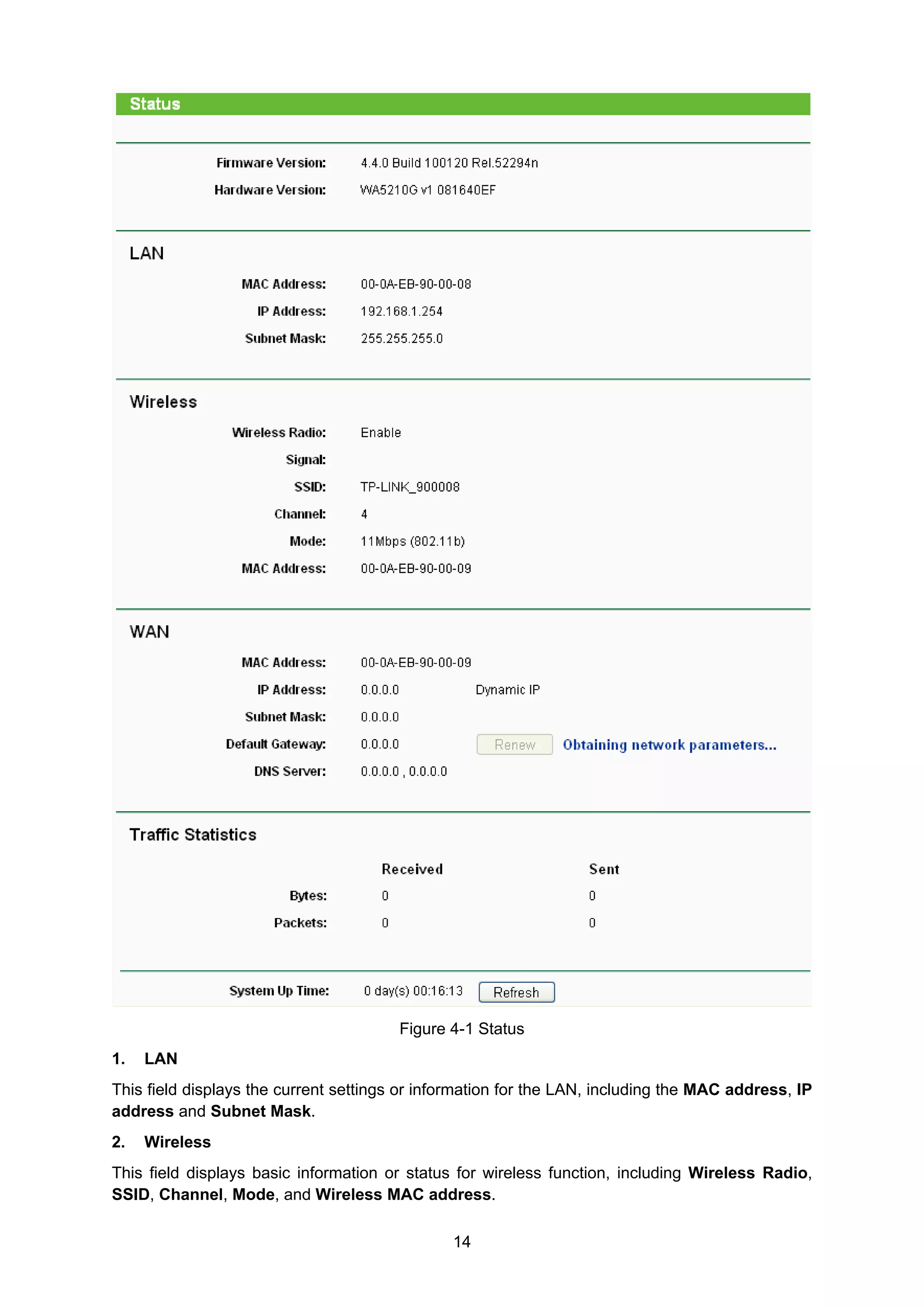


![[Alueseminaari] Antti Tuomainen - One Planet Living -konsepti Suomessa](https://cdn.slidesharecdn.com/ss_thumbnails/9-141009064712-conversion-gate01-thumbnail.jpg?width=640&height=640&fit=bounds)


