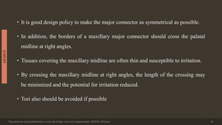
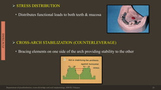
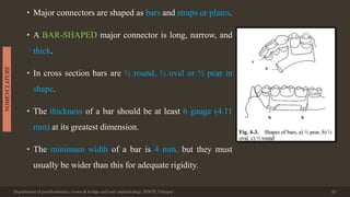
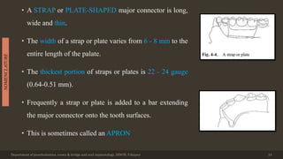
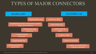
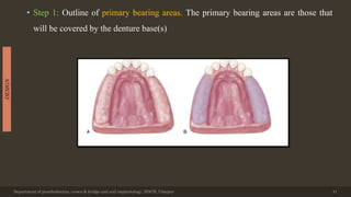
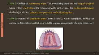
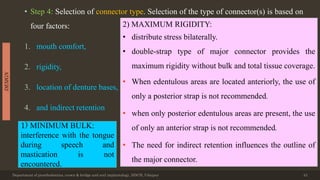
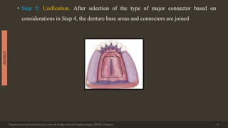
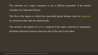
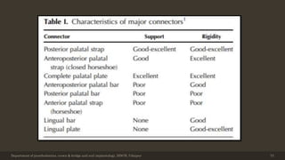
The document discusses major connectors for removable partial dentures. It defines major connectors as parts that join components on both sides of the dental arch, providing cross-arch stabilization. Major connectors must be rigid to distribute forces evenly without damaging tissues. They are named based on location and shape, with common types being palatal bars, straps, and plates in the maxilla and lingual bars in the mandible. The document outlines design considerations and characteristics of different major connector types.


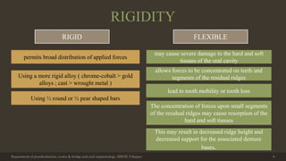


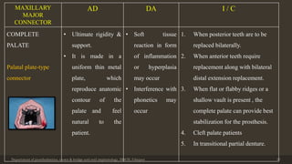


![Wada J, Hideshima M, Uchikura K, Shichiri Y, Inukai S, Matsuura H, Wakabayashi
N. Influence of the Covering Area of Major Connectors of Mandibular Dentures on
the Accuracy of Speech Production: A Pilot Study. Folia Phoniatrica et Logopaedica.
2020;72(6):419-28.
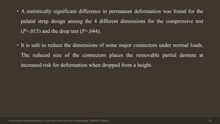
• Fifteen adults (12 men and 3 women aged 26–40 years) with healthy dentition were
recruited. Four target syllables were used for the assessments: [i], [ti], [çi], and [ki]. There
were four speaking conditions: without a connector (control), wearing lingual bar (5 mm
width), wearing lingual plates (12 mm width), and wearing connectors covering the
occlusal surface of lower dentition (16 mm width; CO). The accuracy of speech
production was evaluated by mean appearance ratio of correct labels (MARC) and
incorrect labels (MARIC) of the phonetic segments which were calculated with a speech
evaluation system (VoiceAnalyzer).
Department of prosthodontics, crown & bridge and oral implantology, DDCH, Udaipur 75](https://image.slidesharecdn.com/majorconnectorsp-220205182827/85/Major-connectors-75-320.jpg)
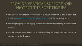
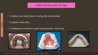
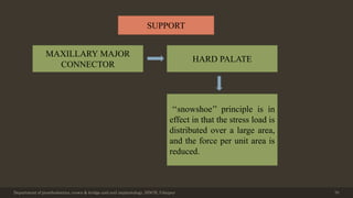
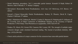
![• The MARC in the 3 target syllables [i], [ti], and [ki] significantly decreased with
CO. For the target syllable [ʃi], the MARICs of [ti], [i], and [çi] with CO were
significantly lower than that in the control. For the target syllable (ti], the MARIC
of [ki] with CO was significantly higher than that in the control. For the target
syllable [çi], the MARIC of [gi] with CO was significantly higher than that in the
control.
• RPDs with major connectors covering the lower dentition could disturb speech
production during the initial phase of RPD treatment. Prosthodontic treatment with
such RPD designs requires further consideration regarding the information given
to patients before starting the treatment.
Department of prosthodontics, crown & bridge and oral implantology, DDCH, Udaipur 76](https://image.slidesharecdn.com/majorconnectorsp-220205182827/85/Major-connectors-76-320.jpg)


![Prosthodontic management of endodontically treated teeth [autosaved]](https://cdn.slidesharecdn.com/ss_thumbnails/prosthodonticmanagementofendodonticallytreatedteethautosaved-210611115147-thumbnail.jpg?width=640&height=640&fit=bounds)


![Polymer [ बहुलक ] Chemistry Notes PDF - Irfanullah Mehar - JJ Sir Chemistry.pdf](https://cdn.slidesharecdn.com/ss_thumbnails/polymerchemistrynotespdf-irfanullahmehar-jjsirchemistry-260210172118-3f9b37f7-thumbnail.jpg?width=640&height=640&fit=bounds)


