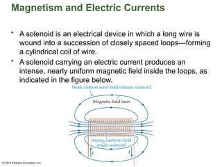
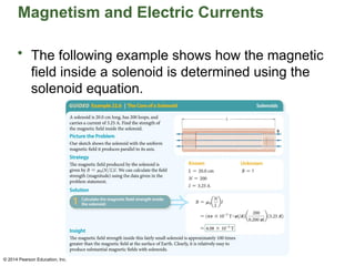
Chapter 22 Lecture
© 2014 Pearson Education, Inc.
Pearson Physics
Magnetism and
Magnetic Fields
Prepared by
Chris Chiaverina
© 2014 Pearson Education, Inc.
Chapter Contents
• Magnets and Magnetic Fields
• Magnetism and Electric Currents
• The Magnetic Force
© 2014 Pearson Education, Inc.
Magnets and Magnetic Fields
• The effects of magnetism have been known
since antiquity. For example, a piece of naturally
occurring iron-oxide mineral known as lodestone
can behave just like a manufactured magnet.
• Your first direct experience with magnetism was
probably a playful exploration of bar magnets
and their properties. From such experiences, you
know that the two ends of a magnet are different.
• Specifically, you learned that a bar magnet
attracts or repels another bar magnet depending
on which ends of the magnet are brought
together.
© 2014 Pearson Education, Inc.
Magnets and Magnetic Fields
• One end of a magnet is referred to as its north
pole and is labeled N. The other end of a
magnet is its south pole, which is labeled S.
• The poles of a bar magnet are defined by
suspending it from a string so that it is free to
rotate like a compass needle.
• The end of a freely rotating bar magnet that
points toward the north geographic pole of the
Earth is the north-seeking pole, or simply the
north pole.
• The opposite end of the magnet is the
south-seeking pole, or simply the south pole.
© 2014 Pearson Education, Inc.
Magnets and Magnetic Fields
• An interesting aspect of magnets is that they
always have two poles. You might think that if
you broke a magnet in two, each of the halves
would have just one pole. That's not what
happens. Instead, breaking a magnet in half
produces two new poles on either side of the
break, as is illustrated in the figure below.
© 2014 Pearson Education, Inc.
Magnets and Magnetic Fields
• This behavior is different from that of electricity, in that
the two types of charge (positive and negative) can exist
separately. Physicists continue to look for a single
magnetic pole, known as a magnetic monopole, but
none has been found.
• If two magnets are brought together in such a way that
their opposite poles approach each other, as in the figure
below, the force each experiences is attractive.
© 2014 Pearson Education, Inc.
Magnets and Magnetic Fields
• Like poles brought together, as shown below,
experience a repulsive force.
• Just as an electric charge creates an electric
field, so too does a magnet create a magnetic
field. A magnetic field is a vector force field that
surrounds any magnetic material.
© 2014 Pearson Education, Inc.
Magnets and Magnetic Fields
• In addition to exerting force, a magnetic field also
contains energy, just like an electric field. The greater the
energy, the more intense the field.
• A magnetic field, which is represented with the symbol B,
can be visualized using small iron filings sprinkled onto a
smooth surface. In figure (a) on the next slide, for
example, a sheet of glass is placed on top of a bar
magnet. When iron filings are sprinkled onto the glass
sheet, they align with the magnetic field in their vicinity.
The pattern they form gives a good idea of the overall
field produced by the magnet.
© 2014 Pearson Education, Inc.
Magnets and Magnetic Fields
• Similar effects are created by the magnet shown in the
figure below. Because of its shape, the magnet is
referred to as a horseshoe magnet.
© 2014 Pearson Education, Inc.
Magnets and Magnetic Fields
• Notice that the filings are bunched together near
the poles of the magnets in the previous figures.
This is where the magnet field is most intense.
This can be illustrated by drawing field lines that
are close together to one another near the poles
(see figure below).
© 2014 Pearson Education, Inc.
Magnets and Magnetic Fields
• The field weakens as you move away from the
magnet in any direction. This weakening is
indicated by a wider separation between field
lines.
© 2014 Pearson Education, Inc.
Magnets and Magnetic Fields
• In addition, the lines form closed loops that
leave the magnet at the north pole and enter
it at the south pole.
• As the previous figure indicates, the direction
of a magnetic field at a given location is
defined as the direction a compass needle
would point if placed at that location.
• Because opposites attract, the north pole of
a compass needle—the end with the
arrowhead—points toward the south pole of
the magnet.
© 2014 Pearson Education, Inc.
Magnets and Magnetic Fields
• Recall that that the direction in which a compass
points at any given location is the direction of the
magnetic field at that point. Since a compass
can point in one direction at a given point, there
must be only one direction for the magnetic field,
B. If field lines were to cross, there would be two
directions for B at the crossing point. As a result,
magnetic field lines can never cross.
© 2014 Pearson Education, Inc.
Magnets and Magnetic Fields
• The common household refrigerator magnet provides an
interesting example of a magnetic field.
• These magnets are composed of multiple narrow
magnet strips of opposite polarity, as indicated in the
figure below.
© 2014 Pearson Education, Inc.
Magnets and Magnetic Fields
• The net effect of these strips is a magnetic field
similar to the field that would be produced by a
large number of tiny horseshoe magnets placed
side by side.
© 2014 Pearson Education, Inc.
Magnets and Magnetic Fields
• Earth, like many planets, produces its own
magnetic field. In many respects, Earth's
magnetic field is like that of a giant bar magnet,
as illustrated in the figure below.
© 2014 Pearson Education, Inc.
Magnets and Magnetic Fields
• As the preceding figure indicates, there is a
magnetic pole near each geographic pole of the
Earth. In addition, the field lines are essentially
horizontal (parallel to the Earth's surface) near
the equator but enter or leave the Earth near the
poles.
• Because the north pole of a compass points
toward the north geographic pole of Earth, and
because opposites attract, we can conclude that
the north geographic pole of Earth is actually
near the south pole of the Earth's magnetic field.
This is shown in the figure on the previous slide.
© 2014 Pearson Education, Inc.
Magnets and Magnetic Fields
• The axis of the magnetic poles is not perfectly
aligned with the rotational axis of the Earth.
Instead, it is inclined at an angle that varies
slowly with time. Presently, the magnetic axis is
tilted away from the rotational axis by an angle
of about 11.5°.
• Scientist know that Earth's magnetic field has
reversed direction many times over the ages.
The last reversal occurred about 780,000 years
ago. There are signs that Earth may be
preparing for another such reversal.
© 2014 Pearson Education, Inc.
Magnets and Magnetic Fields
• As magnetic fields go, Earth's is relatively weak.
To make this quantitative, we note that magnetic
field strength is measured in terms of a unit
called the tesla (T). The tesla is named in
recognition of the pioneering electrical and
magnetic studies of the Croatian-born American
engineer Nikola Tesla (1856–1943).
• A magnetic field of 1 T is rather large. In
comparison, the magnetic field at the surface of
Earth is roughly 5.0 x 10⁻⁵
T.
• Another commonly used unit for magnetism is
the gauss (G), which is defined as 1 G = 10−4
T.
© 2014 Pearson Education, Inc.
Magnets and Magnetic Fields
• The gauss is not an SI unit. Even so, it finds wide
usage because of its convenient magnitude. In
terms of the gauss, Earth's magnetic field at its
surface is approximately 0.5 G.
• The magnitudes of some typical magnetic fields
are given in the table below.
© 2014 Pearson Education, Inc.
Magnets and Magnetic Fields
• As was mentioned previously, Earth's magnetic field
reverses direction over geological time periods. These
reversals have left a permanent record in the rocks of
the ocean floors.
• The figure below shows that molten rock is being
extruded from a mid-ocean ridge.
© 2014 Pearson Education, Inc.
Magnets and Magnetic Fields
• The extruded rock has no magnetization
because of its high temperature. When the rock
cools, however, it becomes magnetized in the
direction of Earth's magnetic field. In effect, the
direction of Earth's magnetic field becomes
"frozen" in the solidified rock.
• As the seafloor spreads, and more rock is
formed along the mid-ocean ridge, a continuous
record of Earth's magnetic field is formed. If the
Earth's field reverses at some point in time, the
field in the solidified rock will record the fact.
© 2014 Pearson Education, Inc.
Magnets and Magnetic Fields
• At the microscopic level, the magnetic field of
a magnet is due to the magnetic fields
produced by electrons in its atoms. Each
electron acts like a small bar magnet.
• In some materials the magnetic fields of the
electrons cancel, leaving zero net magnetic
field.
• In other materials—like iron, nickel, and
cobalt—the magnetic fields of the electrons
don't cancel, and the electrons in neighboring
atoms tend to align with one another,
producing a strong magnetic field.
© 2014 Pearson Education, Inc.
Magnets and Magnetic Fields
• The magnetic field of any magnetic material is
broken up into regions in which the field points in
different directions, as is indicated in the figure
below.
• A region within a magnetic material where the
electrons are aligned in the same direction is
referred to as a magnetic domain.
© 2014 Pearson Education, Inc.
Magnets and Magnetic Fields
• Each domain has a strong magnetic field in a
given direction. Different domains are oriented
differently, however, so that the net effect may
be small. The typical size of these domains is on
the order of 10−4
cm to 10−1
cm.
• When an external magnetic field is applied to
such a material, the magnetic domains that are
pointing in the direction of the applied field tend
to grow in size at the expense of the domains
with different orientations.
© 2014 Pearson Education, Inc.
Magnets and Magnetic Fields
• This is illustrated in the figure below. The result
is a net magnetization of the material—it
becomes a permanent magnet.
© 2014 Pearson Education, Inc.
Magnets and Magnetic Fields
• Many small animals are known to have small
magnetic crystals (magnetite) in their bodies. For
example, some species of bacteria use
magnetite crystals to help orient themselves with
respect to Earth's magnetic field.
• Magnetite has also been found in the brains of
bees and pigeons, where it is thought to play a
role in navigation. It is even found in human
brains, though its possible function there is
unclear.
© 2014 Pearson Education, Inc.
Magnetism and Electric Currents
• The connection between electricity and
magnetism was discovered accidentally by the
Danish scientist Hans Christian Oersted
(1777–1851) in 1820.
• Oersted was giving a science lecture when he
closed a switch and allowed a current to flow
through a wire. He noticed that a nearby
compass needle rotated rapidly when the
switch was closed.
• With that simple observation, Oersted
discovered that electric currents can create
magnetic fields.
© 2014 Pearson Education, Inc.
Magnetism and Electric Currents
• To visualize the magnetic field produced by a wire,
consider a long, straight wire that carries a current, I.
• Shaking iron filings onto a sheet of paper that is pierced
by the wire results in a circular pattern of filings centered
on the wire (see figure (a) below). Clearly, the magnetic
field "circulates" around the wire.
© 2014 Pearson Education, Inc.
Magnetism and Electric Currents
• We can gain additional information about the
magnetic field by placing a group of small
compasses about the wire, as in figure (b) below.
• In addition to confirming the circular shape of the
field lines, the compass needles show the field's
direction.
© 2014 Pearson Education, Inc.
Magnetism and Electric Currents
• To understand this direction, we use the
magnetic field right-hand rule (RHR):
• This rule is illustrated by the compass needles in
the figure on the next slide.
© 2014 Pearson Education, Inc.
Magnetism and Electric Currents
• As the figure indicates, to find the direction of
the field, point the thumb of the right hand in the
direction of the current, I. The fingers then curl in
the direction of the magnetic field, B.
© 2014 Pearson Education, Inc.
Magnetism and Electric Currents
• In some cases a magnetic field will point into or
out of the page. This can be difficult to draw.
Therefore, we establish the convention that the
symbol indicates that the magnetic field
⊗
points into the page.
• The way to remember this is to think of a
magnetic field vector as an arrow. At the end of
the arrow are crossed feathers. Therefore, if you
view a vector from behind, it looks like an X.
© 2014 Pearson Education, Inc.
Magnetism and Electric Currents
• Similarly, if the arrow points out of the page, all you will
see is the point at its tip. Thus, we represent a magnetic
field vector pointing out of the page with the symbol ,
⊙
where the dot represents the tip of the arrow.
• These convections are applied in the following example.
© 2014 Pearson Education, Inc.
Magnetism and Electric Currents
• Experiments show that the magnetic field
produced by a current-carrying wire doubles if the
current, I, doubles. In addition, the field doubles if
the radial distance from the wire, r, is halved.
• These observations are summarized in one
statement: The magnetic field produced by a
current in a wire is proportional to the current and
inversely proportional to the radial distance from
the wire.
© 2014 Pearson Education, Inc.
Magnetism and Electric Currents
• The magnetic field for a long, straight wire is
given by the following equation:
• In this equation, µ0, is a constant called the
permeability of free space. Its value is
µ0 = 4π x 10−7
T·m/A
© 2014 Pearson Education, Inc.
Magnetism and Electric Currents
• The following example shows how to use the
magnetic field equation.
© 2014 Pearson Education, Inc.
Magnetism and Electric Currents
• The following example illustrates how the total
magnetic field is found when two current-carrying
wires contribute to the field.
© 2014 Pearson Education, Inc.
Magnetism and Electric Currents
• You've seen that a long, straight wire carrying an electric
current produces a magnetic field. What happens if a
straight wire is wrapped into a circular loop instead?
• Figure (a) below shows a wire loop connected to a
battery producing a current in the direction indicated.
© 2014 Pearson Education, Inc.
Magnetism and Electric Currents
• Using the magnetic field RHR, as shown in the
figure, we see that the magnetic field points from
left to right as it passes through the loop.
• Notice also that the field lines are bunched
together within the loop, indicating that the field is
intense there. The field lines are more widely
spaced outside the loop, where the field is weaker.
• The most interesting aspect of the field produced
by the current-carrying loop is its close
resemblance to the field of a bar magnet, as is
illustrated in figure (b) on the next slide.
© 2014 Pearson Education, Inc.
Magnetism and Electric Currents
• Notice that one side of the loop behaves like a
north magnetic pole (with field lines exiting) and
the other side like a south magnetic pole (with
field lines entering).
© 2014 Pearson Education, Inc.
Magnetism and Electric Currents
• When two loops with identical currents are
placed next to one another, the force between
loops will be similar to the force between two bar
magnets pointing in the same direction (see
figure below).
© 2014 Pearson Education, Inc.
Magnetism and Electric Currents
• As you can see, the ghosted bar magnets would attract
one another, since their opposite poles are near one
another.
• Therefore, wires with currents in the same direction
experience an attractive force.
• As figure (b) below indicates, wires with currents in
opposite directions experience a repulsive force.
© 2014 Pearson Education, Inc.
Magnetism and Electric Currents
• A solenoid is an electrical device in which a long wire is
wound into a succession of closely spaced loops—forming
a cylindrical coil of wire.
• A solenoid carrying an electric current produces an
intense, nearly uniform magnetic field inside the loops, as
indicated in the figure below.
© 2014 Pearson Education, Inc.
Magnetism and Electric Currents
• For this reason, solenoids are commonly
referred to as electromagnets.
• Notice that each loop of a solenoid carries a
current in the same direction. It follows that the
magnetic field between loops is attractive and
serves to hold them tightly together.
• The magnetic field lines in the previous figure
are tightly packed inside the solenoid but are
widely spaced outside. In the case of a very
long, tightly packed solenoid, the magnetic field
is intense and uniform inside the solenoid.
© 2014 Pearson Education, Inc.
Magnetism and Electric Currents
• If a solenoid has N loops and length L, the
magnetic field inside the solenoid is given by the
following equation:
• Notice that the result is independent of the
cross-sectional area of the solenoid and that the
field depends directly on the number of loops
per unit length and on the current.
© 2014 Pearson Education, Inc.
Magnetism and Electric Currents
• When used as an electromagnet, a solenoid
has many useful properties.
– A solenoid produces a strong magnetic field
that can be turned on or off at the flip of
switch—unlike the field of a permanent
magnet.
– The magnetic field of a solenoid can be
intensified by filling the core of the solenoid
with an iron bar. In such a case, the magnetic
field of the solenoid magnetizes the iron bar,
and its field adds to that of the solenoid.
© 2014 Pearson Education, Inc.
Magnetism and Electric Currents
• The following example shows how the magnetic
field inside a solenoid is determined using the
solenoid equation.
© 2014 Pearson Education, Inc.
The Magnetic Force
• A magnetic field exerts a force on a moving charge. Both
the magnitude and the direction of this force have some
rather interesting characteristics.
• Consider a magnetic field, B, that points from left to right,
as indicated in the figure below.
• Suppose an object with a charge q moves through the
region with velocity v, and the angle between v and B is θ.
© 2014 Pearson Education, Inc.
The Magnetic Force
• Experiment shows that the magnitude of the
force F experienced by this object is given by
the following equation:
© 2014 Pearson Education, Inc.
The Magnetic Force
• Notice that the equation uses the magnitude of
the charge, |q|, because we are calculating the
magnitude of the force.
• The equation also shows that the magnitude of
the force depends on several different factors.
Two of these factors are the same as the electric
force.
– The magnetic force depends on the charge of
the object, q.
– The magnetic force depends on the
magnitude of the field, in this case, the
magnetic field, B.
© 2014 Pearson Education, Inc.
The Magnetic Force
• However, the magnetic force also depends on
two factors that do not affect the strength of the
electric force:
– The magnetic force depends on the speed of
the object, v. An object at rest experiences no
force.
– The magnetic force depends on the angle θ
between the velocity vector and the magnetic
field vector.
© 2014 Pearson Education, Inc.
The Magnetic Force
• It is important to note that an object must have a
charge and must be moving if the magnetic field
is to exert a force on it. Even then the force
vanishes if the object moves in the direction of
the field (that is, if θ = 0) or in the direction
opposite to the field (θ = 180°).
• Maximum magnetic force is exerted when a
charged object moves at right angles to the
magnetic field, so θ = 90° and sinθ = 1.
© 2014 Pearson Education, Inc.
The Magnetic Force
• The following
example illustrates
how the force on a
charge moving
through a magnetic
field can be
calculated.
© 2014 Pearson Education, Inc.
The Magnetic Force
• We now consider the direction of the magnetic force.
Surprisingly, the force does not point in the direction of the
magnetic field, B, or the velocity, v. The magnetic force, F,
points in a direction that is perpendicular to both B and v.
• As an example, consider the vectors B and v in figure (a)
below. The force on a positive charge, F, is perpendicular
to the plane containing B and v. Thus, the force is
perpendicular to both B and v.
© 2014 Pearson Education, Inc.
The Magnetic Force
• The way the precise direction of F is determined
is with another right-hand rule (RHR). To be
specific, the direction of F is found using the
magnetic force right-hand rule:
© 2014 Pearson Education, Inc.
The Magnetic Force
• This rule is applied in figures (b) and (c) below.
Notice that F does indeed point upward for a
positive charge.
© 2014 Pearson Education, Inc.
The Magnetic Force
• As an additional example, the figure below shows a
uniform magnetic field, B, that points into the page. An
object with a positive charge moves to the right. Using
the magnetic force RHR, we see that the force exerted
on this object is upward, as indicated. If the charge is
negative, the direction of F is reversed, as shown.
© 2014 Pearson Education, Inc.
The Magnetic Force
• An application of magnetic force RHR is
illustrated in the following example.
© 2014 Pearson Education, Inc.
The Magnetic Force
• The deflection of moving charges by a magnetic field is
illustrated in the figure below.
• The image on the TV screen is produced by a beam of
electrons that "paints" the picture on the screen by
illuminating the appropriate pixels. When a magnet is held
near the screen, the electrons in the beam are deflected
by the magnetic force, resulting in a scrambled picture.
© 2014 Pearson Education, Inc.
The Magnetic Force
• On a large scale, the northern lights—or aurora
borealis—are produced in a similar way. Positive
and negative particles, ripped apart from atoms
on the Sun by extremely high temperatures,
form a gas-like collection of ions referred to as a
plasma.
• Plasmas can be thought of the fourth state of
matter. Though a plasma is similar to a gas, the
fact that it consists of electrically charged
particles means that electric and magnetic fields
have a great influence on its behavior.
© 2014 Pearson Education, Inc.
The Magnetic Force
• For example, figure (a) below shows streams of
plasma shooting up from a storm on the surface
of the Sun. The plasma follows arching paths
that trace out the magnetic lines of the Sun.
© 2014 Pearson Education, Inc.
The Magnetic Force
• Plasma shot into space from the Sun in an event known
as a coronal mass ejection forms what is known as a
solar wind. When the solar wind encounters Earth's
magnetic field, the charged particles are deflected by the
magnetic force. As a result, these particles concentrate
where the field is most intense—near the poles of Earth
(see figure (b) below).
© 2014 Pearson Education, Inc.
The Magnetic Force
• The particles excite atoms in the atmosphere,
causing them to glow and thus producing the
northern lights, shown in figure (c) below, as well
as their southern cousins, the aurora australis.
© 2014 Pearson Education, Inc.
The Magnetic Force
• If the velocity of a charged object is perpendicular
to a magnetic field, the result is circular motion of
the object.
• In the figure below, an object of mass m, charge
+q, and speed v moves in a region with constant
magnetic field, B, pointing out of the paper.
© 2014 Pearson Education, Inc.
The Magnetic Force
• Since v is at right angle to B, the magnitude of
the magnetic force is F = |q|vb sin90° = |q|vB.
The force has the same magnitude at each of
the points 1,2,3 and 4.
• The previous figure also shows that the
magnetic force is at right angles to the velocity
(and thus always points toward the center of the
circle) at every point on the object's path. This is
exactly the condition required for circular motion.
• This center-seeking, or centripetal, force
produces an acceleration toward the center of
the circle referred to as centripetal acceleration.
© 2014 Pearson Education, Inc.
The Magnetic Force
• The centripetal acceleration of an object moving
with a speed v in a circle of radius r is
acp = v2
/r
• Therefore, setting macp equal to the magnitude
of the magnetic force, |q|vB, yields the following
condition:
mv2
/r = |q|vB
• Simplifying yields
mv/r = |q|B
• Solving for the radius r,
r = mv/|q|B
© 2014 Pearson Education, Inc.
The Magnetic Force
• Therefore, the faster and the more massive the object,
the larger the circle. Conversely, the stronger the
magnetic field and the greater the charge, the smaller
the circle.
• The following example shows how the speed of a
charged object, in this case an electron, can be
determined knowing m, |q|, r, and B.
© 2014 Pearson Education, Inc.
The Magnetic Force
• A mass spectrometer is a device that makes use of
circular motion in a magnetic field to separate isotopes
(atoms of the same element that have different masses).
• In a mass spectrometer, a beam of charged particles
enters a region with a magnetic field perpendicular to the
velocity (see figure below).
© 2014 Pearson Education, Inc.
The Magnetic Force
• The particles then follow a circular orbit of radius
r = mv/|q|B. Particles of different mass follow
different paths, allowing them to be separated
from one another.
• The example on the next slide illustrates the
operation of a mass spectrometer.
© 2014 Pearson Education, Inc.
The Magnetic Force
© 2014 Pearson Education, Inc.
The Magnetic Force
• A charged object experiences a force when it moves
across magnetic field lines. This is true whether it travels
in a vacuum or inside a current-carrying wire.
• Thus, a wire carrying a current in a magnetic field
experiences a magnetic force that is simply the sum of
all the magnetic forces experienced by the individual
charges moving within it.
• To see how the force on a current-carrying wire is related
to the forces on the individual charges, consider a
straight wire segment of length L with a current I flowing
left to right, as shown in the figure on the next slide.
© 2014 Pearson Education, Inc.
The Magnetic Force
• As the figure indicates, there is also a magnetic
field B present.
• The conducting charges move through the wire
with an average speed given by
v = L/Δt
© 2014 Pearson Education, Inc.
The Magnetic Force
• Here, Δt is the time required for the charges to
move from one end of the wire to the other. The
amount of charge that flows through the wire in
this time is
q = IΔt
• Therefore, the force exerted on the wire is
F = qvB sinθ = (IΔt)(L/Δt)B sinθ
© 2014 Pearson Education, Inc.
The Magnetic Force
• Cancelling the time Δt, we find that the force on
a wire of length L with a current I at angle θ to a
magnetic field B is given by the following
equation:
© 2014 Pearson Education, Inc.
The Magnetic Force
• The direction of the force on a current-carrying
wire is given by the magnetic force RHR; the
only difference is that you start by pointing your
right hand in the direction of the current, I.
• In the case illustrated in the figure below, the
force points out of the page.
© 2014 Pearson Education, Inc.
The Magnetic Force
• The following
example illustrates
how the direction
and magnitude of
the force on a
current-carrying wire
in a magnetic field
are determined.
© 2014 Pearson Education, Inc.
The Magnetic Force
• The fact that a current-carrying wire experiences
a force when placed in a magnetic field is one of
the fundamental discoveries that makes modern
applications of electric power possible. In most
of these applications, including electric motors
and generators, the wire is shaped into a
current-carrying loop.
• We will now examine what happens when a
simple current-carrying loop is placed in a
magnetic field.
© 2014 Pearson Education, Inc.
The Magnetic Force
• In the figure below, a rectangular loop of height h and
width w carrying a current I is placed in a region of space
with a uniform magnetic field B that is parallel to the
plane of the loop.
• The horizontal segments of the loop experience zero
force because they are parallel to the field.
© 2014 Pearson Education, Inc.
The Magnetic Force
• The vertical segments are perpendicular to the
field and therefore experience forces of
magnitude F = IhB. One of these forces is
directed into the page (left side); the other points
out of the page (right side). These forces tend to
rotate the loop—that is, they cause a torque.
© 2014 Pearson Education, Inc.
The Magnetic Force
• The torque exerted by a magnetic field finds a
number of useful applications. For example, if a
needle is connected to a coil, as in the figure
below, it can be used as part of a meter known
as a galvanometer, which is a device used to
measure current in a circuit.
© 2014 Pearson Education, Inc.
The Magnetic Force
• As a current passes through a galvanometer's
coil, a torque acts on it, causing it to rotate. The
spring ensures that the angle of rotation is
proportional to the current in the coil.
• Of even greater importance is the fact that
magnetic torque can be used to power a motor.
• Electric current passing through the coils of a
motor causes a torque that rotates the axel of
the motor.
• Electric motors are used in everything from
electric razors to hybrid cars.

Magnetism and Magnetic Fields PowerPoint

  • 1.
    Chapter 22 Lecture ©2014 Pearson Education, Inc. Pearson Physics Magnetism and Magnetic Fields Prepared by Chris Chiaverina
  • 2.
    © 2014 PearsonEducation, Inc. Chapter Contents • Magnets and Magnetic Fields • Magnetism and Electric Currents • The Magnetic Force
  • 3.
    © 2014 PearsonEducation, Inc. Magnets and Magnetic Fields • The effects of magnetism have been known since antiquity. For example, a piece of naturally occurring iron-oxide mineral known as lodestone can behave just like a manufactured magnet. • Your first direct experience with magnetism was probably a playful exploration of bar magnets and their properties. From such experiences, you know that the two ends of a magnet are different. • Specifically, you learned that a bar magnet attracts or repels another bar magnet depending on which ends of the magnet are brought together.
  • 4.
    © 2014 PearsonEducation, Inc. Magnets and Magnetic Fields • One end of a magnet is referred to as its north pole and is labeled N. The other end of a magnet is its south pole, which is labeled S. • The poles of a bar magnet are defined by suspending it from a string so that it is free to rotate like a compass needle. • The end of a freely rotating bar magnet that points toward the north geographic pole of the Earth is the north-seeking pole, or simply the north pole. • The opposite end of the magnet is the south-seeking pole, or simply the south pole.
  • 5.
    © 2014 PearsonEducation, Inc. Magnets and Magnetic Fields • An interesting aspect of magnets is that they always have two poles. You might think that if you broke a magnet in two, each of the halves would have just one pole. That's not what happens. Instead, breaking a magnet in half produces two new poles on either side of the break, as is illustrated in the figure below.
  • 6.
    © 2014 PearsonEducation, Inc. Magnets and Magnetic Fields • This behavior is different from that of electricity, in that the two types of charge (positive and negative) can exist separately. Physicists continue to look for a single magnetic pole, known as a magnetic monopole, but none has been found. • If two magnets are brought together in such a way that their opposite poles approach each other, as in the figure below, the force each experiences is attractive.
  • 7.
    © 2014 PearsonEducation, Inc. Magnets and Magnetic Fields • Like poles brought together, as shown below, experience a repulsive force. • Just as an electric charge creates an electric field, so too does a magnet create a magnetic field. A magnetic field is a vector force field that surrounds any magnetic material.
  • 8.
    © 2014 PearsonEducation, Inc. Magnets and Magnetic Fields • In addition to exerting force, a magnetic field also contains energy, just like an electric field. The greater the energy, the more intense the field. • A magnetic field, which is represented with the symbol B, can be visualized using small iron filings sprinkled onto a smooth surface. In figure (a) on the next slide, for example, a sheet of glass is placed on top of a bar magnet. When iron filings are sprinkled onto the glass sheet, they align with the magnetic field in their vicinity. The pattern they form gives a good idea of the overall field produced by the magnet.
  • 9.
    © 2014 PearsonEducation, Inc. Magnets and Magnetic Fields • Similar effects are created by the magnet shown in the figure below. Because of its shape, the magnet is referred to as a horseshoe magnet.
  • 10.
    © 2014 PearsonEducation, Inc. Magnets and Magnetic Fields • Notice that the filings are bunched together near the poles of the magnets in the previous figures. This is where the magnet field is most intense. This can be illustrated by drawing field lines that are close together to one another near the poles (see figure below).
  • 11.
    © 2014 PearsonEducation, Inc. Magnets and Magnetic Fields • The field weakens as you move away from the magnet in any direction. This weakening is indicated by a wider separation between field lines.
  • 12.
    © 2014 PearsonEducation, Inc. Magnets and Magnetic Fields • In addition, the lines form closed loops that leave the magnet at the north pole and enter it at the south pole. • As the previous figure indicates, the direction of a magnetic field at a given location is defined as the direction a compass needle would point if placed at that location. • Because opposites attract, the north pole of a compass needle—the end with the arrowhead—points toward the south pole of the magnet.
  • 13.
    © 2014 PearsonEducation, Inc. Magnets and Magnetic Fields • Recall that that the direction in which a compass points at any given location is the direction of the magnetic field at that point. Since a compass can point in one direction at a given point, there must be only one direction for the magnetic field, B. If field lines were to cross, there would be two directions for B at the crossing point. As a result, magnetic field lines can never cross.
  • 14.
    © 2014 PearsonEducation, Inc. Magnets and Magnetic Fields • The common household refrigerator magnet provides an interesting example of a magnetic field. • These magnets are composed of multiple narrow magnet strips of opposite polarity, as indicated in the figure below.
  • 15.
    © 2014 PearsonEducation, Inc. Magnets and Magnetic Fields • The net effect of these strips is a magnetic field similar to the field that would be produced by a large number of tiny horseshoe magnets placed side by side.
  • 16.
    © 2014 PearsonEducation, Inc. Magnets and Magnetic Fields • Earth, like many planets, produces its own magnetic field. In many respects, Earth's magnetic field is like that of a giant bar magnet, as illustrated in the figure below.
  • 17.
    © 2014 PearsonEducation, Inc. Magnets and Magnetic Fields • As the preceding figure indicates, there is a magnetic pole near each geographic pole of the Earth. In addition, the field lines are essentially horizontal (parallel to the Earth's surface) near the equator but enter or leave the Earth near the poles. • Because the north pole of a compass points toward the north geographic pole of Earth, and because opposites attract, we can conclude that the north geographic pole of Earth is actually near the south pole of the Earth's magnetic field. This is shown in the figure on the previous slide.
  • 18.
    © 2014 PearsonEducation, Inc. Magnets and Magnetic Fields • The axis of the magnetic poles is not perfectly aligned with the rotational axis of the Earth. Instead, it is inclined at an angle that varies slowly with time. Presently, the magnetic axis is tilted away from the rotational axis by an angle of about 11.5°. • Scientist know that Earth's magnetic field has reversed direction many times over the ages. The last reversal occurred about 780,000 years ago. There are signs that Earth may be preparing for another such reversal.
  • 19.
    © 2014 PearsonEducation, Inc. Magnets and Magnetic Fields • As magnetic fields go, Earth's is relatively weak. To make this quantitative, we note that magnetic field strength is measured in terms of a unit called the tesla (T). The tesla is named in recognition of the pioneering electrical and magnetic studies of the Croatian-born American engineer Nikola Tesla (1856–1943). • A magnetic field of 1 T is rather large. In comparison, the magnetic field at the surface of Earth is roughly 5.0 x 10⁻⁵ T. • Another commonly used unit for magnetism is the gauss (G), which is defined as 1 G = 10−4 T.
  • 20.
    © 2014 PearsonEducation, Inc. Magnets and Magnetic Fields • The gauss is not an SI unit. Even so, it finds wide usage because of its convenient magnitude. In terms of the gauss, Earth's magnetic field at its surface is approximately 0.5 G. • The magnitudes of some typical magnetic fields are given in the table below.
  • 21.
    © 2014 PearsonEducation, Inc. Magnets and Magnetic Fields • As was mentioned previously, Earth's magnetic field reverses direction over geological time periods. These reversals have left a permanent record in the rocks of the ocean floors. • The figure below shows that molten rock is being extruded from a mid-ocean ridge.
  • 22.
    © 2014 PearsonEducation, Inc. Magnets and Magnetic Fields • The extruded rock has no magnetization because of its high temperature. When the rock cools, however, it becomes magnetized in the direction of Earth's magnetic field. In effect, the direction of Earth's magnetic field becomes "frozen" in the solidified rock. • As the seafloor spreads, and more rock is formed along the mid-ocean ridge, a continuous record of Earth's magnetic field is formed. If the Earth's field reverses at some point in time, the field in the solidified rock will record the fact.
  • 23.
    © 2014 PearsonEducation, Inc. Magnets and Magnetic Fields • At the microscopic level, the magnetic field of a magnet is due to the magnetic fields produced by electrons in its atoms. Each electron acts like a small bar magnet. • In some materials the magnetic fields of the electrons cancel, leaving zero net magnetic field. • In other materials—like iron, nickel, and cobalt—the magnetic fields of the electrons don't cancel, and the electrons in neighboring atoms tend to align with one another, producing a strong magnetic field.
  • 24.
    © 2014 PearsonEducation, Inc. Magnets and Magnetic Fields • The magnetic field of any magnetic material is broken up into regions in which the field points in different directions, as is indicated in the figure below. • A region within a magnetic material where the electrons are aligned in the same direction is referred to as a magnetic domain.
  • 25.
    © 2014 PearsonEducation, Inc. Magnets and Magnetic Fields • Each domain has a strong magnetic field in a given direction. Different domains are oriented differently, however, so that the net effect may be small. The typical size of these domains is on the order of 10−4 cm to 10−1 cm. • When an external magnetic field is applied to such a material, the magnetic domains that are pointing in the direction of the applied field tend to grow in size at the expense of the domains with different orientations.
  • 26.
    © 2014 PearsonEducation, Inc. Magnets and Magnetic Fields • This is illustrated in the figure below. The result is a net magnetization of the material—it becomes a permanent magnet.
  • 27.
    © 2014 PearsonEducation, Inc. Magnets and Magnetic Fields • Many small animals are known to have small magnetic crystals (magnetite) in their bodies. For example, some species of bacteria use magnetite crystals to help orient themselves with respect to Earth's magnetic field. • Magnetite has also been found in the brains of bees and pigeons, where it is thought to play a role in navigation. It is even found in human brains, though its possible function there is unclear.
  • 28.
    © 2014 PearsonEducation, Inc. Magnetism and Electric Currents • The connection between electricity and magnetism was discovered accidentally by the Danish scientist Hans Christian Oersted (1777–1851) in 1820. • Oersted was giving a science lecture when he closed a switch and allowed a current to flow through a wire. He noticed that a nearby compass needle rotated rapidly when the switch was closed. • With that simple observation, Oersted discovered that electric currents can create magnetic fields.
  • 29.
    © 2014 PearsonEducation, Inc. Magnetism and Electric Currents • To visualize the magnetic field produced by a wire, consider a long, straight wire that carries a current, I. • Shaking iron filings onto a sheet of paper that is pierced by the wire results in a circular pattern of filings centered on the wire (see figure (a) below). Clearly, the magnetic field "circulates" around the wire.
  • 30.
    © 2014 PearsonEducation, Inc. Magnetism and Electric Currents • We can gain additional information about the magnetic field by placing a group of small compasses about the wire, as in figure (b) below. • In addition to confirming the circular shape of the field lines, the compass needles show the field's direction.
  • 31.
    © 2014 PearsonEducation, Inc. Magnetism and Electric Currents • To understand this direction, we use the magnetic field right-hand rule (RHR): • This rule is illustrated by the compass needles in the figure on the next slide.
  • 32.
    © 2014 PearsonEducation, Inc. Magnetism and Electric Currents • As the figure indicates, to find the direction of the field, point the thumb of the right hand in the direction of the current, I. The fingers then curl in the direction of the magnetic field, B.
  • 33.
    © 2014 PearsonEducation, Inc. Magnetism and Electric Currents • In some cases a magnetic field will point into or out of the page. This can be difficult to draw. Therefore, we establish the convention that the symbol indicates that the magnetic field ⊗ points into the page. • The way to remember this is to think of a magnetic field vector as an arrow. At the end of the arrow are crossed feathers. Therefore, if you view a vector from behind, it looks like an X.
  • 34.
    © 2014 PearsonEducation, Inc. Magnetism and Electric Currents • Similarly, if the arrow points out of the page, all you will see is the point at its tip. Thus, we represent a magnetic field vector pointing out of the page with the symbol , ⊙ where the dot represents the tip of the arrow. • These convections are applied in the following example.
  • 35.
    © 2014 PearsonEducation, Inc. Magnetism and Electric Currents • Experiments show that the magnetic field produced by a current-carrying wire doubles if the current, I, doubles. In addition, the field doubles if the radial distance from the wire, r, is halved. • These observations are summarized in one statement: The magnetic field produced by a current in a wire is proportional to the current and inversely proportional to the radial distance from the wire.
  • 36.
    © 2014 PearsonEducation, Inc. Magnetism and Electric Currents • The magnetic field for a long, straight wire is given by the following equation: • In this equation, µ0, is a constant called the permeability of free space. Its value is µ0 = 4π x 10−7 T·m/A
  • 37.
    © 2014 PearsonEducation, Inc. Magnetism and Electric Currents • The following example shows how to use the magnetic field equation.
  • 38.
    © 2014 PearsonEducation, Inc. Magnetism and Electric Currents • The following example illustrates how the total magnetic field is found when two current-carrying wires contribute to the field.
  • 39.
    © 2014 PearsonEducation, Inc. Magnetism and Electric Currents • You've seen that a long, straight wire carrying an electric current produces a magnetic field. What happens if a straight wire is wrapped into a circular loop instead? • Figure (a) below shows a wire loop connected to a battery producing a current in the direction indicated.
  • 40.
    © 2014 PearsonEducation, Inc. Magnetism and Electric Currents • Using the magnetic field RHR, as shown in the figure, we see that the magnetic field points from left to right as it passes through the loop. • Notice also that the field lines are bunched together within the loop, indicating that the field is intense there. The field lines are more widely spaced outside the loop, where the field is weaker. • The most interesting aspect of the field produced by the current-carrying loop is its close resemblance to the field of a bar magnet, as is illustrated in figure (b) on the next slide.
  • 41.
    © 2014 PearsonEducation, Inc. Magnetism and Electric Currents • Notice that one side of the loop behaves like a north magnetic pole (with field lines exiting) and the other side like a south magnetic pole (with field lines entering).
  • 42.
    © 2014 PearsonEducation, Inc. Magnetism and Electric Currents • When two loops with identical currents are placed next to one another, the force between loops will be similar to the force between two bar magnets pointing in the same direction (see figure below).
  • 43.
    © 2014 PearsonEducation, Inc. Magnetism and Electric Currents • As you can see, the ghosted bar magnets would attract one another, since their opposite poles are near one another. • Therefore, wires with currents in the same direction experience an attractive force. • As figure (b) below indicates, wires with currents in opposite directions experience a repulsive force.
  • 44.
    © 2014 PearsonEducation, Inc. Magnetism and Electric Currents • A solenoid is an electrical device in which a long wire is wound into a succession of closely spaced loops—forming a cylindrical coil of wire. • A solenoid carrying an electric current produces an intense, nearly uniform magnetic field inside the loops, as indicated in the figure below.
  • 45.
    © 2014 PearsonEducation, Inc. Magnetism and Electric Currents • For this reason, solenoids are commonly referred to as electromagnets. • Notice that each loop of a solenoid carries a current in the same direction. It follows that the magnetic field between loops is attractive and serves to hold them tightly together. • The magnetic field lines in the previous figure are tightly packed inside the solenoid but are widely spaced outside. In the case of a very long, tightly packed solenoid, the magnetic field is intense and uniform inside the solenoid.
  • 46.
    © 2014 PearsonEducation, Inc. Magnetism and Electric Currents • If a solenoid has N loops and length L, the magnetic field inside the solenoid is given by the following equation: • Notice that the result is independent of the cross-sectional area of the solenoid and that the field depends directly on the number of loops per unit length and on the current.
  • 47.
    © 2014 PearsonEducation, Inc. Magnetism and Electric Currents • When used as an electromagnet, a solenoid has many useful properties. – A solenoid produces a strong magnetic field that can be turned on or off at the flip of switch—unlike the field of a permanent magnet. – The magnetic field of a solenoid can be intensified by filling the core of the solenoid with an iron bar. In such a case, the magnetic field of the solenoid magnetizes the iron bar, and its field adds to that of the solenoid.
  • 48.
    © 2014 PearsonEducation, Inc. Magnetism and Electric Currents • The following example shows how the magnetic field inside a solenoid is determined using the solenoid equation.
  • 49.
    © 2014 PearsonEducation, Inc. The Magnetic Force • A magnetic field exerts a force on a moving charge. Both the magnitude and the direction of this force have some rather interesting characteristics. • Consider a magnetic field, B, that points from left to right, as indicated in the figure below. • Suppose an object with a charge q moves through the region with velocity v, and the angle between v and B is θ.
  • 50.
    © 2014 PearsonEducation, Inc. The Magnetic Force • Experiment shows that the magnitude of the force F experienced by this object is given by the following equation:
  • 51.
    © 2014 PearsonEducation, Inc. The Magnetic Force • Notice that the equation uses the magnitude of the charge, |q|, because we are calculating the magnitude of the force. • The equation also shows that the magnitude of the force depends on several different factors. Two of these factors are the same as the electric force. – The magnetic force depends on the charge of the object, q. – The magnetic force depends on the magnitude of the field, in this case, the magnetic field, B.
  • 52.
    © 2014 PearsonEducation, Inc. The Magnetic Force • However, the magnetic force also depends on two factors that do not affect the strength of the electric force: – The magnetic force depends on the speed of the object, v. An object at rest experiences no force. – The magnetic force depends on the angle θ between the velocity vector and the magnetic field vector.
  • 53.
    © 2014 PearsonEducation, Inc. The Magnetic Force • It is important to note that an object must have a charge and must be moving if the magnetic field is to exert a force on it. Even then the force vanishes if the object moves in the direction of the field (that is, if θ = 0) or in the direction opposite to the field (θ = 180°). • Maximum magnetic force is exerted when a charged object moves at right angles to the magnetic field, so θ = 90° and sinθ = 1.
  • 54.
    © 2014 PearsonEducation, Inc. The Magnetic Force • The following example illustrates how the force on a charge moving through a magnetic field can be calculated.
  • 55.
    © 2014 PearsonEducation, Inc. The Magnetic Force • We now consider the direction of the magnetic force. Surprisingly, the force does not point in the direction of the magnetic field, B, or the velocity, v. The magnetic force, F, points in a direction that is perpendicular to both B and v. • As an example, consider the vectors B and v in figure (a) below. The force on a positive charge, F, is perpendicular to the plane containing B and v. Thus, the force is perpendicular to both B and v.
  • 56.
    © 2014 PearsonEducation, Inc. The Magnetic Force • The way the precise direction of F is determined is with another right-hand rule (RHR). To be specific, the direction of F is found using the magnetic force right-hand rule:
  • 57.
    © 2014 PearsonEducation, Inc. The Magnetic Force • This rule is applied in figures (b) and (c) below. Notice that F does indeed point upward for a positive charge.
  • 58.
    © 2014 PearsonEducation, Inc. The Magnetic Force • As an additional example, the figure below shows a uniform magnetic field, B, that points into the page. An object with a positive charge moves to the right. Using the magnetic force RHR, we see that the force exerted on this object is upward, as indicated. If the charge is negative, the direction of F is reversed, as shown.
  • 59.
    © 2014 PearsonEducation, Inc. The Magnetic Force • An application of magnetic force RHR is illustrated in the following example.
  • 60.
    © 2014 PearsonEducation, Inc. The Magnetic Force • The deflection of moving charges by a magnetic field is illustrated in the figure below. • The image on the TV screen is produced by a beam of electrons that "paints" the picture on the screen by illuminating the appropriate pixels. When a magnet is held near the screen, the electrons in the beam are deflected by the magnetic force, resulting in a scrambled picture.
  • 61.
    © 2014 PearsonEducation, Inc. The Magnetic Force • On a large scale, the northern lights—or aurora borealis—are produced in a similar way. Positive and negative particles, ripped apart from atoms on the Sun by extremely high temperatures, form a gas-like collection of ions referred to as a plasma. • Plasmas can be thought of the fourth state of matter. Though a plasma is similar to a gas, the fact that it consists of electrically charged particles means that electric and magnetic fields have a great influence on its behavior.
  • 62.
    © 2014 PearsonEducation, Inc. The Magnetic Force • For example, figure (a) below shows streams of plasma shooting up from a storm on the surface of the Sun. The plasma follows arching paths that trace out the magnetic lines of the Sun.
  • 63.
    © 2014 PearsonEducation, Inc. The Magnetic Force • Plasma shot into space from the Sun in an event known as a coronal mass ejection forms what is known as a solar wind. When the solar wind encounters Earth's magnetic field, the charged particles are deflected by the magnetic force. As a result, these particles concentrate where the field is most intense—near the poles of Earth (see figure (b) below).
  • 64.
    © 2014 PearsonEducation, Inc. The Magnetic Force • The particles excite atoms in the atmosphere, causing them to glow and thus producing the northern lights, shown in figure (c) below, as well as their southern cousins, the aurora australis.
  • 65.
    © 2014 PearsonEducation, Inc. The Magnetic Force • If the velocity of a charged object is perpendicular to a magnetic field, the result is circular motion of the object. • In the figure below, an object of mass m, charge +q, and speed v moves in a region with constant magnetic field, B, pointing out of the paper.
  • 66.
    © 2014 PearsonEducation, Inc. The Magnetic Force • Since v is at right angle to B, the magnitude of the magnetic force is F = |q|vb sin90° = |q|vB. The force has the same magnitude at each of the points 1,2,3 and 4. • The previous figure also shows that the magnetic force is at right angles to the velocity (and thus always points toward the center of the circle) at every point on the object's path. This is exactly the condition required for circular motion. • This center-seeking, or centripetal, force produces an acceleration toward the center of the circle referred to as centripetal acceleration.
  • 67.
    © 2014 PearsonEducation, Inc. The Magnetic Force • The centripetal acceleration of an object moving with a speed v in a circle of radius r is acp = v2 /r • Therefore, setting macp equal to the magnitude of the magnetic force, |q|vB, yields the following condition: mv2 /r = |q|vB • Simplifying yields mv/r = |q|B • Solving for the radius r, r = mv/|q|B
  • 68.
    © 2014 PearsonEducation, Inc. The Magnetic Force • Therefore, the faster and the more massive the object, the larger the circle. Conversely, the stronger the magnetic field and the greater the charge, the smaller the circle. • The following example shows how the speed of a charged object, in this case an electron, can be determined knowing m, |q|, r, and B.
  • 69.
    © 2014 PearsonEducation, Inc. The Magnetic Force • A mass spectrometer is a device that makes use of circular motion in a magnetic field to separate isotopes (atoms of the same element that have different masses). • In a mass spectrometer, a beam of charged particles enters a region with a magnetic field perpendicular to the velocity (see figure below).
  • 70.
    © 2014 PearsonEducation, Inc. The Magnetic Force • The particles then follow a circular orbit of radius r = mv/|q|B. Particles of different mass follow different paths, allowing them to be separated from one another. • The example on the next slide illustrates the operation of a mass spectrometer.
  • 71.
    © 2014 PearsonEducation, Inc. The Magnetic Force
  • 72.
    © 2014 PearsonEducation, Inc. The Magnetic Force • A charged object experiences a force when it moves across magnetic field lines. This is true whether it travels in a vacuum or inside a current-carrying wire. • Thus, a wire carrying a current in a magnetic field experiences a magnetic force that is simply the sum of all the magnetic forces experienced by the individual charges moving within it. • To see how the force on a current-carrying wire is related to the forces on the individual charges, consider a straight wire segment of length L with a current I flowing left to right, as shown in the figure on the next slide.
  • 73.
    © 2014 PearsonEducation, Inc. The Magnetic Force • As the figure indicates, there is also a magnetic field B present. • The conducting charges move through the wire with an average speed given by v = L/Δt
  • 74.
    © 2014 PearsonEducation, Inc. The Magnetic Force • Here, Δt is the time required for the charges to move from one end of the wire to the other. The amount of charge that flows through the wire in this time is q = IΔt • Therefore, the force exerted on the wire is F = qvB sinθ = (IΔt)(L/Δt)B sinθ
  • 75.
    © 2014 PearsonEducation, Inc. The Magnetic Force • Cancelling the time Δt, we find that the force on a wire of length L with a current I at angle θ to a magnetic field B is given by the following equation:
  • 76.
    © 2014 PearsonEducation, Inc. The Magnetic Force • The direction of the force on a current-carrying wire is given by the magnetic force RHR; the only difference is that you start by pointing your right hand in the direction of the current, I. • In the case illustrated in the figure below, the force points out of the page.
  • 77.
    © 2014 PearsonEducation, Inc. The Magnetic Force • The following example illustrates how the direction and magnitude of the force on a current-carrying wire in a magnetic field are determined.
  • 78.
    © 2014 PearsonEducation, Inc. The Magnetic Force • The fact that a current-carrying wire experiences a force when placed in a magnetic field is one of the fundamental discoveries that makes modern applications of electric power possible. In most of these applications, including electric motors and generators, the wire is shaped into a current-carrying loop. • We will now examine what happens when a simple current-carrying loop is placed in a magnetic field.
  • 79.
    © 2014 PearsonEducation, Inc. The Magnetic Force • In the figure below, a rectangular loop of height h and width w carrying a current I is placed in a region of space with a uniform magnetic field B that is parallel to the plane of the loop. • The horizontal segments of the loop experience zero force because they are parallel to the field.
  • 80.
    © 2014 PearsonEducation, Inc. The Magnetic Force • The vertical segments are perpendicular to the field and therefore experience forces of magnitude F = IhB. One of these forces is directed into the page (left side); the other points out of the page (right side). These forces tend to rotate the loop—that is, they cause a torque.
  • 81.
    © 2014 PearsonEducation, Inc. The Magnetic Force • The torque exerted by a magnetic field finds a number of useful applications. For example, if a needle is connected to a coil, as in the figure below, it can be used as part of a meter known as a galvanometer, which is a device used to measure current in a circuit.
  • 82.
    © 2014 PearsonEducation, Inc. The Magnetic Force • As a current passes through a galvanometer's coil, a torque acts on it, causing it to rotate. The spring ensures that the angle of rotation is proportional to the current in the coil. • Of even greater importance is the fact that magnetic torque can be used to power a motor. • Electric current passing through the coils of a motor causes a torque that rotates the axel of the motor. • Electric motors are used in everything from electric razors to hybrid cars.