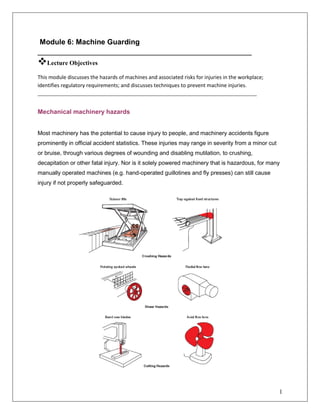
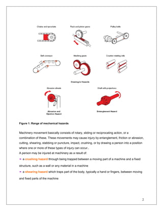
1
Module 6: Machine Guarding
______________________________________________
Lecture Objectives
This module discusses the hazards of machines and associated risks for injuries in the workplace;
identifies regulatory requirements; and discusses techniques to prevent machine injuries.
_____________________________________________________________________
Mechanical machinery hazards
Most machinery has the potential to cause injury to people, and machinery accidents figure
prominently in official accident statistics. These injuries may range in severity from a minor cut
or bruise, through various degrees of wounding and disabling mutilation, to crushing,
decapitation or other fatal injury. Nor is it solely powered machinery that is hazardous, for many
manually operated machines (e.g. hand-operated guillotines and fly presses) can still cause
injury if not properly safeguarded.
2
Figure 1: Range of mechanical hazards
Machinery movement basically consists of rotary, sliding or reciprocating action, or a
combination of these. These movements may cause injury by entanglement, friction or abrasion,
cutting, shearing, stabbing or puncture, impact, crushing, or by drawing a person into a position
where one or more of these types of injury can occur..
A person may be injured at machinery as a result of:
➤ a crushing hazard through being trapped between a moving part of a machine and a fixed
structure, such as a wall or any material in a machine
➤ a shearing hazard which traps part of the body, typically a hand or fingers, between moving
and fixed parts of the machine
3
➤ a cutting or severing hazard through contact with a cutting edge, such as a band saw or
rotating cutting disc
➤ entanglement hazard with the machinery which grips loose clothing, hair or working
material, such as emery paper, around revolving exposed parts of the machinery. The smaller
the diameter of the revolving part the easier it is to get a wrap or entanglement
➤ a drawing-in or trapping hazard such as between in-running gear wheels or rollers or
between belts and pulley drives
➤ an impact hazard when a moving part directly strikes a person, such as with the accidental
movement of a robot’s working arm when maintenance is taking place
➤ a stabbing or puncture hazard through ejection of particles from a machine or a sharp
operating component like a needle on a sewing machine
➤ contact with a friction or abrasion hazard, for example, on grinding wheels or sanding
machines
➤ high pressure fluid injection (ejection hazard), for example, from a hydraulic system leak.
In practice, injury may involve several of these at once, for example, contact, followed by
entanglement of clothing, followed by trapping.
Practical safeguards
The OSH Act 2004 requires that access to dangerous parts of machinery should be prevented
in a preferred order or hierarchy of control methods. The standard required is a ‘practicable’
one, so that the only acceptable reason for non-compliance is that there is no technical solution.
Cost is not a factor. The levels of protection required are, in order of implementation:
➤ fixed enclosing guarding
➤ other guards or protection devices, such as interlocked guards and pressure sensitive mats
➤ protection appliances, such as jigs, holders and push-sticks and
➤ the provision of information, instruction, training and supervision. Since the mechanical
hazard of machinery arises principally from someone coming into contact or entanglement with
4
dangerous components, risk reduction is based on preventing this contact occurring. This may
be by means of:
➤ a physical barrier between the individual and the component (e.g. a fixed enclosing guard)
➤ a device which only allows access when the component is in a safe state (e.g. an interlocked
guard which prevents the machine starting unless a guard is closed and acts to stop the
machine if the guard is opened) or
➤ a device which detects that the individual is entering a risk area and then stops the machine
(e.g. certain photoelectric guards and pressure-sensitive mats). The best method should,
ideally, be chosen by the designer as early in the life of the machine as possible. It is often
found that safeguards which are ‘bolted on’ instead of ‘built in’ are not only less effective in
reducing risk, but are also more likely to inhibit the normal operation of the machine. In addition,
they may in themselves create hazards and are likely to be difficult and hence expensive to
maintain.
Fixed guards
Fixed guards have the advantage of being simple, always in position, difficult to remove and
almost maintenance free. Their disadvantage is that they do not always properly prevent
access; they are often left off by maintenance staff and can create difficulties for the operation of
the machine.
A fixed guard has no moving parts and should, by its design, prevent access to the dangerous
parts of the machinery. It must be of robust construction and sufficient to withstand the stresses
of the process and environmental conditions. If visibility or free air flow (e.g. for cooling) are
necessary, this must be allowed for in the design and construction of the guard. If the guard can
be opened or removed, this must only be possible with the
aid of a tool.
An alternative fixed guard is the distance fixed guard, which does not completely enclose a
hazard, but which reduces access by virtue of its dimensions and its distance from the hazard.
Where perimeter-fence guards are used, the guard must follow the contours of the machinery
as far as possible, thus minimizing space between the guard and the machinery. With this type
5
of guard it is important that the safety devices and operating systems prevent the machinery
being operated with the guards closed and someone inside the guard, i.e. in the danger area.
Figure 2 shows a range of fixed guards for some of the examples shown in Figure 1.
Figure 2: Range of fixed guards
Adjustable guards
User adjusted guard
These are fixed or movable guards, which are adjustable for a particular operation during which
they remain fixed. They are particularly used with machine tools where some access to the
dangerous part is required (e.g. drills, circular saws, milling machines) and where the clearance
required will vary (e.g. with the size of the cutter in use on a horizontal milling machine or with
6
the size of the timber being sawn on a circular saw bench) (Figure 3). Adjustable guards may
be the only option with cutting tools, which are otherwise very difficult to guard, but they have
the disadvantage of requiring frequent readjustment.
Figure 3: Adjustable guard for a rotating shaft, such as a pedestal drill
By the nature of the machines on which they are most frequently used, there will still be some
access to the dangerous parts, so these machines must only be used by suitably trained
operators. Jigs, push sticks and false tables must be used wherever possible to minimize
hazards during the feeding of the work-piece. The. working area should be well lit and kept free
of anything which might cause the operator to slip or trip.
Self-adjusting guard
A self-adjusting guard is one which adjusts itself to accommodate, for example, the passage of
material. A good example is the spring-loaded guard fitted to many portable circular saws.
As with adjustable guards (see above) they only provide a partial solution in that they may well
still allow access to the dangerous part of the machinery. They require careful maintenance to
ensure they work to the best advantage (Figure 4).
Figure 4: Self adjusting guard on a wood saw
7
Interlocking guard
The advantages of interlocked guards are that they allow safe access to operate and maintain
the machine without dismantling the safety devices. Their disadvantage stems from the constant
need to ensure that they are operating correctly and designed to be fail safe. Maintenance and
inspection procedures must be very strict. This is a guard which is movable (or which has a
movable part) whose movement is connected with the power or control system of the machine.
An interlocking guard must be so connected to the machine controls such that:
➤ until the guard is closed the interlock prevents the machinery from operating by interrupting
the power medium
➤ either the guard remains locked closed until the risk of injury from the hazard has passed or
opening the guard causes the hazard to be eliminated before access is possible.
A passenger lift or hoist is a good illustration of these principles: the lift will not move unless the
doors are closed, and the doors remain closed and locked until the lift is stationary and in such
a position that it is safe for the doors to open. Special care is needed with systems which have
stored energy. This might be the momentum of a heavy moving part, stored pressure in a
hydraulic or pneumatic system, or even the simple fact of a part being able to move under
gravity even though the power is disconnected. In these situations, dangerous movement may
continue or be possible with the guard open, and these factors need to be considered in the
overall design. Braking devices (to arrest movement when the guard is opened) or delay
devices (to prevent the guard opening until the machinery is safe) may be needed. All
interlocking systems must be designed to minimize the risk of failure to-danger and should not
be easy to defeat (Figure 5).
Figure 5: Typical sliding and hinged interlocking guards
8
Other safety devices
Trip devices
A trip device does not physically keep people away but detects when a person approaches
close to a danger point. It should be designed to stop the machine before injury occurs. A trip
device depends on the ability of the machine to stop quickly and in some cases a brake may
need to be fi tted. Trip devices can be:
➤ mechanical in the form of a bar or barrier
➤ electrical in the form of a trip switch on an actuator rod, wire or other mechanism
➤ photoelectric or other type of presence-sensing device
➤ pressure-sensitive mat.
They should be designed to be self-resetting so that the machine must be restarted using the
normal procedure (Figure 6).
Figure 6: Schematic diagram of a telescopic trip device fitted to a redial drill.
9
Two-handed control devices
These are devices which require the operator to have both hands in a safe place (the location of
the controls) before the machine can be operated. They are an option on machinery that is
otherwise very difficult to guard but they have the drawback that they only protect the operator’s
hands. It is therefore essential that the design does not allow any other part of the operator’s
body to enter the danger zone during operation. More significantly, they give no protection to
anyone other than the operator. Where two-handed controls are used, the following principles
must be followed:
➤ the controls should be so placed, separated and protected as to prevent spanning with one
hand only, being operated with one hand and another part of the body, or being readily bridged
➤ it should not be possible to set the dangerous parts in motion unless the controls are
operated within approximately 0.5 seconds of each other. Having set the dangerous parts in
motion, it should not be possible to do so again until both controls have been
returned to their off position
➤ movement of the dangerous parts should be arrested immediately or, where appropriate,
arrested and reversed if one or both controls are released while there is still danger from
movement of the parts
➤ the hand controls should be situated at such a distance from the danger point that, on
releasing the controls, it is not possible for the operator to reach the danger point before the
motion of the dangerous parts has been arrested or, where appropriate, arrested and reversed
(Figure 7).
Figure 7: Pedestal mounted free standing two-hand control device
10
Hold-to-run control
This is a control which allows movement of the machinery only as long as the control is held in a
set position. The control must return automatically to the stop position when released. Where
the machinery runs at crawl speed, this speed should be kept as low as practicable.
Hold-to-run controls give even less protection to the operator than two-handed controls and
have the same main drawback in that they give no protection to anyone other than the operator.
However, along with limited movement devices (systems which permit only a limited amount of
machine movement on each occasion that the control is operated and are often called ‘inching
devices’), they are extremely relevant to operations such as setting, where access may
well be necessary and safeguarding by any other means is difficult to achieve.
Guard construction
The design and construction of guards must be appropriate to the risks identified and the mode
of operation of the machinery in question. The following factors should be considered:
➤ strength – guards should be adequate for the purpose, able to resist the forces and vibration
involved, and able to withstand impact (where applicable)
➤ weight and size – in relation to the need to remove and replace the guard during
maintenance
➤ compatibility with materials being processed and lubricants etc.
➤ hygiene and the need to comply with food safety regulations
➤ visibility – it may be necessary to see through the guard for both operational and safety
reasons
➤ noise attenuation – guards can often be used to reduce the noise levels produced by a
machine. Conversely the resonance of large undamped panels may exacerbate the noise
problem
➤ enabling a free fl ow of air – where necessary (e.g. for ventilation)
➤ avoidance of additional hazards – for example, free of sharp edges
11
➤ ease of maintenance and cleanliness
➤ openings – the size of openings and their distance from the dangerous parts should not allow
anyone to be able to reach into a danger zone. These values can be determined by experiment
or by reference to standard tables. If doing so by experiment, it is essential that the machine is
first stopped and made safe (e.g. by isolation).
Module 6: Machine Guarding Revision Questions
1. Why is it important to use machines only after instruction/demonstration by the
teacher?
2. Why are ties a potential danger, especially when using a machine?
3. If a pupil has long hair what should he/she do when using a machine?
4. When using the machine drill - why should the work be held in a vice?
5. Why is it important to report damaged/defective tools and equipment to the teacher?
6. What types of controls and safety mechanisms do vehicles and mobile equipment have
to protect employees operating these vehicles or mobile equipment?
7. What workplace safety practices has your company or industry implemented to protect
employees who use or work near portable powered hand tools?
8. Identify the main causes of machine accidents
9. Explain the hazards associated with the following actions:
a. Cutting
b. Punching and
c. shearing

machine_guarding.pdf

  • 1.
    1 Module 6: MachineGuarding ______________________________________________ Lecture Objectives This module discusses the hazards of machines and associated risks for injuries in the workplace; identifies regulatory requirements; and discusses techniques to prevent machine injuries. _____________________________________________________________________ Mechanical machinery hazards Most machinery has the potential to cause injury to people, and machinery accidents figure prominently in official accident statistics. These injuries may range in severity from a minor cut or bruise, through various degrees of wounding and disabling mutilation, to crushing, decapitation or other fatal injury. Nor is it solely powered machinery that is hazardous, for many manually operated machines (e.g. hand-operated guillotines and fly presses) can still cause injury if not properly safeguarded.
  • 2.
    2 Figure 1: Rangeof mechanical hazards Machinery movement basically consists of rotary, sliding or reciprocating action, or a combination of these. These movements may cause injury by entanglement, friction or abrasion, cutting, shearing, stabbing or puncture, impact, crushing, or by drawing a person into a position where one or more of these types of injury can occur.. A person may be injured at machinery as a result of: ➤ a crushing hazard through being trapped between a moving part of a machine and a fixed structure, such as a wall or any material in a machine ➤ a shearing hazard which traps part of the body, typically a hand or fingers, between moving and fixed parts of the machine
  • 3.
    3 ➤ a cuttingor severing hazard through contact with a cutting edge, such as a band saw or rotating cutting disc ➤ entanglement hazard with the machinery which grips loose clothing, hair or working material, such as emery paper, around revolving exposed parts of the machinery. The smaller the diameter of the revolving part the easier it is to get a wrap or entanglement ➤ a drawing-in or trapping hazard such as between in-running gear wheels or rollers or between belts and pulley drives ➤ an impact hazard when a moving part directly strikes a person, such as with the accidental movement of a robot’s working arm when maintenance is taking place ➤ a stabbing or puncture hazard through ejection of particles from a machine or a sharp operating component like a needle on a sewing machine ➤ contact with a friction or abrasion hazard, for example, on grinding wheels or sanding machines ➤ high pressure fluid injection (ejection hazard), for example, from a hydraulic system leak. In practice, injury may involve several of these at once, for example, contact, followed by entanglement of clothing, followed by trapping. Practical safeguards The OSH Act 2004 requires that access to dangerous parts of machinery should be prevented in a preferred order or hierarchy of control methods. The standard required is a ‘practicable’ one, so that the only acceptable reason for non-compliance is that there is no technical solution. Cost is not a factor. The levels of protection required are, in order of implementation: ➤ fixed enclosing guarding ➤ other guards or protection devices, such as interlocked guards and pressure sensitive mats ➤ protection appliances, such as jigs, holders and push-sticks and ➤ the provision of information, instruction, training and supervision. Since the mechanical hazard of machinery arises principally from someone coming into contact or entanglement with
  • 4.
    4 dangerous components, riskreduction is based on preventing this contact occurring. This may be by means of: ➤ a physical barrier between the individual and the component (e.g. a fixed enclosing guard) ➤ a device which only allows access when the component is in a safe state (e.g. an interlocked guard which prevents the machine starting unless a guard is closed and acts to stop the machine if the guard is opened) or ➤ a device which detects that the individual is entering a risk area and then stops the machine (e.g. certain photoelectric guards and pressure-sensitive mats). The best method should, ideally, be chosen by the designer as early in the life of the machine as possible. It is often found that safeguards which are ‘bolted on’ instead of ‘built in’ are not only less effective in reducing risk, but are also more likely to inhibit the normal operation of the machine. In addition, they may in themselves create hazards and are likely to be difficult and hence expensive to maintain. Fixed guards Fixed guards have the advantage of being simple, always in position, difficult to remove and almost maintenance free. Their disadvantage is that they do not always properly prevent access; they are often left off by maintenance staff and can create difficulties for the operation of the machine. A fixed guard has no moving parts and should, by its design, prevent access to the dangerous parts of the machinery. It must be of robust construction and sufficient to withstand the stresses of the process and environmental conditions. If visibility or free air flow (e.g. for cooling) are necessary, this must be allowed for in the design and construction of the guard. If the guard can be opened or removed, this must only be possible with the aid of a tool. An alternative fixed guard is the distance fixed guard, which does not completely enclose a hazard, but which reduces access by virtue of its dimensions and its distance from the hazard. Where perimeter-fence guards are used, the guard must follow the contours of the machinery as far as possible, thus minimizing space between the guard and the machinery. With this type
  • 5.
    5 of guard itis important that the safety devices and operating systems prevent the machinery being operated with the guards closed and someone inside the guard, i.e. in the danger area. Figure 2 shows a range of fixed guards for some of the examples shown in Figure 1. Figure 2: Range of fixed guards Adjustable guards User adjusted guard These are fixed or movable guards, which are adjustable for a particular operation during which they remain fixed. They are particularly used with machine tools where some access to the dangerous part is required (e.g. drills, circular saws, milling machines) and where the clearance required will vary (e.g. with the size of the cutter in use on a horizontal milling machine or with
  • 6.
    6 the size ofthe timber being sawn on a circular saw bench) (Figure 3). Adjustable guards may be the only option with cutting tools, which are otherwise very difficult to guard, but they have the disadvantage of requiring frequent readjustment. Figure 3: Adjustable guard for a rotating shaft, such as a pedestal drill By the nature of the machines on which they are most frequently used, there will still be some access to the dangerous parts, so these machines must only be used by suitably trained operators. Jigs, push sticks and false tables must be used wherever possible to minimize hazards during the feeding of the work-piece. The. working area should be well lit and kept free of anything which might cause the operator to slip or trip. Self-adjusting guard A self-adjusting guard is one which adjusts itself to accommodate, for example, the passage of material. A good example is the spring-loaded guard fitted to many portable circular saws. As with adjustable guards (see above) they only provide a partial solution in that they may well still allow access to the dangerous part of the machinery. They require careful maintenance to ensure they work to the best advantage (Figure 4). Figure 4: Self adjusting guard on a wood saw
  • 7.
    7 Interlocking guard The advantagesof interlocked guards are that they allow safe access to operate and maintain the machine without dismantling the safety devices. Their disadvantage stems from the constant need to ensure that they are operating correctly and designed to be fail safe. Maintenance and inspection procedures must be very strict. This is a guard which is movable (or which has a movable part) whose movement is connected with the power or control system of the machine. An interlocking guard must be so connected to the machine controls such that: ➤ until the guard is closed the interlock prevents the machinery from operating by interrupting the power medium ➤ either the guard remains locked closed until the risk of injury from the hazard has passed or opening the guard causes the hazard to be eliminated before access is possible. A passenger lift or hoist is a good illustration of these principles: the lift will not move unless the doors are closed, and the doors remain closed and locked until the lift is stationary and in such a position that it is safe for the doors to open. Special care is needed with systems which have stored energy. This might be the momentum of a heavy moving part, stored pressure in a hydraulic or pneumatic system, or even the simple fact of a part being able to move under gravity even though the power is disconnected. In these situations, dangerous movement may continue or be possible with the guard open, and these factors need to be considered in the overall design. Braking devices (to arrest movement when the guard is opened) or delay devices (to prevent the guard opening until the machinery is safe) may be needed. All interlocking systems must be designed to minimize the risk of failure to-danger and should not be easy to defeat (Figure 5). Figure 5: Typical sliding and hinged interlocking guards
  • 8.
    8 Other safety devices Tripdevices A trip device does not physically keep people away but detects when a person approaches close to a danger point. It should be designed to stop the machine before injury occurs. A trip device depends on the ability of the machine to stop quickly and in some cases a brake may need to be fi tted. Trip devices can be: ➤ mechanical in the form of a bar or barrier ➤ electrical in the form of a trip switch on an actuator rod, wire or other mechanism ➤ photoelectric or other type of presence-sensing device ➤ pressure-sensitive mat. They should be designed to be self-resetting so that the machine must be restarted using the normal procedure (Figure 6). Figure 6: Schematic diagram of a telescopic trip device fitted to a redial drill.
  • 9.
    9 Two-handed control devices Theseare devices which require the operator to have both hands in a safe place (the location of the controls) before the machine can be operated. They are an option on machinery that is otherwise very difficult to guard but they have the drawback that they only protect the operator’s hands. It is therefore essential that the design does not allow any other part of the operator’s body to enter the danger zone during operation. More significantly, they give no protection to anyone other than the operator. Where two-handed controls are used, the following principles must be followed: ➤ the controls should be so placed, separated and protected as to prevent spanning with one hand only, being operated with one hand and another part of the body, or being readily bridged ➤ it should not be possible to set the dangerous parts in motion unless the controls are operated within approximately 0.5 seconds of each other. Having set the dangerous parts in motion, it should not be possible to do so again until both controls have been returned to their off position ➤ movement of the dangerous parts should be arrested immediately or, where appropriate, arrested and reversed if one or both controls are released while there is still danger from movement of the parts ➤ the hand controls should be situated at such a distance from the danger point that, on releasing the controls, it is not possible for the operator to reach the danger point before the motion of the dangerous parts has been arrested or, where appropriate, arrested and reversed (Figure 7). Figure 7: Pedestal mounted free standing two-hand control device
  • 10.
    10 Hold-to-run control This isa control which allows movement of the machinery only as long as the control is held in a set position. The control must return automatically to the stop position when released. Where the machinery runs at crawl speed, this speed should be kept as low as practicable. Hold-to-run controls give even less protection to the operator than two-handed controls and have the same main drawback in that they give no protection to anyone other than the operator. However, along with limited movement devices (systems which permit only a limited amount of machine movement on each occasion that the control is operated and are often called ‘inching devices’), they are extremely relevant to operations such as setting, where access may well be necessary and safeguarding by any other means is difficult to achieve. Guard construction The design and construction of guards must be appropriate to the risks identified and the mode of operation of the machinery in question. The following factors should be considered: ➤ strength – guards should be adequate for the purpose, able to resist the forces and vibration involved, and able to withstand impact (where applicable) ➤ weight and size – in relation to the need to remove and replace the guard during maintenance ➤ compatibility with materials being processed and lubricants etc. ➤ hygiene and the need to comply with food safety regulations ➤ visibility – it may be necessary to see through the guard for both operational and safety reasons ➤ noise attenuation – guards can often be used to reduce the noise levels produced by a machine. Conversely the resonance of large undamped panels may exacerbate the noise problem ➤ enabling a free fl ow of air – where necessary (e.g. for ventilation) ➤ avoidance of additional hazards – for example, free of sharp edges
  • 11.
    11 ➤ ease ofmaintenance and cleanliness ➤ openings – the size of openings and their distance from the dangerous parts should not allow anyone to be able to reach into a danger zone. These values can be determined by experiment or by reference to standard tables. If doing so by experiment, it is essential that the machine is first stopped and made safe (e.g. by isolation). Module 6: Machine Guarding Revision Questions 1. Why is it important to use machines only after instruction/demonstration by the teacher? 2. Why are ties a potential danger, especially when using a machine? 3. If a pupil has long hair what should he/she do when using a machine? 4. When using the machine drill - why should the work be held in a vice? 5. Why is it important to report damaged/defective tools and equipment to the teacher? 6. What types of controls and safety mechanisms do vehicles and mobile equipment have to protect employees operating these vehicles or mobile equipment? 7. What workplace safety practices has your company or industry implemented to protect employees who use or work near portable powered hand tools? 8. Identify the main causes of machine accidents 9. Explain the hazards associated with the following actions: a. Cutting b. Punching and c. shearing