Downloaded 158 times

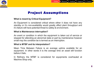
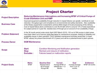
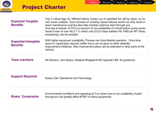
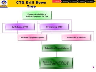
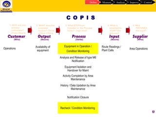
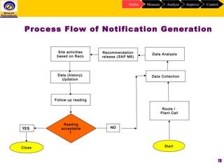
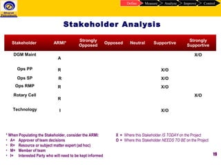
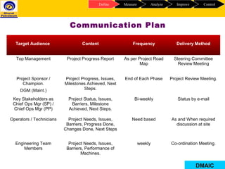
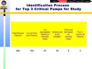
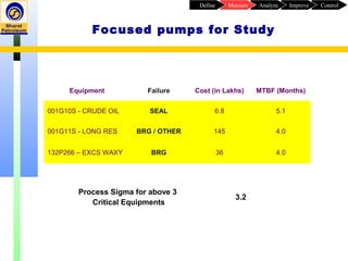
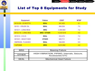
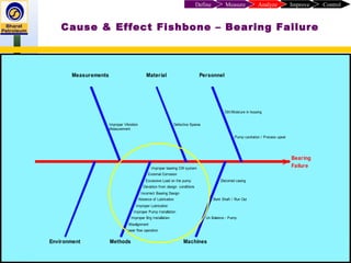
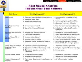
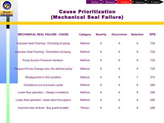


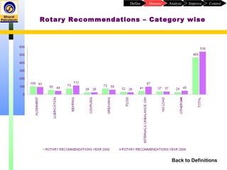
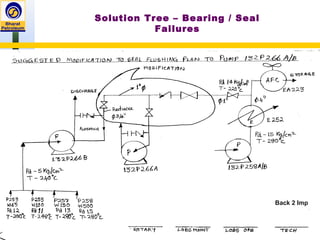
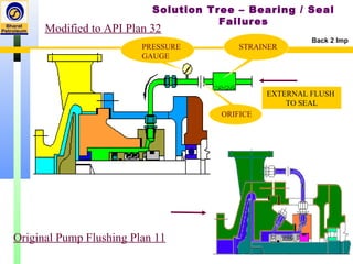

This document provides details of a Six Sigma project aimed at reducing maintenance interruptions and increasing the mean time between failures (MTBF) of critical equipment at a refinery. The project focuses on pumps in critical units like crude distillation and residue manufacturing plant. The document defines the problem statement, goals, scope and assumptions. It presents analysis of failure data to identify the top 3 pumps for study based on number of repeat failures and their impact. Process flow, stakeholder mapping, communication plan and initial measurement efforts like fishbone diagrams and 5 whys are also included. The project aims to improve reliability and availability of critical pumps through root cause analysis and elimination of repeat failures.


![002 Maintenance M Overview 20 06 06[1]](https://cdn.slidesharecdn.com/ss_thumbnails/002-maintenance-m-overview-20-06-061-1221944333735887-9-thumbnail.jpg?width=640&height=640&fit=bounds)


