- Pall Corporation provides filtration and separation technologies that help customers conserve energy and resources while protecting the environment. Their technologies purify water, consume less energy, enable alternative energy sources, and minimize emissions and waste.
- A study observed that 70% of mechanical failures are due to surface degradation, with 50% from mechanical wear and 20% from corrosion. Proper filtration is key to managing contaminants and preventing wear.
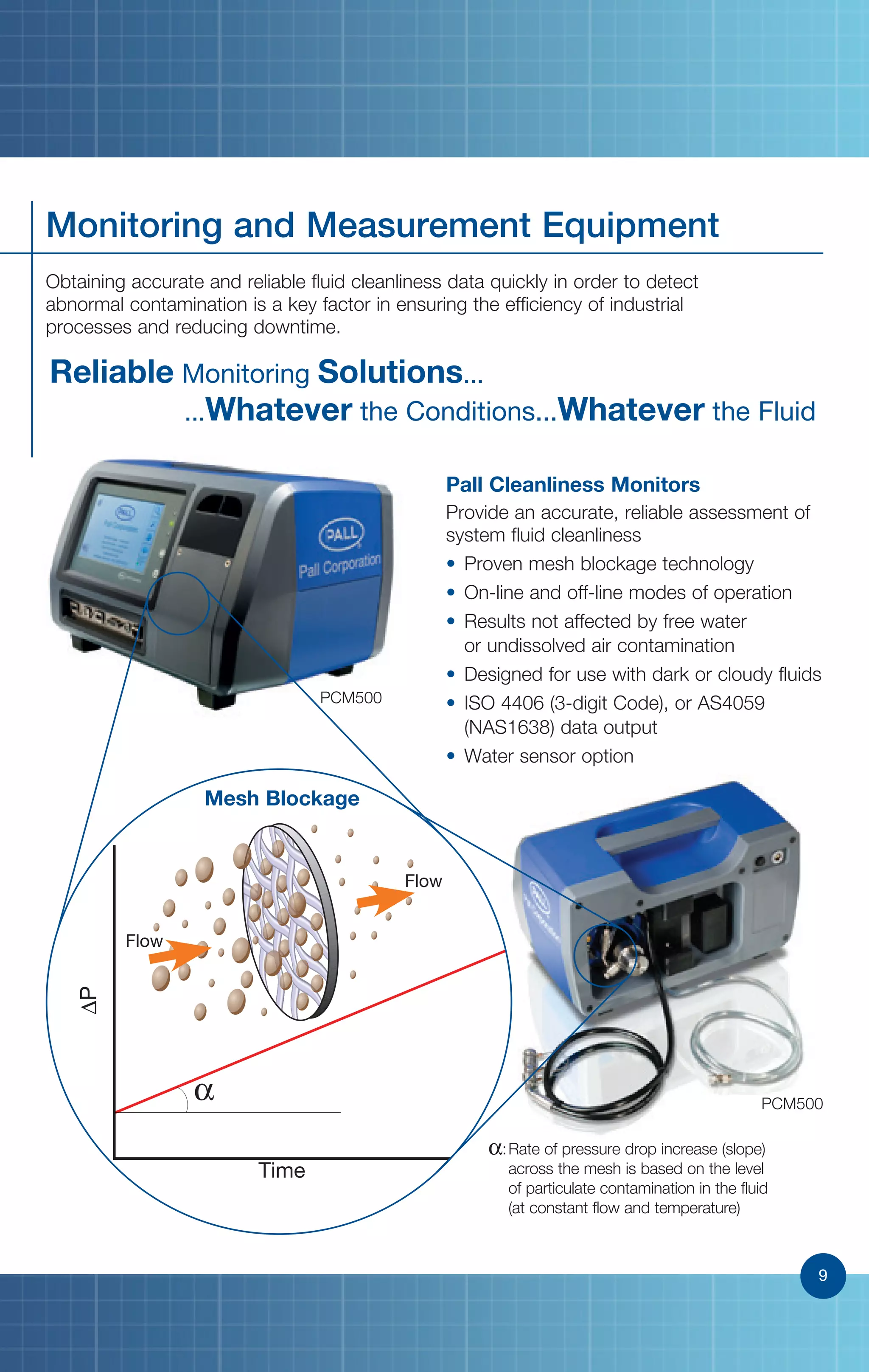
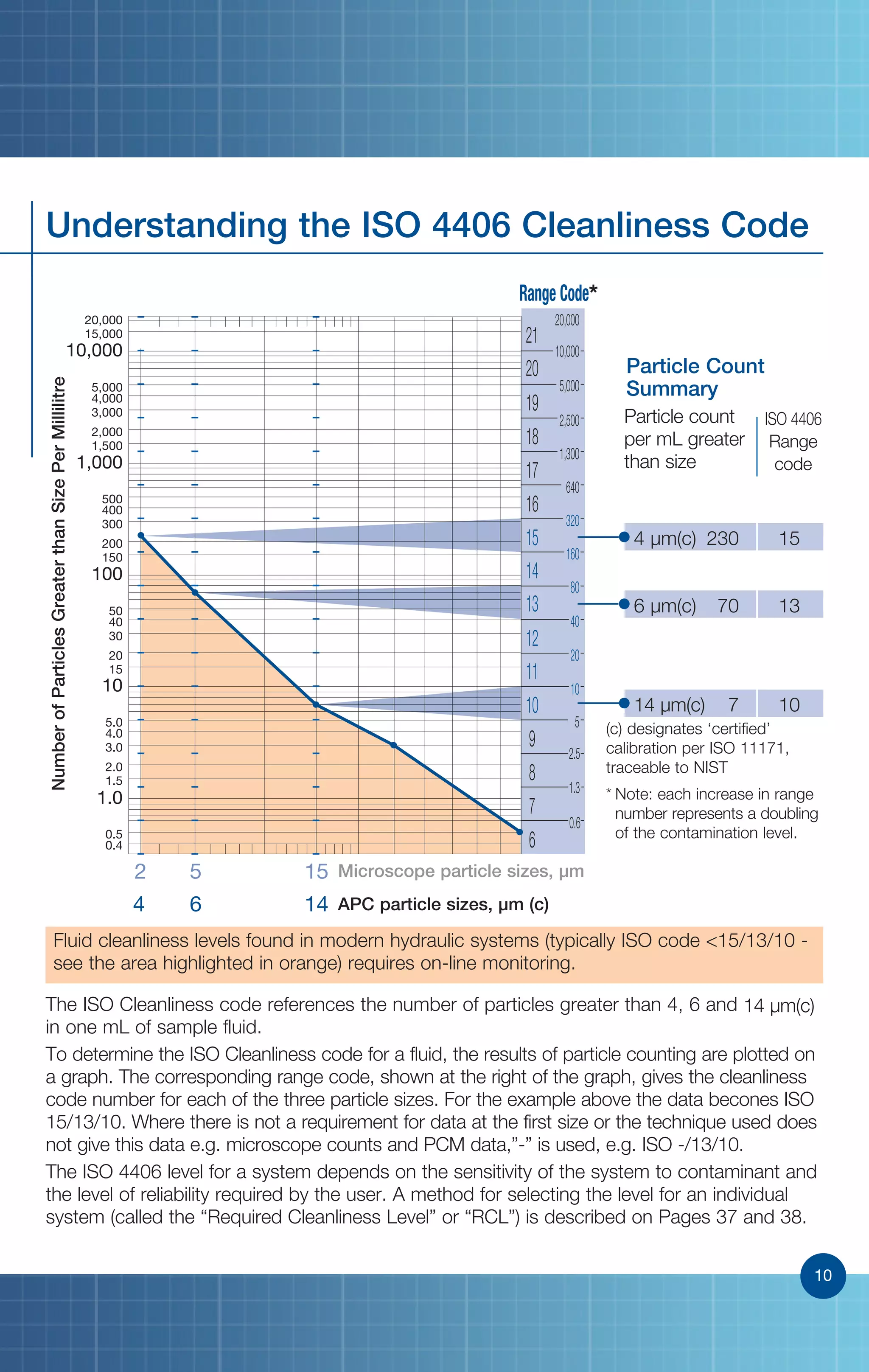
- ISO 4406 cleanliness codes are used to specify particulate contamination levels in hydraulic fluids, with higher numbers indicating dirtier fluid. On-line monitoring is needed to maintain cleanliness levels of ISO 15/13/10 or better required by modern hydraulic systems.
This is the Highly Detailed factory service repair manual for theMERCURY MERCRUISER MARINE ENGINE V-8 DIESEL, D7.3L D-TRONIC 1998 , this Service Manual has detailed illustrations as well as step by step instructions,It is 100 percents complete and intact. they are specifically written for the do-it-yourself-er as well as the experienced mechanic.MERCURY MERCRUISER MARINE ENGINE V-8 DIESEL, D7.3L D-TRONIC 1998 Service Repair Workshop Manual provides step-by-step instructions based on the complete dis-assembly of the machine. It is this level of detail, along with hundreds of photos and illustrations, that guide the reader through each service and repair procedure. Complete download comes in pdf format which can work under all PC based windows operating system and Mac also, All pages are printable. Using this repair manual is an inexpensive way to keep your vehicle working properly.
Service Repair Manual Covers:
Important Information
Removal and Installation
Engine Mechanical
Electrical System
Fuel System
Cooling Sytem
Intake and Exhaust System
Power Steering System
File Format: PDF
Compatible: All Versions of Windows & Mac
Language: English
Requirements: Adobe PDF Reader
NO waiting, Buy from responsible seller and get INSTANT DOWNLOAD, Without wasting your hard-owned money on uncertainty or surprise! All pages are is great to haveMERCURY MERCRUISER MARINE ENGINE V-8 DIESEL, D7.3L D-TRONIC 1998 Service Repair Workshop Manual.
Looking for some other Service Repair Manual,please check:
https://www.aservicemanualpdf.com/
Thanks for visiting!
8
The document is a technical data sheet from NTPC Limited, a Government of India enterprise, regarding flue gas desulphurisation (FGD) systems. It contains instructions for bidders on providing essential input/interface data along with the bid. The data sheet includes chapters on essential input/interface data to be provided, technical information to be submitted along with the bid, and technical information to be submitted after contract award. It requires bidders to provide auxiliary steam requirements, cooling water requirements, process water requirements, waste water characteristics and other interface data.
Man industrial diesel engine d 2866 le..service repair manualregdfcgvdgvf
This document provides instructions and safety information for repairing diesel engines. It begins with introductions and safety warnings for working on engines. The document then provides schematics of the engine's fuel, lubrication, and cooling systems. The remainder of the document contains step-by-step instructions for maintenance, repair, and overhaul procedures involving the engine's major components and systems.
PERKINS 2200 SERIES 2206D-E13TA INDUSTRIAL ENGINE Service Repair Manualhfjskefmmmse
The document provides an overview of the electronic control system used in Perkins industrial engines. It describes the main components, capabilities, and troubleshooting process. The electronic control module (ECM) controls engine operation through sensors and maps in its software. It interfaces with machine applications and detects faults through diagnostic trouble codes. Proper service tools are required to communicate with the ECM and diagnose issues.
Mechanical Design of a Heat Exchanger.pdfsarhanfarook
The document describes the design of a heat exchanger to heat distilled fatty acid from 55°C to 85°C using steam as the hot fluid. Key aspects of the design include:
- Using 278 stainless steel tubes in a triangular pitch arrangement with a total heat transfer area of 41.36 m2
- The hot steam enters at 200°C and exits at 138.99°C, with a dry fraction of 0.865988059
- Dimensions of the shell, tubesheet, baffles and other components are calculated and specified
- The design is compared to an existing heat exchanger, with some differences in parameters like number of tubes and tube layout
This document provides an instruction manual and parts list for various pumps. It includes specifications for 5 pumps to be used on a ship including their type, flow rate, power requirements and other details. The document provides safety, installation, operation and maintenance instructions for horizontal gear pumps. It describes the pump components, proper installation including alignment, start-up procedures, preventative maintenance, and rules for assembly and disassembly.
This document provides a user's guide for the TELYS control unit. It describes the standard configuration and options of the control unit, including the front and rear panels. It also outlines the main menus for actions, information, settings, and country selection. The document explains how to view alarms and faults, and view engine fault codes. It details the different access levels and exterior communication options. Finally, it provides instructions for manual and automatic operation of the generating set, as well as maintenance and troubleshooting.
Caterpillar Diesel Engine Control Systems [PDF, ENG, 588 KB].pdfEguima Guima
This document discusses diesel engine control systems, including engine protection and monitoring system parameters for various engine systems, as well as control systems for engines using Electronic Unit Injection (EUI) and Mechanical Unit Injection (MUI). It covers topics such as lubrication, cooling, fuel, air, exhaust, and off-engine systems; control modules; alarm modules; communication methods; and wiring considerations. The document provides an overview of the key components and considerations for diesel engine control and monitoring systems.
This is the Highly Detailed factory service repair manual for theMERCURY MERCRUISER MARINE ENGINE V-8 DIESEL, D7.3L D-TRONIC 1998 , this Service Manual has detailed illustrations as well as step by step instructions,It is 100 percents complete and intact. they are specifically written for the do-it-yourself-er as well as the experienced mechanic.MERCURY MERCRUISER MARINE ENGINE V-8 DIESEL, D7.3L D-TRONIC 1998 Service Repair Workshop Manual provides step-by-step instructions based on the complete dis-assembly of the machine. It is this level of detail, along with hundreds of photos and illustrations, that guide the reader through each service and repair procedure. Complete download comes in pdf format which can work under all PC based windows operating system and Mac also, All pages are printable. Using this repair manual is an inexpensive way to keep your vehicle working properly.
Service Repair Manual Covers:
Important Information
Removal and Installation
Engine Mechanical
Electrical System
Fuel System
Cooling Sytem
Intake and Exhaust System
Power Steering System
File Format: PDF
Compatible: All Versions of Windows & Mac
Language: English
Requirements: Adobe PDF Reader
NO waiting, Buy from responsible seller and get INSTANT DOWNLOAD, Without wasting your hard-owned money on uncertainty or surprise! All pages are is great to haveMERCURY MERCRUISER MARINE ENGINE V-8 DIESEL, D7.3L D-TRONIC 1998 Service Repair Workshop Manual.
Looking for some other Service Repair Manual,please check:
https://www.aservicemanualpdf.com/
Thanks for visiting!
8
PERFORMANCE EVALUATION AND OPTIMIZATION OF AIR PREHEATER IN THERMAL POWER PLANTIAEME Publication
This paper presents a performance evaluation and optimization method of an air preheater based on routine
operation data measured onsite at LANCO-UPCL, Nagarjuna thermal power plant Padubidri, Karnataka, India. The work
focuses on the performance of Regenerative type air pre heater (model LAP 13494/2200). The performances were
evaluated before and after radial sector plate clearance adjustments with air preheater tests, and improvement is seen
along with air preheater optimization.
The document discusses excess air and heat distribution in boilers. It explains that excess air above the theoretical minimum is needed for complete combustion due to imperfect mixing of fuel and air. Typical excess air values range from 5-60% depending on the fuel and furnace type. Heat distribution systems discussed include steam radiators, which use steam piped through the home, and hot water radiators, which can be zoned to improve efficiency. Regular maintenance of radiators includes bleeding air and cleaning/replacing steam traps and air vents.
Jcb isuzu 4 hk1 engine service repair manualdujjsjekkekmme
This document provides service information for Isuzu 4HK1 and 6HK1 diesel engines. It includes removal and installation instructions for various engine components as well as specifications and inspection guidelines. The document covers cylinder head, camshaft, crankshaft, pistons, connecting rods, valves, timing gears, turbocharger and other parts. Precautions are provided for each procedure.
Yale c879 glc70 vx lift truck service repair manualjkmsme ekdmm
This document provides instructions for replacing the hood, seat, dash, and side covers on a lift truck. Key steps include removing the floor plate, side panels, fender covers, steering column covers, dash, kick panel, and seal plate. The gas springs and hinge screws are then removed to lift the hood off the frame. Reinstallation involves reversing these steps, ensuring the hood latch striker aligns properly and the hood closes fully with two clicks.
El técnico con conocimientos en Mecánica Automotriz necesita que cuente a la mano con los datos técnicos de los fabricantes de los diferentes modelos con los ajustes a debe aplicar a los motores,
The document is a service manual for trucks that provides wiring diagrams and component information. It includes an index listing over 125 component wiring diagrams by page number. Each diagram shows the wiring for a specific component and includes symbols to identify things like connectors, fuses, splices and wire colors. The manual also includes sections with information on grounds, connectors, abbreviations and feedback.
Discussion on Urea Product Quality by Prem Baboo.pdfPremBaboo4
Dear friends today we will discuss on urea product quality. What are the factors on which urea product quality depends? How to improve urea product quality. Urea produced by prilling and granulation rout. In India Prilling is very popular and other countries Granulation rout is adopted. There are some merits and demerits are prilling and granulation routs. Different types of question with their answers
This document provides an overview and descriptions of the key components of an air preheater used at the Mongduong 2 560 MW Coal Fired Power Plant. It describes the rotor assembly, rotor seals, rotor drive unit, support and guide bearings, lube oil circulation unit, retractable sootblowers, water washing device, and fire fighting system. The air preheater transfers heat from flue gas to incoming combustion air using rotating heat transfer elements to increase the air temperature prior to combustion.
This document is a workshop manual for Perkins New 1000 Series diesel engines used in industrial and agricultural applications. It provides detailed instructions for servicing and repairing engine components. The manual contains 25 chapters covering general information, specifications, procedures for servicing components like the cylinder head, pistons, crankshaft, timing case, cylinder block, and systems like cooling, fuel, lubrication, and electrical equipment. It also includes data and dimensions for engine parts.
This document discusses various thermodynamic diagrams used for boiler calculations, including:
- Temperature-heat (T-Q) diagrams which show the heat transfer characteristics of heat exchangers and boiler components.
- Temperature-entropy (T-s) diagrams which represent the phases of steam/water and can display steam processes.
- Pressure-enthalpy (p-h) diagrams which make it easy to visualize the heat load shares on different boiler surfaces.
- Enthalpy-entropy (Mollier) diagrams which allow determining steam properties from two known parameters like pressure and temperature.
These diagrams provide useful visualization tools for designing and analyzing boiler performance and steam processes.
Este módulo introduce al estudiante al motor con tecnología ACERT C4.2, C6.4 / C4.4, C6.6. El estudiante aprenderá a identificar las etiquetas de seguridad del motor, conocerá las especificaciones técnicas de los modelos y realizará la inspección de mantenimiento siguiendo los procedimientos del manual. Completará hojas de trabajo para reforzar los conocimientos adquiridos.
This document provides an overview of variable frequency drives (VFDs) and their application in controlling rod pumps. It discusses how VFDs can improve efficiency by allowing motors to run at variable speeds rather than only full speed. VFDs reduce wear and harmonics by providing soft starting and stopping. The document then discusses issues like fluid pound and gas lock that can occur from over-pumping rod pumps. It explains that pump-off control is important to avoid these issues while maximizing production, and that VFDs provide benefits over across-the-line starters for pump control but still lack insights into downhole conditions.
1. The document discusses standards for assessing cleanliness of components in automotive fluid systems like lubricants, fuels, and hydraulics. Small particles can cause failures, so cleanliness is important.
2. It describes methods for extracting particles from components for analysis according to ISO standards. These include agitation extraction for hollow components, pressure rinsing extraction, and ultrasonic extraction.
3. Extraction methods are discussed for assessing the cleanliness of the inner surfaces of cylindrical components like pipes and hoses used in hydraulic, lubrication, and fuel systems. Validation of the extraction process is also covered.
Best Practices for Mobile Hydraulic DesignDesign World
With ever-rising fuel prices, designing efficient hydraulic systems can pay big dividends for users of mobile hydraulic vehicles. Join Design World as we take an in-depth look at three critical areas of mobile hydraulic system design: filtration, sensors and sealing. Our expert panel presents critical design tips and answering your questions.
Attendees will learn:
* How to use in-cylinder position sensing to optimize hydraulic functions on mobile equipment
* How to select the appropriate filtration grade for a specific application
* How do shaft requirements impact mobile hydraulic sealing products
The panel includes: Dr. Christian Bauer, Staff Scientist, Pall Corp.; Haubold “Hub” vom Berg, Technical Marketing Manager, MTS Sensors, Mobile Hydraulic; and Joel Johnson, VP of Technology, Simrit. The panel is moderated by Design World Editorial Director, Paul J. Heney.
This document provides an overview of clean-in-place (CIP) systems for cleaning process equipment. It discusses what CIP is, the advantages it provides over manual cleaning, and the key factors to consider in CIP system design including temperature, time, chemicals, mechanics, water quality, and monitoring systems. It also covers different types of CIP systems such as boil out, total loss, single use recirculation, and re-use systems. Design of the process equipment and piping is also discussed to enable effective cleaning.
When using the equipment of the AQUIFER company you save on:
- costs of installation of equipment
- the personnel (installations work in the automatic mode);
- expendables (in the course of work of installation public sorption materials of the Russian production are used, also in some cases when disinfecting food table salt is used)
The total cost of the equipment depends on productivity of installation, requirements imposed by the customer to the cleared water and a chemical composition of initial water.
This document discusses leak detection and repair for liquids and gases. It provides details on the types of equipment that can leak at facilities like refineries and chemical plants. It describes methods for identifying leaks using infrared cameras and measuring their size. The document also discusses implementing a leak detection and repair program to reduce pollution and costs from lost product. Regulated industries must inspect components like valves, pumps and compressors on a regular basis.
The document provides an overview of oxygen measurement solutions from Mettler-Toledo for process analytics. It discusses key drivers for oxygen measurement, amperometric measurement techniques, sensor design features, system offerings including transmitters and housings, and applications and case studies. The presentation aims to demonstrate how Mettler-Toledo's oxygen measurement solutions can help customers improve process control, product quality, and operational efficiency.
The right pressure transmitter can enhance production. The key to maximizing the return on oil and gas development projects rests with the maintenance and safety of your—sometimes—aging equipment.
This document discusses optimizing radiation monitoring sampling systems. It begins with background on effluent monitoring and key terms. The document then describes typical system configurations, factors that influence sampling efficiency like flow rate and particle size, and challenges with sampling points. It recommends analyzing the particle stream, developing a model to determine transmission efficiency based on particle properties, and setting the optimum flow rate. Maintaining and periodically reviewing systems is important to ensure representative sampling and proper dose measurement.
www.envimart.vn - ĐT: 028 77727979 - sales@envimart.vn - Nền tảng cung cấp thiết bị, vật tư ngành nước và môi trường. Chuyên cung cấp vật tư cho dự án xử lý nước sạch, nước thải và môi trường. Envimart luôn đồng hành, tin cậy với đối tác nhà thầu, nhà tích hợp và người sử dụng.
This document provides best practices for cleaning fiber optic connectors to prevent end face contamination. It discusses common sources of contamination like residues, dust, and electrostatic charge. Survey results show end face contamination is a major issue causing network failures. The document recommends using wet-dry cleaning methods with optical grade fluids to remove all contamination types. It provides cleaning product selection guidance and best practices for using wipes, sticks, and mechanical cleaners depending on contamination level. Following cleaning best practices can help reduce expensive repairs from human errors during installation.
SeptiTech STAAR Denitrification Wastewater PresentationBioMicrobics, Inc.
Residential & Commercial Denitrification Units for onsite wastewater treatment. Learn more about SeptiTech's Trickling Filter technology:
- Simple and Reliable Process
- Treats High Organic Loads
- Efficient in Removing Ammonia
- Handles and Recovers from Shock Loads
- Relatively Low Power Requirements
- Less Sludge than Suspended Growth Systems
- Moderate Operator Skill Level
- Low Operating Cost
How to Get the Best Data - Preventing Fouling of Online Wastewater SensorsXylem Inc.
Fouling is a common cause of measurement error which is preventable by probe design and with proper maintenance. The challenge, as with all types of equipment, is to learn the technology sufficiently to know what steps to take to achieve reliable measurements without excessive effort. This webinar will explain the technology for monitoring important wastewater process parameters with optical sensors and describe best practices for obtaining reliable, trouble-free, long-term ownership of process optical sensors, especially for monitoring solids. The information presented will include benchtop demonstrations of a novel ultrasonic cleaning mechanism and a full-scale demonstration of the effectiveness of UltraClean™ technology incorporated into an IQ SensorNet ViSolid® solids probe.
https://www.ysi.com/iqsn2020
The document provides an overview of a company that produces membrane contactor technology and auxiliary equipment for gas transfer applications. It describes the company's product lines which include hollow fiber membrane contactors in various sizes that can be used for applications like gas removal, absorption, and debubbling. It also lists the company's global locations and provides examples of system designs and performance data for gas transfer applications.
Fluid power systems use pressurized liquids or gases to transmit power through hydraulic and pneumatic components. Hydraulic systems use liquids, most commonly mineral-based hydraulic oils. The document discusses the basic principles, components, and applications of hydraulic systems. It explains that hydraulic systems operate based on Pascal's law, where pressure applied anywhere in an incompressible fluid is transmitted equally throughout. Common components include pumps, valves, actuators, reservoirs, filters, hoses, and seals. Hydraulic systems are used in various industrial machinery and equipment due to advantages like power density and control capabilities.
Water quality monitoring cristallite - online analyserAymeric Beaupied
The CRISTALLITE analyser is designed to fulfil your basic automatic and continuous monitoring needs (single parameter sampled from one stream). Using a combination of analytical methods (Colorimetry, Titrimetry and Potentiometry or selected absorption) the CRISTALLITE allows efficient and precise analysis at a reduced cost
An Introduction to Technical Cleanliness InspectionOlympus IMS
Technical cleanliness is an increasingly important process that affects major industries including aerospace, automotive, heavy equipment, and electrical engineering. Even the smallest particle contamination occurring during the manufacturing process can have lasting effects on product lifespan, reliability, and function.
This guide will also answer the following questions:
- What are the basics of technical cleanliness?
- How does technical cleanliness affect a product's reliability?
- In what application areas is technical cleanliness most important?
- What is the technical cleanliness inspection process?
- What kind of system is required to conduct technical cleanliness inspection?
For more information, visit: https://www.olympus-ims.com/en/microscope/cix100/
Our new edition of the Newsletter "Market Insights by CORIAL" is now available!
Download your copy and read about plasma technology and applications for the Failure Analysis sector
Understanding Inductive Bias in Machine LearningSUTEJAS
This presentation explores the concept of inductive bias in machine learning. It explains how algorithms come with built-in assumptions and preferences that guide the learning process. You'll learn about the different types of inductive bias and how they can impact the performance and generalizability of machine learning models.
The presentation also covers the positive and negative aspects of inductive bias, along with strategies for mitigating potential drawbacks. We'll explore examples of how bias manifests in algorithms like neural networks and decision trees.
By understanding inductive bias, you can gain valuable insights into how machine learning models work and make informed decisions when building and deploying them.
Embedded machine learning-based road conditions and driving behavior monitoringIJECEIAES
Car accident rates have increased in recent years, resulting in losses in human lives, properties, and other financial costs. An embedded machine learning-based system is developed to address this critical issue. The system can monitor road conditions, detect driving patterns, and identify aggressive driving behaviors. The system is based on neural networks trained on a comprehensive dataset of driving events, driving styles, and road conditions. The system effectively detects potential risks and helps mitigate the frequency and impact of accidents. The primary goal is to ensure the safety of drivers and vehicles. Collecting data involved gathering information on three key road events: normal street and normal drive, speed bumps, circular yellow speed bumps, and three aggressive driving actions: sudden start, sudden stop, and sudden entry. The gathered data is processed and analyzed using a machine learning system designed for limited power and memory devices. The developed system resulted in 91.9% accuracy, 93.6% precision, and 92% recall. The achieved inference time on an Arduino Nano 33 BLE Sense with a 32-bit CPU running at 64 MHz is 34 ms and requires 2.6 kB peak RAM and 139.9 kB program flash memory, making it suitable for resource-constrained embedded systems.
Harnessing WebAssembly for Real-time Stateless Streaming PipelinesChristina Lin
Traditionally, dealing with real-time data pipelines has involved significant overhead, even for straightforward tasks like data transformation or masking. However, in this talk, we’ll venture into the dynamic realm of WebAssembly (WASM) and discover how it can revolutionize the creation of stateless streaming pipelines within a Kafka (Redpanda) broker. These pipelines are adept at managing low-latency, high-data-volume scenarios.
Comparative analysis between traditional aquaponics and reconstructed aquapon...bijceesjournal
The aquaponic system of planting is a method that does not require soil usage. It is a method that only needs water, fish, lava rocks (a substitute for soil), and plants. Aquaponic systems are sustainable and environmentally friendly. Its use not only helps to plant in small spaces but also helps reduce artificial chemical use and minimizes excess water use, as aquaponics consumes 90% less water than soil-based gardening. The study applied a descriptive and experimental design to assess and compare conventional and reconstructed aquaponic methods for reproducing tomatoes. The researchers created an observation checklist to determine the significant factors of the study. The study aims to determine the significant difference between traditional aquaponics and reconstructed aquaponics systems propagating tomatoes in terms of height, weight, girth, and number of fruits. The reconstructed aquaponics system’s higher growth yield results in a much more nourished crop than the traditional aquaponics system. It is superior in its number of fruits, height, weight, and girth measurement. Moreover, the reconstructed aquaponics system is proven to eliminate all the hindrances present in the traditional aquaponics system, which are overcrowding of fish, algae growth, pest problems, contaminated water, and dead fish.
KuberTENes Birthday Bash Guadalajara - K8sGPT first impressionsVictor Morales
K8sGPT is a tool that analyzes and diagnoses Kubernetes clusters. This presentation was used to share the requirements and dependencies to deploy K8sGPT in a local environment.
Literature Review Basics and Understanding Reference Management.pptxDr Ramhari Poudyal
Three-day training on academic research focuses on analytical tools at United Technical College, supported by the University Grant Commission, Nepal. 24-26 May 2024
Using recycled concrete aggregates (RCA) for pavements is crucial to achieving sustainability. Implementing RCA for new pavement can minimize carbon footprint, conserve natural resources, reduce harmful emissions, and lower life cycle costs. Compared to natural aggregate (NA), RCA pavement has fewer comprehensive studies and sustainability assessments.
A review on techniques and modelling methodologies used for checking electrom...nooriasukmaningtyas
The proper function of the integrated circuit (IC) in an inhibiting electromagnetic environment has always been a serious concern throughout the decades of revolution in the world of electronics, from disjunct devices to today’s integrated circuit technology, where billions of transistors are combined on a single chip. The automotive industry and smart vehicles in particular, are confronting design issues such as being prone to electromagnetic interference (EMI). Electronic control devices calculate incorrect outputs because of EMI and sensors give misleading values which can prove fatal in case of automotives. In this paper, the authors have non exhaustively tried to review research work concerned with the investigation of EMI in ICs and prediction of this EMI using various modelling methodologies and measurement setups.
International Conference on NLP, Artificial Intelligence, Machine Learning an...gerogepatton
International Conference on NLP, Artificial Intelligence, Machine Learning and Applications (NLAIM 2024) offers a premier global platform for exchanging insights and findings in the theory, methodology, and applications of NLP, Artificial Intelligence, Machine Learning, and their applications. The conference seeks substantial contributions across all key domains of NLP, Artificial Intelligence, Machine Learning, and their practical applications, aiming to foster both theoretical advancements and real-world implementations. With a focus on facilitating collaboration between researchers and practitioners from academia and industry, the conference serves as a nexus for sharing the latest developments in the field.
Electric vehicle and photovoltaic advanced roles in enhancing the financial p...IJECEIAES
Climate change's impact on the planet forced the United Nations and governments to promote green energies and electric transportation. The deployments of photovoltaic (PV) and electric vehicle (EV) systems gained stronger momentum due to their numerous advantages over fossil fuel types. The advantages go beyond sustainability to reach financial support and stability. The work in this paper introduces the hybrid system between PV and EV to support industrial and commercial plants. This paper covers the theoretical framework of the proposed hybrid system including the required equation to complete the cost analysis when PV and EV are present. In addition, the proposed design diagram which sets the priorities and requirements of the system is presented. The proposed approach allows setup to advance their power stability, especially during power outages. The presented information supports researchers and plant owners to complete the necessary analysis while promoting the deployment of clean energy. The result of a case study that represents a dairy milk farmer supports the theoretical works and highlights its advanced benefits to existing plants. The short return on investment of the proposed approach supports the paper's novelty approach for the sustainable electrical system. In addition, the proposed system allows for an isolated power setup without the need for a transmission line which enhances the safety of the electrical network
2. 2
Enabling a Greener Future
Businesses worldwide are challenged to conserve
energy and resources while protecting the
environment. Pall Corporation helps customers
achieve these goals by providing leading-edge
filtration and separation technologies that purify
and conserve water, consume less energy, make
alternative energy sources possible and practical
and minimize emissions and waste. Our collective
efforts are enabling a greener, safer, more
sustainable future.
www.pall.com/green
2
3. 3
Equipment Life Expectancy Factors
Sources of Contamination
The Micrometre “µm”
A study by Dr. E Rabinowicz at M.I.T. observed that 70% of component replacements
or ‘loss of usefulness’ is due to surface degradation. In hydraulic and lubricating systems,
20% of these replacements result from corrosion with 50% resulting from mechanical wear.
Built-in contaminants
from components:
• Assembly of system
• Cylinders, fluids, hydraulic motors, hoses
and pipes, pumps, reservoirs, valves, etc.
Generated contaminants:
• Operation of system
• Break-in of system
• Fluid breakdown
‘Micron’ = micrometre = µm
The micrometre is the standard for
measuring particulate contaminants
in lubricating and fluid power systems.
1 micron = 0.001 mm (0.000039 inch)
10 micron = 0.01 mm (0.0004 inch)
Smallest dot you can see with the
naked eye = 40 µm
Thickness of a human hair = 75 µm
External ingression:
• Reservoir breathing
• Cylinder rod seals
• Bearing seals
• Component seals
Contaminants introduced
during maintenance:
• Disassembly/assembly
• Make-up oil
Presented at the American Society of Lubrication Engineers, Bearing Workshop.
OBSOLESCENCE
(15 %)
ACCIDENTS
(15 %)
SURFACE DEGRADATION (70 %)
MECHANICAL WEAR (50 %)
ABRASION I FATIGUE I ADHESION I EROSION
CORROSION (20 %)
LOSS OF USEFULNESS
0%
100%
1 µm 5 µm 40 µm 75 µm
“You cannot manage what you do not measure”
Unit of
reference
Clearance
size
particle
Limit
of vision
Human hair
3
4. 4
Mechanisms of Wear
Abrasive Wear Effects:
• Dimensional changes
• Leakage
• Lower efficiency
• Generated wear: more wear
Typical components subjected
to Abrasion:
• All hydraulic components: pumps, motors,
spool valves and cylinders
• Hydraulic motors
• Journal bearings
Abrasive Wear
Adhesive Wear Effects:
• Metal to metal points of contact
• ‘Cold Welding’
• Adhesion and shearing
Typical components subjected
to Adhesion:
• Hydraulic cylinders
• Ball bearings
• Journal bearings
Adhesive Wear
Dynamic Fluid Film
Thickness (µm)
Surfaces weld and shear
LOAD
LOAD
4
5. 5
Mechanisms of Wear (continued)
Fatigue Wear Effects:
• Leakage
• Deterioration of surface finish
• Cracks
Typical components
subjected to Fatigue:
• Journal bearings
• Hydrostatic bearings
• Rolling element bearings
• Geared systems
Fatigue Wear
Erosive Wear Effects:
• Slow response
• Spool jamming/stiction
• Leakage
• Solenoid burnout
Typical components
subjected to Erosion:
• Servo valves
• Proportional valves
• Directional control valves
Erosive Wear
Particle caught, surfaces
dented and cracking initiated
Particles impinge on the
component surface or edge
and remove material due to
momentum effects
After ‘N’ fatigue cycles, cracking spreads,
surface fails and particles are released
LOAD LOAD
5
6. 6
Typical Dynamic (Operating) Clearances
*Data from STLE Handbook on Lubrication & Tribology (1994)
Component Details Clearances
Valves
Servo 1 - 4 µm
Proportional 1 - 6 µm
Directional 2 - 8 µm
Variable Volume
Piston Pumps
Piston to Bore 5 - 40 µm
Valve Plate to Cylinder Block 0.5 - 5 µm
Vane Pumps
Tip to Case 0.5 - 1 µm
Sides to Case 5 - 13 µm
Gear Pumps
Tooth Tip to Case 0.5 - 5 µm
Tooth to Side Plate 0.5 - 5 µm
Ball Bearings Film Thickness 0.1 - 0.7 µm
Roller Bearings Film Thickness 0.4 - 1 µm
Journal Bearings Film Thickness 0.5 - 125 µm
Seals Seal and Shaft 0.05 - 0.5 µm
Gears Mating Faces 0.1 - 1 µm
9 µm
Dynamic Clearance 1µm
Load, Motion and Lubricant
LOAD
6
7. 7
Fluid Analysis Methods for Particulate
Method Units Sampling Benefits Limitations
Optical
Particle Count
Number/mL/
Cleanliness
code
Off-line;
Laboratory
Provides size
distribution.
Unaffected by fluid
opacity, water and
air in fluid sample
Sample
preparation time
Automatic
Particle Count
(APC)
Number/mL/
Cleanliness
code
Off-line;
“Sip” from
containers;
On-line
Fast and
repeatable
Sensitive to ‘silts’,
water, air and gels
Filter / Mesh
Blockage
Technique
Cleanliness
code
Off-line;
“Sip” from
containers;
On-line
Not affected by
the presence of air
or free water in
the fluid sample
Does not provide the
size distribution of
the contamination
Patch Test
and Fluid
Contamination
Comparator
Visual
comparison/
Cleanliness
code
Off-line;
Point of use
Rapid analysis
of system fluid
cleanliness levels
in field. Helps to
identify types of
contamination
Provides
approximate
contamination
levels
Ferrography Scaled number
of large/small
particles
Off-line;
Laboratory
Provides basic
information on
ferrous and
magnetic particles
Low detection
efficiency on
non-magnetic
particles e.g.
brass, silica
Spectrometry PPM Off-line;
Laboratory
Identifies and
quantifies
contaminant
material
Limited detection
above 5 µm
Gravimetric mg/L Off-line;
Laboratory
Indicates
total mass of
contaminant
Cannot distinguish
particle size. Not
suitable for moderate
to clean fluids. i.e.
below ISO 18/16/13
7
8. 8
Monitoring and Measurement Equipment
Flow
Mesh Blockage Devices
Filter/mesh blockage devices are an
alternative to APCs, especially in conditions
where the fluid is opaque or where free
water or air is present in the fluid.
Automatic Particle Counters (APCs)
Automatic particle counters are the most
common method used by industry for
particulate contamination analysis.
Principle:
As a particle passes through the light beam,
the light intensity received by the photo
detector is reduced in proportion to the size
of the particle.
Photo Detector
Blocked Light
Flow
Laser Light Beam
∆P
Calibrated mesh filter (X µm)
Flow
Flow
Principle:
Filter/mesh blockage devices determine
particulate contamination levels by passing a
specifed flow of sample fluid through a series
of calibrated mesh screens in a specified
sequence. Pressure drop build-up (or flow
degradation) is dependent on particulate
contamination levels. The mesh is cleaned
by backflushing.
8
9. 9
Monitoring and Measurement Equipment
Obtaining accurate and reliable fluid cleanliness data quickly in order to detect
abnormal contamination is a key factor in ensuring the efficiency of industrial
processes and reducing downtime.
Reliable Monitoring Solutions... .............................................
...Whatever the Conditions...Whatever the Fluid
Pall Cleanliness Monitors
Provide an accurate, reliable assessment of
system fluid cleanliness
• Proven mesh blockage technology
• On-line and off-line modes of operation
• Results not affected by free water
or undissolved air contamination
• Designed for use with dark or cloudy fluids
• ISO 4406 (3-digit Code), or AS4059
(NAS1638) data output
• Water sensor option
PCM500
α
∆P
Time
α:Rate of pressure drop increase (slope)
across the mesh is based on the level
of particulate contamination in the fluid
(at constant flow and temperature)
Flow
Flow
Mesh Blockage
PCM500
9
10. 10
0.4
0.5
1.0
1.5
2.0
3.0
4.0
5.0
10
15
20
30
40
50
100
150
200
300
400
500
1,000
1,500
2,000
3,000
4,000
5,000
10,000
15,000
20,000
2 5 15
4 6 14
21
20
19
18
17
16
15
14
13
12
11
10
9
8
7
6
.
20,000
10,000
5,000
2,500
1,300
640
320
160
80
40
20
10
5
2.5
1.3
0.6
4 µm(c) 230 15
6 µm(c) 70 13
14 µm(c) 7 10
NumberofParticlesGreaterthanSizePerMillilitre
Microscope particle sizes, µm
APC particle sizes, µm (c)
Range Code*
Understanding the ISO 4406 Cleanliness Code
Particle Count
Summary
* Note: each increase in range
number represents a doubling
of the contamination level.
The ISO Cleanliness code references the number of particles greater than 4, 6 and 14 µm(c)
in one mL of sample fluid.
To determine the ISO Cleanliness code for a fluid, the results of particle counting are plotted on
a graph. The corresponding range code, shown at the right of the graph, gives the cleanliness
code number for each of the three particle sizes. For the example above the data becones ISO
15/13/10. Where there is not a requirement for data at the first size or the technique used does
not give this data e.g. microscope counts and PCM data,”-” is used, e.g. ISO -/13/10.
The ISO 4406 level for a system depends on the sensitivity of the system to contaminant and
the level of reliability required by the user. A method for selecting the level for an individual
system (called the “Required Cleanliness Level” or “RCL”) is described on Pages 37 and 38.
Particle count
per mL greater
than size
ISO 4406
Range
code
(c) designates ‘certified’
calibration per ISO 11171,
traceable to NIST
Fluid cleanliness levels found in modern hydraulic systems (typically ISO code <15/13/10 -
see the area highlighted in orange) requires on-line monitoring.
10
11. 11
Sample Volume: 25 mL using Ø25 mm membrane filter or
100 mL using Ø47 mm membrane filter
Magnification: 100x
Scale: 1 division = 10 µm
Particle Count Summary
Description
System with inadequate filtration.
Sample Volume: 25 mL using Ø25 mm membrane filter or
100 mL using Ø47 mm membrane filter
Magnification: 100x
Scale: 1 division = 10 µm
Particle Count Summary
Description
System with ß5(c)>1,000 wear control filtration
Contaminants: Some black metal
Contaminants: Bright metal, Black metal, Silica, Plastics
ISO 4406 Cleanliness Code 19/16/11
ISO 4406 Cleanliness Code 13/11/09
Size
Particle Count
Range per mL
ISO
4406
Code
SAE
AS40591,2
(NAS1638)
>4 µm(c) 52 13 3A
>6 µm(c) 16 11 3B
>14 µm(c) 4 09 3C
Size
Particle Count
Range per mL
ISO
4406
Code
SAE
AS40591,2
(NAS1638)
>4 µm(c) 4,200 19 10A
>6 µm(c) 540 16 8B
>14 µm(c) 20 11 9C
1
AS4059 is based on 100 mL. 2
AS4059 classes are for the 3 ISO 4406 size ranges
11
12. 12
Sample Volume: 25 mL using Ø25 mm membrane filter or
100 mL using Ø47 mm membrane filter
Magnification: 100x
Scale: 1 division = 10 µm
Particle Count Summary
Description
New oil from barrel
Sample Volume: 25 mL using Ø25 mm membrane filter or
100 mL using Ø47 mm membrane filter
Magnification: 100x
Scale: 1 division = 10 µm
Particle Count Summary
Description
New system with built-in contaminants
ISO 4406 Cleanliness Code 21/19/16
ISO 4406 Cleanliness Code 22/20/19
Size
Particle Count
Range per mL
ISO
4406
Code
SAE
AS40591,2
(NAS1638)
>4 µm(c) 31,046 22 12A
>6 µm(c) 7,502 20 12B
>14 µm(c) 1,960 19 12C
Size
Particle Count
Range per mL
ISO
4406
Code
SAE
AS40591,2
(NAS1638)
>4 µm(c) 12,345 21 11A
>6 µm(c) 3,280 19 11B
>14 µm(c) 450 16 11C
Contaminants: Bright metal, Black metal, Rust, Silica, Plastics
Contaminants: Silica, Black metal, Bright metal, Plastics
1
AS4059 is based on 100 mL. 2
AS4059 classes are for the 3 ISO 4406 size ranges
12
13. 13
On-line Particulate Cleanliness Monitoring
0
5
20 250 15105
10
15
20
25
Source : Tampere University of Technology, Finland
ISOCode-Off-linecounting
ISO Code - On-line counting
Theoretical
14µm (c)
6µm (c)
4µm (c)
Factors influencing the accuracy of the off-line analysis:
• Introduction of environmental dirt into sample bottle
• Incorrect cleaning of sample bottle
• Inadequate flushing of sampling valve
• Effectiveness of sampling process
We cannot control what we cannot measure
Comparison of on-line counting and off-line counting
Off-line
analysis
Off-line
analysis
Cleanliness
Monitor
Pre-cleaned
sampling
bottle
Flow
At the higher contamination levels (higher ISO codes) there is little difference between
the two modes of analysis, but as the oil gets cleaner, the level recorded by the off-line
analysis inaccurately shows the oil to be dirtier compared to on-line analysis.
13
Modes of Analysis
14. 14
Fluid Sampling Procedure
Method 1
Small ball valve with PTFE
or similar seats, or a test point
1. Operate the system for at least 30
minutes prior to taking sample in order
to distribute the particulate evenly.
2. Open the sampling valve and flush at
least 1 litre of fluid through the valve.
Do not close the valve after flushing.
3. When opening the sample bottle, be
extremely careful not to contaminate it.
4. Half fill the bottle with system fluid,
use this to rinse the inner surfaces and
then discard.
5. Repeat step 4 a second time without
closing the valve.
6. Collect sufficient fluid to fill 3/4 of bottle
(to allow contents to be redistributed).
7. Cap the sample immediately and then
close the sample valve.
Caution: Do not touch the valve while
taking the sample.
8. Label the sample bottle with system
details and enclose in a suitable
container for transport.
Method 2
Valve of unknown contamination
shedding capabilities
1. Operate the system for at least 30
minutes prior to taking sample in order
to distribute particulate evenly.
2. Open the sampling valve and flush at
least 3 to 4 Litres of fluid through the
valve. (This is best accomplished by
connecting the outlet of the valve back
to the reservoir by using flexible tubing).
Do not close the valve.
3. Having flushed the valve, remove the
flexible tubing from the valve with
the valve still open and fluid flowing.
Remove the cap of the sample bottle
and collect sample according to
instructions 4 to 6 of Method 1.
4. Cap the sample immediately and then
close the sample valve.
Caution: Do not touch the valve while
taking the sample.
5. Label the sample bottle with system
details and enclose in a suitable
container for transport.
Introduction
There are four methods for taking fluid samples, three for extracting samples and one for
on-line analysis. Method 1 is the best choice followed by Method 2. Method 3 should only
be used if there is no opportunity to take a line sample.
DO NOT obtain a sample from a reservoir drain valve. Always take the sample under the
cleanest possible conditions and use pre-cleaned sample bottles.
If there are no line mounted samplers, fit a Pall sampling device to the Pall filter.
14
15. 15
Fluid Sampling Procedure (continued)
Method 3
Sampling from Reservoirs
and Bulk Containers
Applicable only if Methods
1 and 2 cannot be used
1. Operate the system for at least 30
minutes prior to taking sample in order
to distribute the particles evenly.
2. Clean the area of entry to the reservoir
where sample will be obtained.
3. Flush the hose of the vacuum
sampling device with filtered (0.8 µm)
solvent to remove contamination that
may be present.
4. Attach a suitable sample bottle to the
sampling device, carefully insert the hose
into the reservoir so that it is mid-way
into the fluid. Take care not to scrape
the hose against the sides of the tank or
baffles within the tank as contamination
may be sucked into the hose.
5. Pull the plunger on the body of the
sampling device to produce vacuum
and half fill the bottle.
6. Unscrew bottle slightly to release
vacuum, allowing hose to drain.
7. Flush the bottle by repeating steps
4 to 6 two or three times.
8. Collect sufficient fluid to 3/4 fill the
sample bottle, release the vacuum and
unscrew the sample bottle. Immediately
recap and label the sample bottle.
Method 4
On-line Analysis
This procedure is for portable instruments
that have to be connected to the system
1. Check that the sampling position
satisfies the reason for sampling and the
sampling valves/points complies with the
requirements of Method 1;
2. Check that there is sufficient supply
pressure to avoid instrument starvation
or cavitation;
3. Operate the system for at least 30 min
4. Remove any covers, caps etc from the
sampling position and, if practical. clean
the exterior of the connection point with
a clean solvent.
5. Carefully connect the instrument to
the sampling point and minimise the
generation of dirt
6. Operate the instrument in accordance
with the manufacturer’s instructions and
flush the sampling lines and instrument
with a suitable volume of fluid, as
specified by the instrument manufacturer.
If not a volume equivalent to 10 times
the volume of the connection pipes and
instrument is appropriate;
7. The analysis shall be continued until the
data from successive samples is either:
a) within the limits set by the instrument
manufacturer; or
b) the difference is less than 10 % at the
minimum particle size being monitored if
the required output is particle count; or
c) the same cleanliness code has
been recorded.
15
16. 16
25 50 75
50
100
150
100
0
0
77 122 1670
Ref: EPRI CS-4555 Turbine oil
Oil Temperature (°F)
Free
Water
Dissolved
Water
Oil Temperature (°C)
WaterConcentration(PPM)
Water Contamination in Oil
Water contamination in oil systems causes:
• Oil breakdown, such as additive precipitation
and oil oxidation
• Reduced lubricating film thickness
• Accelerated metal surface fatigue
• Corrosion
Sources of water contamination:
• Heat exchanger leaks
• Seal leaks
• Condensation of humid air
• Inadequate reservoir covers
• Temperature reduction (causing dissolved
water to turn into free water)
• Equipment cleaning via high pressure hose
To minimize the harmful effects of free
water, water concentration in oil should
be kept as far below the oil saturation
point as possible.
Corrosion in the resevoir
Typical Water Saturation Curve
Dissolved, emulsified
and free water in oil
Water Concentration
10,000 PPM 1%
1,000 PPM 0.1%
100 PPM 0.01%
16
17. 17
Water Content Analysis Methods
Method Units Benefits Limitations
Crackle Test None Quick indicator
of presence of
free water
Does not permit
detection below
saturation
Chemical
(Calcium hydride)
Percentage or PPM A simple
measurement
of water content
Not very accurate
for dissolved water
Distillation Percentage Unaffected by
oil additives
Limited accuracy
on dry oils
FTIR Percentage or PPM Quick and
inexpensive
Accuracy does not
permit detection
below 0.1%
(1,000 PPM)
Karl Fischer Percentage or PPM Accurate at detecting
low levels of water
(10 - 1,000 PPM)
Not suitable for
high levels of water.
Can be affected
by additives
Capacitive Sensor
(Water Sensor)
Percentage of
saturation or PPM
Accurate at
detecting
dissolved water
(0 - 100%
of saturation)
Cannot measure
water levels above
saturation (100%)
17
18. 18
Porous Top
Electrode Protective
Housing
Sensing
Polymer
Main
Electrode
Glass
Substrate
Electrical
Connections
Water contamination in fluids can cause numerous problems such as additive depletion,
oil oxidation, corrosion, reduced lubricating film thickness, microbial growth, and reduction
of dielectric strength. Water sensors incorporate a probe that can be directly immersed
in the fluid to monitor dissolved water content and temperature.
Capacitive Sensor Principle:
The electrical resistance of the dielectric polymer changes as the relative humidity changes.
The water sensor probe is protected to avoid erratic results from solid contaminants settling
on the porous top electrode.
Capacitive Sensor
WS12
In-Line
Water Sensor
WS08
In-Line
Water Sensor
Water Sensor Technology
A variety of water sensor models are available including explosion proof options.
Contact Pall to determine the most appropriate model for your application.
18
Capacitive Sensor Principle:
WS19
Portable
Water Sensor
19. 19
Operating Principle of Pall Fluid Conditioning Purifiers
Principle: Mass transfer by evaporation under vacuum
Inlet
Contaminated fluid
Outlet
Exhaust air
Vacuum:
Expansion
of air causes
the Relative
Humidity to
decrease
Inlet
Ambient air
Very thin
film of oil Dry air
Pvacuum
≈ -0.7 bar Vacuum Chamber
Outlet
Dry fluid
Removing free water is never enough!
1
2
34
5
1 Initial water content is above saturation (free water).
2 Maximum water removal capability of “free water
removal” devices (coalescers, centrifuges, etc.)
is to the oil’s saturation point.
3 Water content achieved with mass transfer dehydration
is significantly below the oil’s saturation point.
4 Water content achieved with mass transfer
dehydration remains below the oil’s saturation point
even after oil is cooled. This prevents the formation
of harmful free water.
5 If only free water is removed at initial temperature,
when oil is cooled the amount of harmful free water
in the oil can increase significantly.
WaterContent(PPM)
Temperature
Oil Saturation
Point after Cooler
Oil Temperature
after Cooler
Typical Oil
Saturation
Curve
Initial Oil
Temperature
Oil Saturation
Point at Initial
Temperature
19
20. 20
Pall Portable Oil Purifiers
Oil Purifier Features
• Removes 100% free and up to 90% dissolved water
• Removes 100% free and up to 90% dissolved gases
• Unlimited water and air removal capacity
• Wide fluid compatibility
• Fully portable for multiple site application
• Simple to operate
• No heating required - does not burn oils
• Low power consumption
• Low operating costs
• Automatic control of the main operating parameters
• Robust and reliable under harsh conditions
• Easy maintenance
Typical
Applications
• Hydraulic oils
• Lubrication oils
• Dielectric oils
• Phosphate-esters
• Quench oils
Pall oil purifiers are available in a wide range of flowrates:
from 10 L/min to 200 L/min (2.6 USgpm to 52.8 USgpm).
Contact Pall for special variants such as explosion proof,
ATEX, or fully remote controlled purifiers
Pall HLP6
HVP Series
Pall HNP022
HNP Series
Pall HNP075
HNP Series
20
21. Lube and Hydraulic Filter Locations
Pressure Line
• To stop pump wear debris from travelling
through the system
• To catch debris from a catastrophic
pump failure and prevent secondary
system damage
• To act as a Last Chance Filter (LCF) and
protect components directly downstream
of it
Return Line
• To capture debris from component wear
or ingression travelling to the reservoir
• To promote general system cleanliness
Kidney loop/off-line
• To control system cleanliness when
pressure line flow diminishes
(i.e. compensating pumps)
• For systems where pressure or return
filtration is impractical
• As a supplement to in-line filters to provide
improved cleanliness control and filter
service life in high dirt ingression systems
Reservoir Air Breather
• To prevent ingression of
airborne particulate contamination
• To extend system filter element service life
• To maintain system cleanliness
Additional filters should be
placed ahead of critical or
sensitive components
• To protect against catastrophic machine
failure (often non-bypass filters are used)
• To reduce wear
• To stabilize valve operation
(prevents stiction)
Flushing Filter
• To remove particles that have been
built-in to the system during assembly
or maintenance before start-up
• To remove large particles that will cause
catastrophic failures
• To extend ‘in-service’ filter element life
Reservoir
Return line series
off-line loop
Fluid conditioning purifier
Air
filter
High
pressure
series
Return line
series
In-tank
series
21
22. Pall Total Cleanliness Management (TCM) for Industrial Manufacturing
Component Cleanliness
Management
Fluid Cleanliness
Management
Pall TCM program
Customizedsolutions
forprocessimprovement
Enhanced
Environment
Protection
Improved
Health
Safety
Enhanced
Equipment
Reliability
Improved
Product
Quality
Increased
Production
KEYTARGETS
Pall provides customized contamination
control solutions to improve system
performance and reduce operating costs.
Challenge us to deliver sustainable
and cost-effective solutions to all
your contamination problems.
Examples of applications where the
Pall TCM program can be implemented
Typical Fluids
• Parts washing
fluids
• Cutting fluids
• Process fluids
• Water
• Coolants
• Water glycols
• Fuels
• Solvents
• Hydraulic oils
• Lubrication oils
• Dielectric oils
• Phosphate-esters
• Quench oils
Enhancing Fluid Cleanliness, Advancing productivity, Assuring Reliability
Pall Purification,
Clarification Solution
Pall Diagnostics
Solution
Delivered Oil /
Process Fluid
Water Supply
Water Supply
Wash Fluids
Hyd Lube
Systems
Bulk Oil /
Process Fluid
Waste
Disposal
Water
Treatment
Waste
Disposal
Coolant
Parts Machining
Parts Washing Process
Operations
22 23
23. Short Element Life Checklist
OK
OK
OK
Clean ∆P
too high
Above
required
level
Faulty
Higher
than
expected
NO
OK
NEW OLD
Above
required
level
OK
OK
OLD APPLICATION OR
NEW APPLICATION
SPECTROGRAPHIC
WATER CONTENT
FILTERABILITY
TEST ON NEW AND
SYSTEM OIL
CHECK FOR GELS
AND PRECIPITATES
HAS ANYTHING
ALTERED IN THE SYSTEM?
- Recent maintenance
- New oil added
- Change in oil type
- Change in temperature
- Change in flow rate
CHECK SYSTEM
CLEANLINESS LEVEL
INCREASE SURFACE
AREA
- Longer Bowl
- Larger Assembly
SYSTEM CLEAN-UP
OCCURRING
CHANGE
INDICATOR
VERIFY SYSTEM
SPECIFICATIONS
PARTICULARLY
FLOW RATE
CHECK FILTER
SIZING
CHECK SYSTEM
CLEANLINESS
CHECK
INDICATOR
VERY POSSIBLE
SYSTEM/
COMPONENT
PROBLEMS
- Other analysis tests
- Wear debris
- SEM/EDX
- Check by-pass valve
FIT ∆P GAUGE AND
VERIFY CLEAN ∆P
CHECK FLUID
CHEMISTRY
CHECK
INDICATOR
INSPECT SYSTEM
FILTER ELEMENT
24
24. 25
25
The aim of flushing is to remove contamination from the inside of pipes and
components that are introduced during system assembly or maintenance.
This is accomplished by passing clean fluid through the system, usually at a velocity
higher than that during normal operation to pick up the particles from the surface
and transport them to the flushing filter.
Omission or curtailment of flushing will inevitably lead to rapid wear
of components, malfunction and breakdown.
Reynolds Number (Re): A non-dimensional number that provides a qualification
of the degree of turbulence within a pipe or hose.
Laminar Flow - Re 2,000
Transitional Flow - Re 2,000 - 4,000
Turbulent Flow - Re 4,000
The flow condition in a pipe or hose can be assessed using Reynolds Number (Re) as follows:
Re = Reynolds Number
U = Mean flow velocity (m/s)
d = Pipe internal diameter (mm)
= Kinematic viscosity of fluid in cSt (mm2
/s)
Laminar Flow Turbulent Flow
Flushing Recommendations
Re =
Ud
x 1,000 or Re = 21,200 x Q / ( x d)
For effective flushing procedures the Reynolds Number (Re)
should be in excess of 4000
Q = Flow rate (L/min)
25. 26
Filters for Hydraulic and Lubricating Fluids
Whatever your application in hydraulics or
lubrication, Pall offers the most innovative
filtration technology available to achieve the
optimum cleanliness levels of your fluids.
Pall Filters Offer:
• Up to ßx(c)≥2000 removal efficiency
• Low, clean differential pressure
• Long service life
• Environmentally friendly coreless filter pack
Pall Filtration Milestones
1965 – Ultipor Filters
1966 – Ultipor Dirt Fuse Filters
1986 – Ultipor II Filters
1986 – Ultipor II Dirt Fuse Filters
1991 – Ultipor III Filters
1991 – Ultipor III Dirt Fuse Filters
1993 – Coreless Ultipor III Filters
2000 – Ultipor SRT Filters
2004 – Ultipleat SRT Filters
2014 – Coralon Filters
2014 – Coralon Dirt-Fuse Filters
2015 – Athalon Filters
The Ultimate in Filter Performance
Stress resistant technology, ßx(c)≥ 2000 ratings, anti-
static construction. Keep fluids cleanest, longest, for
the greatest value
26
A History of ‘Industry Firsts’
• Glass fiber filter media 1965
• Fixed pore filter media 1965
• ß≥75 filtration ratings 1965
• 3000 psid collapse-rated filters 1966
• Tapered pore filter structure 1986
• Polymeric drainage meshes 1986
• ß≥200 filtration ratings 1986
• Helical outer wrap 1990
• Coreless/cageless construction 1993
• ß≥1000 filtration ratings 1999
• Stress-resistant filter medium 2000
• ISO Code (CST) filtration ratings 2004
• Laid-over pleating 2004
• Triboelectric charge-resistance 2004
• In-to-out flow path 2004
• Life-extending drainage meshes 2009
• ßx(c)≥2000 filtration ratings 2015
Advanced Equipment Protection
Stress resistant technology, ßx(c)≥ 1000 ratings.
Filters
26. 27
Pall Housing Pall
Ultipor®
III Element
...same price!
• Improved fluid cleanliness
• Consistent performance
throughout filter service life
• Lower pressure drop
• Same housing
15x improvement in fluid cleanliness
16x improvement in fluid
cleanliness stability
(throughout the filter’s service life)
Up to 20% reduction in total cost
of filtration
Leading to reduced equipment
operating costs
Upgraded filtration for improved
protection and reduced costs…
Pall Coralon Filtration
27
Filters
Keep fluids cleaner, longer, for
greater value
SRT Media pack* for increased resistance
to system stresses such as cyclic flow and
dirt loading
Benefit: Improved performance over the
life of the filter for more consistent fluid
cleanliness
Filter element hardware available with
either corrosion protected carbon steel
endcaps and core (as shown) or polymer
endcaps for Ultipor III Coreless housing
designs
Benefit: Comprehensive upgrade range,
environmentally friendly designs for reduced
disposal costs and ease of element changeout.
Features
• Advanced pack design incorporating Stress-
Resistant media Technology (SRT)
• Low clean element pressure
drop for longer life
• Optimum performance
under system stresses at
all stages of filter life for
consistently cleaner fluid
• Out-to in flow path
• Fan pleat configuration
New CoralonTM
filters are a direct upgrade
(same form, fit, and function including
fluid and temperature compatibility) for
current UltiporTM
filter elements. They
represent a significant advancement in
equipment protection for existing users.
CoralonTM
Filters - Advanced equipment protection
27. 28
28
ISO 20/19/17
Pall Athalon Filters
Filter Element Cost
System Requires
ISO 14/13/11
Cleanliness to Ensure
Proper Equipment
Protection
Energy Cost from Higher ∆P Component Wear Cost
Time
Other
Filters
ISO 12/7/2 ISO 12/7/2
Point where filter should be
changed to provide desired
component protection
ISO 13/11/9 ISO 14/13/11
ISO 20/19/17 ISO 13/12/10 ISO 15/14/12 ISO 17/15/13 ISO 15/14/12ISO 13/12/10
Filter Change Out
(Reached
Replacement ∆P)
Filter Change Out
(Reached Replacement ∆P)
At no time can you assess
the fluid condition with the
naked eye. All bottle
samples look the same.Keeping Fluids the Cleanest, Longest, for the Greatest Value.
• Laid Over Pleat (LOP) Filter Media Geometry
• Stress-Resistant Filter Medium
• Anti-Static Construction
• Coreless/Cageless Construction
• Simple to Install and Inexpensive to Maintain
The Ultimate in Filter Performance
Pall’s Athalon™ hydraulic and lube oil
filters combine Betax(c)≥2000 rated, stress-
resistant filter technology and a full range
of housings to provide the greatest overall
filter performance and value available in
industry today.
Filter Element Cost Energy Cost fr
‘Setting new standards in filter
element design’
Betax(c)≥2000 rated Stress Resistant
media Technology in a Laid-Over Pleat
configuration: Inert, inorganic fibers securely
bonded in a fixed, tapered pore structure
with increased resistance to system
stresses such as cyclic flow
and dirt loading.
High pressure,
return line and
intank Athalon filter
housing designs
High pressure,
return line and
intank Athalon filter
housing designs
Eliminate
Contamination
Induced
Downtime
Contamination
Eliminate
Contamination
Related
Costs
Contamination
28. 29
10,000
1,000
100
10
1
0
Upstream Particle
Injection stopped after ∆P
increased to 80% of terminal
Stabilize
80% ∆P
Stabilize
2.5% ∆P
Stabilize
CleanStabilize
Clean
Steady
Flow
Cyclic Flow, 0.1 Hz
Time
Particles/mL5µm(c)
∆P
Test Dust
Slurry
Reservoir
Flowmeter
Downstream
Sample
Upstream
Sample
Test
Filter
Automatic
Particle
Counter
Bypass
Valve
Variable Speed Pump
Automatic
Particle
Counter
Advanced Test Method for Measuring Filter Performance
Cyclic Stabilization Test*
Schematic
Concept:
As opposed to ISO 16889 that only tests filters under steady state conditions, the Cyclic
Stabilization test is used to evaluate hydraulic filter performance under typical stressful
operating cyclic conditions such as:
• Flow surges
• Pressure peaks
• Cold starts
*based on SAE ARP4205
Cyclic Stabilization
Test (CST) measures
a filter’s ability
to clean up a
contaminated
system under cyclic
flow (25 to 100%
of rated flow) and
contaminant
loading conditions
CST ISO 4406
Cleanliness Code
ratings are based
on the stabilized
cleanliness achieved
at 80% of the net
terminal pressure
drop, considered
the worst operating
condition
For clarity, only
the number of
particles/mL 5µm(c)
are shown
29
29. 30
Pall AthalonTM
Filter Performance Data
Multi-Pass Filter Ratings (ISO 16889)
The optimized pleat geometry of SRT filtration provides:
• Uniform flow distribution and increased flow capacity
• Maximum filter surface area and element life
Traditional Fan-Pleat Filter Pall Athalon Filter
* CST: Cyclic
Stabilization Test to
determine filter
rating under stress
conditions, based on
SAE ARP4205
Note these ISO codes
are laboratory
measurements under
standard conditions.
Cleanliness measured
in actual operation
will depend on
operating conditions
and sampling method.
Athalon
Grade
Cleanliness Code Rating (ISO 4406)
from Cyclic Stabilization Test*
AZ 07/04/01
AP 11/08/03
AN 13/09/04
AS 15/11/06
AT 16/14/08
30
ßx(c)≥2000
per ISO 16889
3
5
7
12
25
FiltrationRatio(ß)
Particle Size (µm(c))
10,000
2,000
100
10
1
0 2 4 6 8 10 12 14 16 18 20 22 24 26
AZ
AP
AN
AS
AT
30. 31
Triboelectric Charging Effect on Filtration
ISO 2941 Filter elements - Verification of collapse/burst pressure rating
ISO 3968 Filters - Evaluation of differential pressure versus flow characteristics
ISO 4021 Extraction of fluid samples from lines of an operating system
ISO 4407 Determination of particulate contamination by the counting
method using an optical microscope
ISO 11171 Calibration of automatic particle counters for liquids
ISO 16889 Filter elements - Multi-pass method for evaluating filtration
performance of a filter element
ISO 18413 Component cleanliness - Inspection document and principles
related to contaminant collection, analysis and data reporting
ISO 21018-3 Monitoring the level of particulate contamination of the fluid -
Part 3: Use of the filter blockage technique
SAE ARP4205 Filter elements - Method for evaluating dynamic efficiency
with cyclic flow
Triboelectric Charging Resistant (TCR) Filters
• Designed to dissipate triboelectric charge build-up
• Produce only minimal triboelectric charging of the fluid
(as measured by the fluid charge)
• Minimize fluid degradation and varnish formation
0
40
97
115.5
96.5
151.5
190.5
131.5
145
239
301
417.5
170
158
114.5
77
50 60 70 80 90 100
100
150
200
250
300
350
400
450
DTE797 Oil Flow (USgpm)
Filtration and Contamination Standards
Voltage
Note: This is a small selection of ISO standards relevant to hydraulic and lubrication applications.
Electrical discharge
occurring inside oil tank
TCR FilterStandard Filter
31
31. 32
Differential Pressure Indicators and Switches
FilterElement∆P
Service Hours
(T2 - T1 = 5 to 10 % of Filter Life)
Filter element changeout
∆P indicator actuates
Bypass valve opens
T1T2
P1
P2
B
(Physical Collapse)
A
(ISO 2941 Collapse)
∆P across the filter increases as contaminant is trapped within the filtration medium.
A ∆P indicator actuates at P1, signalling the need for element change before the bypass
relief valve opens at P2. The bypass valve protects the filter and system from excessive
differential pressure.
Without a bypass valve, continued operation at higher ∆P risks degradation of filtration
performance (point A) and filter element collapse (point B) where the integrity of the filter
element is lost.
Differential pressure (∆P) indicators and switches notify the operator of the filter condition.
This allows a replacement filter to be installed before filter element bypass occurs.
32
32. 33
Differential Pressure Indicators and Switches
Mechanical and Electrical Options Available
Label /
Cover
O-ring
O-ring
O-ring
Upstream
Port
Range
Spring
Down Stream Port
Indicator
Button
Filter - Clear Filter - Blocked
Pressure Side
Magnet
Slipper
Seal
Piston
Button
Spring
Technical principle of the mechanical indicators:
Differential pressure indicators operate by sensing the ∆P between ports upstream and
downstream of the filter element. When the ∆P across the internal piston/magnet assembly
reaches a preset value, determined by the range spring, the piston assembly moves
downward, reducing the attractive force between the magnet and indicator button.
The indicator button spring then overcomes the reduced magnetic force and releases
the button to signal the need for element change. Activation can be visual using a button
as shown here or electrical using a microswitch.
A variety of differential pressure indicator models are available. Contact Pall to determine
the most appropriate ∆P indicators or switches for your applications.
33
33. 34
Different medium
configurations can
be applied to specific
user requirements.
The Pall filter element
range is available in -
Depth
Fan pleated
Patented laid over pleat
(Ultipleat®
) designs.
1
2
3
Filters for Process Fluids
Recommended for industrial applications to treat water,
fuels, aqueous solutions, and low viscosity process fluids.
Recognizing that different applications have different fluid
cleanliness and filtration requirements, the Pall range of Melt
Blown filter products is simply defined to help you choose the
best solution at the most economic cost.
Highly Critical Cleanliness
For applications such as fluid make-up,
cleanliness control, polishing or clarification,
where the full range of solid contamination
removal including silt is required.
Critical to General Particulate Control
Cleanliness control in wash applications,
machining applications where high surface
finish is required, single pass in-line last
chance filtration applications, and for
general purpose fluid clarification.
General Particulate Control
Coarser ratings for primary or pre-
filtration applications, or higher fluid flow
applications where a fluid cleanliness
level is not specified.
Applications
• Component wash fluids
• Cutting fluids
• Process fluids
• Water
• Coolants
• Water glycols
• Mineral and synthetic oils
• Lubricants
• Fuels
• Solvents
1
2
3
Particulate
Control
Efficiency
Rating%
Recommended
Range (µm)
Highly Critical 99.98% 1, 3, 6, 12, 20
Critical to General 99.9% 40, 70, 90
General 90% 100, 150, 200
34
34. 35
35
Separation Systems for Process Fluids
Clean Fluid
Concentrated Contaminants
Process Fluid
Pall offers a range of membrane technologies, allowing the optimum
solution to be selected for a specific application. All Pall Clarisep
systems automatically regenerate in-situ for extended life.
Crossflow Filtration Systems
Pall Clarisep crossflow filtration systems remove tramp oil,
suspended solids and bacteria from water-based fluids to maintain
the fluid in optimum condition for extended service life. These
systems can also be used to process oily wastewater, minimizing
the volumes that have to be disposed of off-site.
Pall Clarisep
Membrane
Pall crossflow systems
direct fluid flow across
the surface of a
porous membrane.
Emulsified oil and
grease, bacteria,
fungi and suspended
solids are larger than
the membrane pores
and are, therefore,
held back, allowing
clean fluid to pass
downstream.
H2O Molecules
Cross Flow
Permeate
Emulsified
Oil Droplet UF MembraneDirt
35. 36
Diesel Fuel Purification
Diesel Engine Fuel Cleanliness Control -
From delivery, to storage, to pump, to injector
The latest injection technology for diesel powered engines requires superclean fuels. Fine
filtration and liquid/liquid coalescence are strategically required along the diesel supply chain.
Example of a Basic Mining Fuel Distribution System
Pall Ultipleat®
Diesel Plus
Fuel Filter Elements
Pall Athalon™
Filter Elements
Pall Ultipleat®
Diesel
Fuel Filter Elements
Fuel Delivery
Mobile Surface Fleet
Main
Storage
Tank
Underground
Storage
Tank
Shovels and Loaders
Underground Fleet
Mobile Fuel
Truck
Secondary
Storage Tank
36
Bulk Diesel
Fuel Filtration
Liquid/Liquid
coalescer
Point of use
fuel filter
Mobile support
fuel filter
On board
fuel filter
Air breather
filter
36. 37
Component Cleanliness Management
Pall Cleanliness Cabinets
Pall Component Cleanliness Cabinets
facilitate the accurate, reliable and repeatable
determination of component cleanliness.
• Stainless steel construction
• Controlled extraction environment
• Automated cleaning to “blank” values
• Pressurized solvent dispensing and
recycling circuits
• Meet ISO 18413, ISO 16232 and
VDA 19 procedures
• Available in small, medium or large
cabinet options
Your route to component cleanliness
Design it
Build it
Keep it CLEAN
Component Cleanliness Management (CCM)
is a comprehensive program designed to
help clients achieve desired component
cleanliness. After working with you to validate
processes and set cleanliness specifications, the program follows a defined path
to assess component cleanliness and identify areas for improvement. We then
provide recommendations and assist in their implementation
Component
Cleanliness
TrainingAnalysisExtraction
Manufacturing
Engineering
Quality
Process
Consultancy
PCCM Cleanliness
Cabinet
37
PCCM Cleanliness
Cabinet
37. 38
Required Fluid Cleanliness Level Worksheet*
Selection of the appropriate cleanliness level should be based upon careful consideration
of the operational and environmental conditions. By working through this list of individual
parameters, a total weighting can be obtained from the graph on page 39, to give the
Required Cleanliness Level (RCL).
Table 2. Component Sensitivity
Table 3. Equipment Life Expectancy
Table 5. Equipment Downtime Cost
* Adapted from BFPA/P5 Target Cleanliness Level Selector 1999 Issue 3.
Duty Examples Operating Pressure (bar (psi)) Actual
0-70
(0-1000)
70-170
(1000-2500)
170-275
(2500-4000)
275-410
(4000-6000)
410
(6000)
Light Steady duty 1 1 2 3 4
Medium Moderate pressure
variations 2 3 4 5 6
Heavy Zero to full pressure 3 4 5 6 7
Severe Zero to full pressure with
high frequency transients 4 5 6 7 8
Table 1. Operating Pressure and Duty Cycle
Sensitivity Examples Weighting Actual
Minimal Ram pumps 1
Below average Low performance gear pumps, manual valves, poppet valves 2
Average Vane pumps, spool valves, high performance gear pumps 3
Above average Piston pumps, proportional valves 4
High Servo valves, high pressure proportional valves 6
Very high High performance servo valves 8
Replacement Cost Examples Weighting Actual
Low Manifold mounted valves, inexpensive pumps 1
Average Line mounted valves and modular valves 2
High Cylinders, proportional valves 3
Very high
Large piston pumps, hydrostatic transmission motors,
high performance servo components
4
Table 4. Component Replacement Cost
Downtime Cost Examples Weighting Actual
Low Equipment not critical to production or operation 1
Average Small to medium production plant 2
High High volume production plant 4
Very high Very expensive downtime cost 6
Safety Liability Examples Weighting Actual
Low No liability 1
Average Failure may cause hazard 3
High Failure may cause injury 6
Table 6. Safety Liability
38
Life Expectancy (hours) Weighting Actual
0-1,000 0
1,000-5,000 1
5,000-10,000 2
10,000-20,000 3
20,000-40,000 4
40,000 5
38. 39
Table 9. Required Filtration Level
Filtration Requirement Total Weighting Total
Add Environmental Weighting (Table 8) to System Requirement Total (Table 7)
Cleanliness Requirement Total Weighting Total
Sum of ‘Actual’ weighting from sections 1 through 6
Table 7. System Requirement
Using the chart below, determine where the ‘Required Filtration Level’ total in Table 9 intersects the red line.
Follow across to the right to find the corresponding recommended Pall filter grade.
Using the chart below, determine where the ‘Cleanliness Requirement Total Weighting’ number from Table 7
intersects the red line. Follow across to the left to find the recommended ISO 4406 Code.
16 22 28
17/15/12
18/16/13
19/17/14
20/18/15
06/04/01
10
07/05/02
08/06/03
09/07/04
10/08/05
11/09/06
12/10/07
13/11/08
14/12/09
15/13/10
16/14/11
11 12 13 14 15 17 18 19 20 21 23 24 25 2726 29 30 31 32
AZ
AP
AN
AS
†Using on-line particle counting
ISO4406Code†
Weighting
39
Environment Examples Weighting Actual
Single
Filter
Multiple
Filters*
Good
Clean areas, few ingression points, filtered fluid filling,
air breathers
0 -1
Fair
General machine shops, some control over
ingression points
1 0
Poor
Minimal control over operating environment and
ingression points e.g. on-highway mobile equipment)
3 2
Hostile
Potentially high ingression (e.g. foundries, concrete mfg.,
component test rigs, off-highway mobile equipment)
5 4
Table 8. Environmental Weighting
* Single filter or multiple filters with the same media grade on the system.
39. 40
Common Fluid Power Circuit Diagram Symbols
ISO1219-1: Fluid power systems and components - Graphic symbols and circuit diagrams -
Part 1: Graphic symbols for conventional use and data processing applications.
Cylinders and Semi-rotary Actuators
Pumps and Motors
Directional Control Valves (Unspecified Actuation)
Double Acting
Cylinder
Fixed Displacement Pump
Uni-directional Flow
Anti-clockwise Rotation
Variable Displacement Pump
Bi-directional Flow
Anti-clockwise Rotation
Pressure Compensated Pump
[Shortform Symbol]
Uni-directional Flow
External Case Drain
Clockwise Rotation
Electric Motor Driven
Fixed Displacement Motor
Anti-clockwise Rotation
Variable Displacement Motor
Bi-directional Rotation
External Case Drain
Bi-directional
Semi-rotary Actuator
Cylinder with
Adjustable Cushioning
Single Acting
Telescopic Cylinder
2 Port, 2 Position
Normally Closed
Closed Centre Open Centre Tandem Centre Float Centre Regeneration Centre
4 Port, 2 Position
Spring Return
4 Port, [3 Position]
Proportional
4 Port, 3 Position, Spring Centred
(See Below for Centre Conditions)
2 Port, 2 Position
Normally Open
3 Port, 2 Position
Spring Return
3 Port, 2 Position
Spring Return
[Poppet type]
40
40. 41
Directional Control Valve Actuation
Pressure Control Valves
Isolation and Flow Control Valves
Filters and Coolers
Instrumentation and Pipeline Components
Switching
Solenoid
Isolator
(Open)
Check
Valve
Pilot-to-Open
Check Valve
Shuttle Valve
Isolator
(Closed)
Diverter
Valve
Orifice
(Jet)
Throttle
Valve
Throttle-Check
Valve
Pressure Compensated
Flow Control Valve
Direct Operated
Relief Valve
Filter with Visual
Clogging Indicator
Flow Line, Symbol Enclosure
Pilot Line, Drain Line
Symbol Enclosure
Flexible Hose
Lines Connecting
Lines Crossing
Filter with
Bypass Valve
Connections
To Tank
Temp.
Gauge
Pressure
Gauge
Test
Point
Flow
meter
Gas loaded
accumulator
Duplex Filter with
Manual Valve
Cooler
(Heat Exchanger)
Pilot Operated
Relief Valve
Direct Operated
Reducing Valve
Pilot Operated
3 Way Reducing Valve
Proportional
Solenoid
Hand
Lever
Foot
Pedal
Palm
Button
Electro-Hydraulic
(Pilot) Operation
41