Lean RCC Dams Innovation for Foundation Types
•
0 likes•55 views

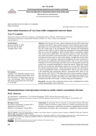
This document discusses innovations in the structural design of roller compacted concrete (RCC) dams to reduce cement consumption and expand their use on non-rock foundations. It analyzes the static and seismic stress-strain states of symmetrical RCC dams with very lean concrete cores. It finds that for rock and dense sandy-gravel foundations, symmetrical RCC dams with slopes of 0.5-0.7 and outer zones of conventional concrete and central zones of cement-strengthened rockfill are the most economical option. These dams can be built up to 200m high on rock foundations and up to 100m high on dense sandy gravel foundations. They have greater seismic resistance and technical/economic efficiency than conventional RCC dams.

Recommended
Recommended
More Related Content
What's hot
What's hot (17)
Similar to Lean RCC Dams Innovation for Foundation Types
Similar to Lean RCC Dams Innovation for Foundation Types (20)
More from Yury Lyapichev
More from Yury Lyapichev (20)
Recently uploaded
Recently uploaded (20)
Lean RCC Dams Innovation for Foundation Types
- 1. 2021. 17(3). 248–260 СТРОИТЕЛЬНАЯ МЕХАНИКА ИНЖЕНЕРНЫХ КОНСТРУКЦИЙ И СООРУЖЕНИЙ STRUCTURAL MECHANICS OF ENGINEERING CONSTRUCTIONS AND BUILDINGS ISSN 1815-5235 (Print), 2587-8700 (Online) HTTP://JOURNALS.RUDN.RU/STRUCTURAL-MECHANICS 248 ANALYSIS AND DESIGN OF BUILDING STRUCTURES DOI 10.22363/1815-5235-2021-17-3-248-260 UDC 627:624.01 RESEARCH ARTICLE / НАУЧНАЯ СТАТЬЯ Innovation structures of very lean roller compacted concrete dams Yury P. Lyapichev Hydroproject Institute (Joint Stock Company), 2 Volokolamskoe Shosse, Moscow, 125993, Russian Federation International Commission on Large Dams (ICOLD), 61 Kleber Ave., Paris, 75016, French Republic lyapichev@mail.ru Article history Received: March 16, 2021 Revised: May 30, 2021 Accepted: June 5, 2021 Abstract. Over the past 20 years, rolled compacted concrete (RCC) dams have continued to be built in many countries because of their technical and economic advantages over conventional dams of vibrating concrete and embankment dams. The aim of this study is the development of new structural and technological solutions in RCC dams in order to reduce the consumption of cement and expand their use on non-rock foundations, which will allow them to successfully compete with concrete face rockfill dams. The numerical analyses of static and seismic stress-strain state (SST) of gravitational dams in roller compacted very lean con- crete dams have been made, as well as their stability, strength and cost have been assessed. For rock and dense sandy-gravel foundations the most economical is the concrete face rockfill dam and symmetrical RCC dam of very lean concrete with bases (0.5–0.7) of both slopes and outer zones of conventional concrete and central zone of rockfill strengthened by cement-ash mortar. Taking into account that the cost of diversion and spillway tunnels for very lean RCC dam will be less and the construction period – shorter than for the concrete face rockfill dam, it can be concluded that variant of symmetrical RCC dam of very lean concrete is the technically and economically effective. Symmetrical RCC dams of very lean concrete with 1V/(0.5–0.7)H slopes have more seismic resistance and tech- nical and economic efficiency as compared with conventional gravitational RCC dams and other types of dams. These dams up to 200 m high can be built on rock foundations and up to 100 m high – on dense sandy gravel foundations. Keywords: very lean roller compacted concrete, dams, strengthened by cement rockfill, geomembrane, stress-strain state For citation Lyapichev Yu.P. Innovation structures of very lean roller compacted concrete dams. Struc- tural Mechanics of Engineering Construc- tions and Buildings. 2021;17(3):248–260. http://dx.doi.org/10.22363/1815-5235-2021- 17-3-248-260 Инновационные конструкции плотин из особо тощего укатанного бетона Ю.П. Ляпичев1 АО «Институт “Гидропроект”», Российская Федерация, 125993, Москва, Волоколамское шоссе, д. 2 Международная комиссия по большим плотинам (ICOLD), Французская Республика, 75016, Париж, Avenue Kleber, 612 lyapichev@mail.ru История статьи Поступила в редакцию: 16 марта 2021 г. Доработана: 30 мая 2021 г. Принята к публикации: 5 июня 2021 г. Аннотация. В последние 20 лет плотины из укатанного бетона (УБ) про- должают строить во многих странах ввиду их технико-экономических пре- имуществ по сравнению с обычными плотинами из вибрированного бетона и грунтовыми плотинами. Цель исследования – разработать новые конструк- Yury P. Lyapichev, expert for foreign projects, member of the ICOLD, Doctor of Technical Sciences, Professor; eLIBRARY SPIN-code: 3096-6362, ORCID: https://orcid.org/0000- 0003-3750-3165 Ляпичев Юрий Петрович, эксперт по зарубежным проектам, член Комитета СИГБ по компьютерным аспектам расчета и проектирования пло- тин, доктор технических наук, профессор; eLIBRARY SPIN-код: 3096-6362, ORCID: https://orcid.org/0000- 0003-3750-3165 © Lyapichev Yu.P., 2021 This work is licensed under a Creative Commons Attribution 4.0 International License https://creativecommons.org/licenses/by/4.0/
- 2. Ляпичев Ю.П. Строительная механика инженерных конструкций и сооружений. 2021. Т. 17. № 3. С. 248–260 РАСЧЕТ И ПРОЕКТИРОВАНИЕ СТРОИТЕЛЬНЫХ КОНСТРУКЦИЙ 249 тивно-технологические решения в плотинах из УБ с целью снижения рас- хода цемента и расширения их применения на нескальных основаниях, что позволит им успешно конкурировать с грунтовыми плотинами с экранами из железобетона. Выполнены численные расчеты статического и сейсмиче- ского напряженно-деформированного состояния гравитационных плотин из особо тощего укатанного бетона, а также оценка их устойчивости, прочно- сти и стоимости. Наиболее экономичными для скального и плотного песчано- гравелистого оснований являются грунтовая плотина с экраном из железо- бетона и симметричная плотина с заложением откосов 0,5–0,7 с наружны- ми зонами из особо тощего укатанного бетона и центральной зоной из кам- ня, упрочненного цементно-зольным раствором. Учитывая, что стоимость отводящих и водосбросных туннелей при плотине из особо тощего укатан- ного бетона будет меньше, а срок строительства – короче, чем при грунто- вой плотине с экраном из железобетона, можно сделать вывод о технико- экономической эффективности варианта плотины из особо тощего укатан- ного бетона. Плотины симметричного профиля из особо тощего укатанного бетона с заложением обоих откосов 0,5–0,7 обладают более высокой сей- смостойкостью и технико-экономической эффективностью по сравнению с обычными гравитационными плотинами из УБ и другими видами плотин. Плотины данного типа высотой до 200 м можно строить на скальных осно- ваниях, а высотой до 100 м – на плотных песчано-гравелистых основаниях. Ключевые слова: плотины, особо тощий укатанный бетон, упрочненный цементом камень, геомембрана, напряженно-деформированное состояние, сейсмостойкост Для цитирования Ляпичев Ю.П. Инновационные кон- струкции плотин из особо тощего ука- танного бетона // Строительная механи- ка инженерных конструкций и соору- жений. 2021. Т. 17. № 3. С. 248–260. http://dx.doi.org/10.22363/1815-5235-2021- 17-3-248-260 Introduction In most countries of the world when designing gravity dams from conventional and RCC use two main conditions of strength (M. Levy and O. Hoffman), written in the following form respectively: σ(B) – γwH > σt; (1) dσ(B) / dat > 0, (2) where σ(B) – total vertical normal stress (compression with sign “–”) in point B (at the end of open crack, Figure 1, b; γw – density of water; H – head; σt – tensile strength of RCC in seams; at – crack length in upstream face. In crack (opened “cold” seam) there is complete uplift water pressure and shear resistance in RCC seam is absent. The first condition (1) means that the effective normal stress in point B does not exceed the tensile strength of RCC in seams (approximately equal to cohesion) and then the AB crack does not develop (seam opening does not occur). Equation (1) requires knowledge of stresses σ(B), which is not determined by the equilibrium equations alone. According to the theory of eccentric compression, which is not applicable, especially for the contact sec- tion, the distribution of total vertical stresses will be linear from point B to the downstream face, i.e. in closed (work) zone of RCC seam (Figure 1, b). For this RCC dam profile and the operating loads, the stress in point B depends on coefficient α of relative depth of crack propagation (α = AB / AC). With increase of α coefficient the moment from dam own weight relatively to point B increases, which leads to decrease of normal stress, while uplift water pressure increases, which leads to increase of normal stress. The balance between these two counte- ractions is expressed by Hoffman condition (2). If Hoffman condition (2) is not held and Levy condition (3–1) is held, then this means crack spreading or seam opening. As α coefficient increases, the tension in point B de- creases, which leads to decrease of normal stresses. There may be value of α coefficient greater than given αo for which Levy condition will be held. If both conditions (1) and (2) are not held, this means unstable crack propagation or opening of RCC seam with increase of α coefficient effective tension in point B increases. Dam failure is inevitable if Hoffman condition (2) is not held for any value of α coefficient greater than αo. The fulfillment of both conditions in designing of gravity dam of height of 100 m of conventional concrete with vertical upstream face for average values of shear strength of the rock foundation (excluding seismic loads) leads to adoption of base of downstream slope of about 0.8.
- 3. Lyapichev Yu.P. Structural Mechanics of Engineering Constructions and Buildings. 2021;17(3):248–260 250 ANALYSIS AND DESIGN OF BUILDING STRUCTURES a b Figure 1. Strength condition for crack appearance (joint opening) in RCC dam а b Figure 2. Vertical stresses, MPa, in foundation of gravity (a) and symmetrical (b) RCC dam (h = l00 m) Crack zone Monolithic zone Open crack Uplift diagram Diagram of normal stresses sigm(y) in monolithic zone sigm(y) (tension)
- 4. Ляпичев Ю.П. Строительная механика инженерных конструкций и сооружений. 2021. Т. 17. № 3. С. 248–260 РАСЧЕТ И ПРОЕКТИРОВАНИЕ СТРОИТЕЛЬНЫХ КОНСТРУКЦИЙ 251 Further are the given results of calculations of stability and contact stress in symmetrical dam from very lean RCC with base of downstream slope of 0.7 and in conventional gravity dam of 100 m high (on rock foun- dation) with lower face of 0.8. Figure 2, b presents results of calculations of boundary vertical contact stresses (in MPa), dependence of angle of deviation of resultant of all forces in dam foundation from the vertical and margin of safety in-plane shear (SF) in dam foundation from degree of residual uplift water pressure and due to drainage operation. For comparison, Figure 2, a shows the same results of calculations and dependences for gravity dam of the same height (100 m) from conventional concrete (density 2.4 t/m2 ) with vertical upstream face. In rock foun- dation of both dam, equal shear strength is adopted (internal friction angle φ = 30o , cohesion C = 0.3 MPa), which correspond to the criteria of Hoek for rock granite-gneisses of average weathered with crack spacing of 0.5 m. Another large difference between both dams concerns shear stresses in the contact section: in symmetrical dam from RCC the average shear stresses are much lower. than in gravity dam (0.36 vs 0.63 MPa). The angle of deviation θ of resultant of all forces in foundation from the vertical, depending on uplift pressure u in symmet- rical dam, varied from 14 to 22o whereas in gravity dam from 27 to 42o (Figure 2, a). In 1992, P. Londe, President of ICOLD proposed an idea of solid embankment [1] from very lean RCC with a cement consumption of 50 kg/m3 in dam of symmetrical profile h = 100 m with the base of both slopes of 0.7 on rock foundation. This idea was supported by some specialists [2]. The water tightness of dam was provi- ded by reinforced concrete face on upstream slope (Figure 3). Figure 3. Symmetrical h = 100 m of the very lean RCC dam with reinforced concrete face Further development of this idea led to development in 1998 [3–4] of project of symmetrical dam h = 100 m with base of both slopes of 0.5, external zones of RCC of 3rd type according to RCC classification [4] (cement consumption 70–80, fly ash 100–120 kg/m3 ) with width equal to (3 + 0.1H), (where H is reservoir head, m) and inner zone of rockfill, enriched or hardened with cement-ash mortar (REC) or RCC-0 (Figure 4). Advantages of symmetrical dams of very lean RCC (Figure 3) and rockfill enriched or hardened with cement-ash mortar (Fi- gure 4) compared to conventional gravity dams from RCC are following: 1) reduction of stresses in dam body and its foundation; 2) low cost of very lean RCC and rockfill enriched with cement; 3) greater seismic resistance than that of gravity dams from RCC; 4) the possibility of construction on semi-rock foundations; 5) treatment of horizontal seams is not required; 6) small number of deformation joints with their large spacing (30–40 m); 7) drainage of dam foundation occurs due to permeability of lower layer of the inner zone REC or RCC-0, seepage uplift pressure in foundation due to grout curtain from the gallery will be small.
- 5. Lyapichev Yu.P. Structural Mechanics of Engineering Constructions and Buildings. 2021;17(3):248–260 252 ANALYSIS AND DESIGN OF BUILDING STRUCTURES Water impermeability of upstream face is provided by geomembrane CARPI (Switzerland) – a two-layer film made of PVC and drainage of 3 mm thick geotextile (Figure 4). Installation of strips of film with 2.1 m width is carried out independently and in parallel with placement of RCC by platforms fixed on dam crest and descending along upstream face along the rails. The lower end of film is anchored in concrete apron in founda- tion of upstream face and upper end is anchored in dam crest on steel plates and bolts (Figure 5). The impermea- bility of film joints and fasteners is provided by rubber seals and smearing of joints with epoxy glue. Figure 4. Symmetrical dam with outer zones of RCC (type 3) from 30 cm thick layers and inner zones of rockfill enriched with cement-ash mortar (REC or RCC-0) from 60 cm thick layers Figure 5. Geomembrane CARPI of upstream face of RCC dams Typical cross sections: Contour slab-apron (f): Vertical anchorage and drain-age of geomembrane (c): × × × ×
- 6. Ляпичев Ю.П. Строительная механика инженерных конструкций и сооружений. 2021. Т. 17. № 3. С. 248–260 РАСЧЕТ И ПРОЕКТИРОВАНИЕ СТРОИТЕЛЬНЫХ КОНСТРУКЦИЙ 253 The CARPI geomembrane is installed and successfully operated on 37 dams from the RCC [5–8]. It is characterized by high reliability from punctures, water resistance, high drainage capacity and is recommen- ded for use in these dams in ICOLD Bulletin 135 (2010) [9]. Methods Methodology of numerical modeling of seismic resistance of dam taking into account the possibility of opening of technological seams When numerically assessing of seismic resistance of system “dam – foundation – reservoir” system of equations of motion is to be solved: [K] {U} + [C] {V} + [M] {W} = {R(t)}, (3) where [K], [C], [M] – matrix of stiffness, damping and masses of calculation area; {U}, {V}, {W} – vectors of relative displacements, velocity and acceleration in fixed points of calculation area; {R(t)} – vector of variable dynamic actions. Solution of system of equations (3) is made according to method used in analyses of dams from conven- tional concrete. These analyses did not take into account the influence of gravitational waves and simplified the boundary conditions between reservoir and dam and reservoir and dam foundation at these boundaries the condition of equality of movements normal to these boundaries, both for solid body (dam, foundation) and water, is fulfilled. Transmission of tangential stresses at these boundaries is taken into account, which simplifies the task by abandoning introduction of contact elements. To describe behavior of RCC an elastic plastic (with hardening) model of conventional concrete used in seismic analyses of concrete dams was used, in which shear parameters of RCC seams were adopted (internal friction angle φ = 45°, cohesion C, tensile strength across seam p = C). Description of RCC deformability in the model is made by piecewise smooth loading surface separating the area of elastic operation of RCC in stress space from the stress change area in which plastic deformations are developing. Introduction of loading surface defines the concepts of loading, unloading and neutral loading. Complete deformations consist of viscoelastic and plastic deformations. In analysis of viscoelastic and plastic deformations the flow law associated with loading function from Mises maximum principle is used: dεvp ij = ∑ 𝑑λ𝑡∂fr / ∂σij. (4) For system of determining parameters tangent and normal stresses on maximum shear site are accepted τv = (σ1 – σ2) / 2; σv = (σ1 + σ2) / 2. (5) Hardening parameters are shear and volumetric pseudoplastic deformations on maximum shear site 1 2 1 2 γ = ε ε / 2; ( ) ( θ ε ε / 2. ) vp vp vp vp vp vp v v (6) Loading functions of the model are formulated on the basis of analysis of available experimental data of RCC as follows τv = σv – p. (7) Equation (7) reflects the destruction of RCC with predominance of tensile stresses, equation (6) – behavior of RCC in case of its destruction from compressive stresses. The RCC model allows to reproduce in analyses the appearance of horizontal cracks in dam (opening of RCC seams) and in dam foundation – arbitrary cracks and subsequent work of RCC in crack zone only for com- pression.
- 7. Lyapichev Yu.P. Structural Mechanics of Engineering Constructions and Buildings. 2021;17(3):248–260 254 ANALYSIS AND DESIGN OF BUILDING STRUCTURES Results of analyses and its discussion Analyses of stability, strength and cost of RCC dams Below are given results of analyses of stability and strength of 4 types of dams h = 100 m: gravity dam from RCC-3rd type (Figure 6), rockfill dam with reinforced concrete face, dam from very lean RCC (Figure 3) and dam from RCC and rockfill enriched with cement-ash mortar (Figure 4). The rock foundation (angle of inner friction = 45o , cohesion C = 1 MPa) was considered in all variants, non-rock foundation = 30o , C = 0.3 MPa) in variants 2–4. These analyses took into account the earthquake intensity on the MSK-81 scale of 8 grade (acceleration 0.2g). Variant 1 (Figure 6): gravity RCC dam with downstream face with the base of 0.8 and upstream face with the base of 0.1, crest width of dam – 8 m. Uplift water pressure in dam foundation is taken into account its de- crease in drainage by 35%. Parameters of shear strength in RCC seams: = 45o , C = 2 MPa. Seismic resistance of the dam was determined by the pseudostatic method [28]. Variant 2: rockfill dam with with reinforced concrete face, the base of upstream slope 1.4, the base of downstream – 1.5, crest width of dam – 8 m. The shear strength of rockfill: = 45o , С = 0. Seismic resistance of both slopes was determined by the pseudostatic method of Terzaghi – VNIIG. Variant 3 (Figure 4): symmetrical dam with outer zones from RCC-3 and inner zone from rockfill, en- riched with cement-ash mortar with base of both slopes 0.5 with upstream face of geomembrane CARPI. Para- meters of shear strength in RCC seams: = 45o , C = 0.5 MPa, in rockfill, enriched with cement-ash mortar: = 45o , C = 0.1 MPa. Uplift water pressure in drainage is decreased by 40%. Variant 4 (Figure 3): symmetrical dam from very lean RCC with face of reinforced concrete (base of both slopes 0.7). Parameters of shear strength in RCC seams: = 45o , C = 0.5 MPa. Uplift water pressure in drainage is decreased by 40%. Calculations of cost of all dam variants (for running meter) were made by unit prices (for 1 м3 ) in 1995, given in [10]. As criteria for the stability of RCC dams the safety factor for in-plane shear (SF) in dam foundation or for round-cylindrical sliding (in variant 2) and tgØ (Ø – angle of deviation of resultant of all forces in dam foun- dation from the vertical), normal vertical stresses σy: tensile (+) and compressive (–) were used. Results of ana- lyses of seismic resistance and cost of 1 running meter of dam is given in Table. 3.1 and 3.2 for both dam foun- dations [10]. As can be seen from Tables 1 and 2 the most economical for rock and sand-gravel foundations will be: variant 2 (rockfill dam with reinforced concrete face) and variant 4 (symmetrical dam with outer zones of RCC-3 and inner zone of rockfill enriched or hardened with cement-ash mortar). Figure 6. Gravity dam from RCC-3 Spillway sill in spillway dam section Spillway face in spillway dam section Gallery Drainage curtain Normal operation level Geomembrane CARPI RCC type Grout curtain 0.0 m 100.0 m 8 m
- 8. Ляпичев Ю.П. Строительная механика инженерных конструкций и сооружений. 2021. Т. 17. № 3. С. 248–260 РАСЧЕТ И ПРОЕКТИРОВАНИЕ СТРОИТЕЛЬНЫХ КОНСТРУКЦИЙ 255 Table 1 Results of analyses of stability, stresses and cost of dams on rock foundation Cost, thous. doll. per running m Dam variant SF (tgØ) whithout seism SF (tgØ) with seism y, MPa, whithout seism y, MPa, with seism 140 1 3.0 (0.7) 1.85 (1.16) <0 +1.2 91 2 1.4 1.2 – – 115 3 4.3 (0.23) in D-S 3.3 (0.34) in U-S 2.7 (0.43) in D-S 2.1 (0.58) in U-S –1.03 in D-S –1.56 in U-S –0.74 in D-S –1.78 in U-S 155 4 4.8 (0.21) in D-S 3.7 (0.29) in U-S 2.9 (0.32) in D-S 2.3 (0.48) in U-S <0 <0 Note: D-S – downstream slope; U-S – upstream slope or face. Table 2 Results of analyses of stability, stresses and cost of dams on soil foundation Cost, thous. doll. per running m Dam variant SF (tgØ) whithout seism SF (tgØ) with seism y(–), MPa, whithout seism y(–), MPa, with seism 91 2 1.4 1.2 – – 115 3 2.8 (0.32) in D-S 2.1 (0.39) in U-S 1.51 (0.56) in D-S 1.16 (0.82) in U-S –1.12 in D-S –1.67 in U-S –0.8 in D-S –1.9 in U-S 155 4 3.0 (0.28) in D-S 2.3 (0.42) in U-S 1.57 (0.53) in D-S 1.20 (0.8) in U-S –0.9 in D-S –1.4 in U-S –0.6 in D-S –1.8 in U-S Note: D-S – downstream slope; U-S – upstream slope or face. Given that the cost of diversion and spillway tunnels in variants 3 and 4 will be much less, and the con- struction time will be shorter than in variant 2 approximately by half a year or a year, it can be concluded about cost effectiveness of variants 3 and 4 of RCC dams. Stability and strength of RCC dams for static and seismic loads Tables 3 and 4 show stability and safety factors for in-plane shear on foundation of conventional gravity dam from RCC-3 (h = 100 m) with vertical upstream face and downstream face with bases 0.7; 0.8; 0.9 and symmetrical RCC-3 and RCC-0 (h = 100 m) with bases of both slopes 0.5 and 0.7. Both dams are located on rock (φ = 40o , С = 0.2 MPa) and dense sandy-gravel (φ = 35o , С = 0) foun- dations. In analyses the uplift water pressure along the axis of grout curtain (on rock foundation) or wall curtain (on soil foundation) in 40% of water pressure was taken. Analyses of seismic stability of the dam were carried out according to the linear-spectral theory (LST). Table 3 Coefficients of stability factor on shear of gravity dam from RCC-3 (h = 100 m) Type of foundation Coefficients of stability factor of dam on shear (static/seismic) for bases of downstream slope 0.7 0.8 0.9 Rock 1.91/1.47 2.14/1.60 2.37/1.73 Sandy gravel 1.33/1.02 1.50/1.12 1.66/1.21 Table 4 Coefficients of stability factor on shear of symmetrical dam from RCC (h = 100 m) for various foundations Type of foundation Coefficients of stability factor of dam on shear (static/seismic) for bases of both slopes 0.5 0.7 Rock 3.15/2.21 4.27/2.74 Sandy gravel 2.20/1.55 2.98/1.92 Comparison of Tables 3 and 4 with normative stability coefficients of concrete dams of class I, equal in static and seismic cases 1.32 and 1.18 respectively, shows that seismic resistance of gravity dam (bases upstream slope of 0.7–0.8) is insufficient on sandy-gravel foundation. In this case, it is necessary to change the usual dam profile to symmetrical one of RCC-0 and RCC-3 with bases of both slopes of 0.5–0.7 (Figures 3 and 4).
- 9. Lyapichev Yu.P. Structural Mechanics of Engineering Constructions and Buildings. 2021;17(3):248–260 256 ANALYSIS AND DESIGN OF BUILDING STRUCTURES Analyses of 100 m high symmetrical dam (from RCC-3 and RCC-0) on action of powerfull earthquake accelerograms In these analyses the same parameters of shear strength of RCC-3 and RCC-0 were used as in previous analyses of seismic resistance within LST framework and parameters of deformability of rock foundation (E = 10000 MPa and υ = 0.2). Symmetrical dam analyses of RCC-3 and RCC-0 for 100 m high dam with bases of both slopes of 0.5 for action of the earthquake accelerogram with horizontal acceleration of 0.2g and vertical one of 0.14g showed that for magnitude 8 of earthquake the dam works elastically and quite reliably and its movements completely fade by the end of earthquake. Figure 7 shows the mesh of finite elements (FE) of dam with one short crack (seam opening) in foundation of upper zone RCC-3. With horizontal acceleration of 0.4g and vertical one of 0.28g, the dam reaction in its foundation is elastic with complete damping of oscillations, in upper part the dam reaction is elasto-plastic. The picture of opening seams of RCC (Figure 8) shows that in dam foundation the depth of seams opening from reservoir side reaches the middle of dam profile and from downstream side reaches its quarter. Taking into ac- count availability of CARPI membrane on upstream slope the uplift water pressure in opened seams of RCC is excluded and the seismic resistance of dam is ensured. Figure 7. Mesh of FE and joint opening (bold line) in base of upstream zone of the RCC-3 for earthquake of magnitude 8 (Ahoriz = 0.2g, Avert = 0.14g) Figure 8. Mesh of FE and joint opening (bold line) in base of upstream zone of the RCC-3 for earthquake of magnitude 9 (Ahoriz = 0.4g, Avert = 0.28g) Thus, symmetrical dam of h = 100 m (bases of both slopes of 0.5) has sufficient factor of seismic re- sistance during earthquake of magnitude 8 and 9, which indicates expediency of its consideration in dam projects in seismic areas of Russia, CIS countries and foreign countries. At present the optimization of structures and technologies of construction of traditional RCC dams [11–23] and competing with these dams rockfill dams with reinforced concrete faces [24–27] continues. Examples of new symmetrical dams from very lean RCC Cindere 107 m high dam in Turkey In 2005 Cindere dam was built in Turkey, the highest (107 m) and largest (the volume of RCC is 1.5 mil- lion m3 , the total volume of concrete is 1.7 million m3 ) dam of this type. Feature of dam layout is arrangement on its downstream slope the operated spillway and water intake of hydropower power plant (Figure 9). The spillway central section of dam has base of downstream slope increased to 0.89 for favorable interface with the apron slab. The spillway with 4 holes of 10 m wide and 12.5 m high, overlapped by segment gates is designed to pass 3620 m3 /sec. The profile of Cindere dam is symmetrical with base of both slope of 0.7. Figure 10 show the sta- ges of its construction given in [20]. The dam is located on semi-rock foundation of aspid shales with dry com- pressive strength (5–24) MPa and deformation module (1–7)104 MPa. In the dam particularly rigid RCC-1 was used with consumption of cement 50 and fly ash of 20 kg/m3 , thickness of layers of RCC – 25 cm. Watertight- ness of upstream slope was provided by precast concrete panels with PVC film fixed on them, which cannot be considered successful due to danger of its punctures during mounting. The dam stability to shear in its foundation and seams in RCC was ensured for maximum horizontal ac- celeration of 0.4g. Compressive stresses were provided on upstream slope of the dam and its foundation, ensu-
- 10. Ляпичев Ю.П. Строительная механика инженерных конструкций и сооружений. 2021. Т. 17. № 3. С. 248–260 РАСЧЕТ И ПРОЕКТИРОВАНИЕ СТРОИТЕЛЬНЫХ КОНСТРУКЦИЙ 257 ring that there is no opening of contact seam in foundation and seams of RCC. Due to the high seismicity RCC seams on the upstream side were treated with layer of cement mortar 25 mm thick to depth of 13 m in the bottom of upstream slope and 5 m in dam crest, which ensured high cohesion between RCC cold layers. The construc- tion period of the dam was 34 months, which corresponds to the average monthly intensity of placement of RCC of 50 thousand m3 . At present 3 project of such dams are being considered in Turkey. Figure 9. Plan of Cindere hydroscheme with RCC-1 dam, spillway and hydropower plant building (dam crest length – 280 m) [20] a b Figure 10. Top (а) and upstream (b) views of Cindere dam [20] Ituango dam of height 180 m in Colombia In 1999 energy company ISAGEN (Medellín) invited the author of article to conduct expertise of the fea- sibility study of the dam project. In the feasibility study rockfill dam with reinforced concrete face was adopted as main variant, which was used in many dam projects in Colombia. Instead of this dam variant by our recommendation was developed symmetrical gravity dam from RCC-2 with bases of both slopes of 0.7, height of 180 m, length along the dam crest of 450 m, RCC volume of 2.4 mil- lion m3 with surface spillway (Figure 11), which allows to abandon spillway tunnels, significantly accelerates the total dam construction time and reduces its cost [3]. The dam is able to resist earthquake of 9 magnitude without opening of RCC seams and dynamic loads when flood of 21.000 m3 /sec passes through operating spill- way with 21.7 m head (with smooth spillway face and jet throw in downstream zone). The head of spillway was made of reinforced concrete, non-overflow part of dam crest has curved surface to reduce stress concentrations during the earthquake. Composition of RCC-2 (per 1 m3 ): cement 100–120 kg, crushed stone – 1250 kg, pebble gravel – 1000 kg. Due to wide dam profile the treatment of cold seams of RCC with cement mortar is assumed only in pressure and upper zones of the dam. The dam profile includes 33 m high upstream coffer dam with grout gallery on its crest, which will accelerate the dam construction.
- 11. Lyapichev Yu.P. Structural Mechanics of Engineering Constructions and Buildings. 2021;17(3):248–260 258 ANALYSIS AND DESIGN OF BUILDING STRUCTURES Figure 11. Profile of spillway section of RCC-2 Ituango dam, H = 180 m Yumaguzinskaya dam from very lean RCC (65 m high, Russia, project variant) When designing this hydraulic system we developed variant of dam 65 m high and 600 m length from very lean RCC on soft foundation. Technical and economic advantages of this dam variant in comparison with accepted variant of rockfill dam: 1) arrangement of regulated spillway in channel part of dam, which allows to abandon bank side spillway; 2) allowing overflow of peak of catastrophic flood over dam crest, which reduces level of Surcharged Reservoir Level (SRL) and flooding of downstream area; 3) lower cost and construction time. Analyses of stability and strength of spillway dam (bases of both 0.7) in channel of gravel-pebble deposits for static and seismic loads (7 grade) showed high stability and strength of dam and its foundation with uniform diagram of vertical stresses in foundation. Figures 12 and 13 show symmetrical profiles of spillway and non- overflow dam sections from very lean RCC. In foundation of both sections from upstream gallery were made trench walls-curtains (15 m deep in channel and up to 70 m on right bank). Figure 12. Spillway section of Yumaguzinskaya from very lean RCC: 1 – watertight reomembrane; 2 – channel deposits; 3 – trench wall-curtain; 4, 5 – semi-rock deposits; ФПУ – surcharged reservoir level; НПУ – normal reservoir level; РПУ – rated reservoir level; RCC – RCC type 2; REC – rockfill, strengthened by cement-ash mortar; CVC – conventional vibrating concrete
- 12. Ляпичев Ю.П. Строительная механика инженерных конструкций и сооружений. 2021. Т. 17. № 3. С. 248–260 РАСЧЕТ И ПРОЕКТИРОВАНИЕ СТРОИТЕЛЬНЫХ КОНСТРУКЦИЙ 259 Figure 13. Non-overflow section of Yumaguzinskaya dam from very lean RCC: 1 – CARPI membrane; 2 – precast concrete blocks; 3 – gravely sands; 4 – trench cut-off wall; 5 – drainage holes; 6 – bed rock; CVC – conventional concrete; RCC-1 – RCC type 1; REC – rockfill, strengthened by cement-ash mortar Conclusion Dams of symmetrical profile of very lean RCC with bases of both slopes 0.5–0.7 have higher seismic re- sistance and technical and economic efficiency compared to conventional gravity dams from RC C and other types of dams. These dams up to 200 m high can be built on rock foundations and up to 100 m high on dense sandy- gravel foundations. The possibility of building these dams in seismically active areas of Russia, CIS countries, Latin America and Asia, as well as in Russian dam projects abroad should be considered. References 1. Londe P. The faced symmetrical hardfill dam: a new concept for RCC. Intern. Water Power and Dam Construc- tion. 1992:19–24. 2. Jinsheng J., Cuiying Z., Zhenkun D. Cemented material dams and their application. Hydropower and Dams. 2015; 22(6):64–67. 3. Lyapichev Yu. Presas de concreto compactado con rodillo (CCR) y presas mixtas de CCR y escollera (Aspectos de Diseño y Construccion). Seminar sobre presas de CCR. Medellin, Colombia: Compania ISAGEN; 1998. p. 102. 4. Lyapichev Yu.P. Design, construction and behavior of modern high dams. Part 1. Dams made of rolled concrete. Saarbrücken: Palmarium Academic Publish; 2013. (In Russ.) 5. Kalpakci V., Bonab A.T., Ozkan M.Y. Experimental evaluation of geomembrane/geotextile interface as base iso- lating system. Geosynthetics Intern. 2018;25(1):1–11. https://doi.org/10.1680/jgein.17.00025 6. Yang P., Xue S.B., Song L., Zhu X.W. Numerical simulation of geomembrane wrinkle formation. Geotextiles and Geomembranes. 2017;45(6):697–701. https://doi.org/10.1016/j.geotexmem.2017.08.001 7. Giroud J. Leakage control by geomembranes. Soils and Rocks. 2016;3:213–235. 8. Moutafis N., Thanopoulos Y. Geomembrane faced hardfill dam. Hydro 2015. Bordeaux, France; 2015. 9. ICOLD Bulletin 135. Geomembrane sealing systems for dams. 2010. 10. Blinder S., Toniatti N. RCC and CFR Dams. Cost Comparision, Intern. Symposium on RCC Dams, Santander, Spain. 1995:71–83. 11. Cervera M., Oliver J., Prato T. Simulation of construction of RCC dams. Part II: stress and damage. Journal of Structural Engineering. 2000;126(9):1062–1069. https://doi.org/10.1061/(asce) 0733-9445(2000)126:9(1062) 12. Zhang X., Li S., Li Y., Ge Y., Li H. Effect of superficial insulation on RCC dams in cold regions. Advances in Engineering Software. 2011;42:939–943. https://doi.org/10.1016/j.advengsoft. 2011.06.004 13. Tamagava S. Toubetsu dam: example of innovative CSG technology. Hydropower and Dams. 2012;19(3):64–67. 14. Fujisawa T., Sasaki T. Development of the trapezoidal CSG dam. Hydropower and Dams. 2012;19(3):58–63.
- 13. Lyapichev Yu.P. Structural Mechanics of Engineering Constructions and Buildings. 2021;17(3):248–260 260 ANALYSIS AND DESIGN OF BUILDING STRUCTURES 15. Kuzmanovic V., Savic L., Mladenovic N. Computation of thermal-stresses and contraction joint distance of RCC Dams. Journal of Thermal Stresses. 2013;36(2):112–134. https://doi.org/10.1080/ 01495739.2013.764795 16. Mohamed I. Investigating the possibility of constructing low cost RCC dam. Alexandria Engineering Journal. 2014;53(1):131–142. https://doi.org/10.1016/j.aej.2013.11.009 17. Gu Q., Yu C., Lin P., Ling X., Tang L., Huang S. Performance assessment of a concrete gravity dam at Shenwo reservoir of China using deterministic and probabilistic methods. International Journal of Structural Stability & Dynamics. 2014;14(05):1440002. https://doi.org/10.1142/S0219455414400021 18. Du C.B., Wu S.Y., Zhang S.R. Full-scale dynamic simulation and visualization for structure safety and schedule coupling of RCC gravity dams. 2017 International Conference on Smart Grid and Electrical Automation (ICSGEA). 2017;1:481–487. https://doi.org/10.1109/ICSGEA.2017.96 19. Wanga L., Yang H.Q., Zhou S.H., Chen E., Tang S.W. Mechanical properties, long-term hydration heat, shink- age behavior and crack resistance of dam concrete designed with low heat Portland (LHP) cement and fly ash. Construction and Building Materials. 2018;187:1073–1091. https://doi.org/10.1016/j.conbuildmat.2018.08.056 20. Batmaz S. Cindere dam – 107 m high RCC dam (RCHD). Proceedings of IV International Symposium on RCC Dams, Madrid, Spain. 2003;1:121–126. 21. Bayagoob K., Bamaga S. Construction of roller compacted concrete dams in hot arid regions. Materials. 2019;12(19):3064. https://doi.org/10.3390/ma12193064 22. ICOLD Bulletin 177. Roller compacted concrete dams. 2020. 23. Aniskin N.A., Shajtanov A.M. Low-cement concrete dams: construction, structures and innovations. Vestnik MGSU. 2019;15(7):1018–1029. (In Russ.) https://doi.org/10.22227/1997-0935.2020.7.1018-1029 24. Sainov M.P., Shigarov A.Yu., Yasafova S.A. Reinforcement impact on the stress-deformation state of concrete faced rockfill dam. Vestnik MGSU. 2019;14(3):347–355. (In Russ.) https://doi.org/10.22227/1997-0935.2019.3.347-355. 25. Hu K., Chen J., Wang D. Shear stress analysis and crack prevention measures for a concrete face rockfill dam, advanced construction of a first-stage face slab, and a first-stage face slab in advanced reservoir water storage. Advances in Civil Engineering. 2018;2018:2951962. https://doi.org/10.1155/2018/2951962 26. Sukkarak R., Pramthawee P., Jongpradist P., Kongkitkul W., Jamsawang P. Deformation analysis of high CFRD considering the scaling effects. Geomechanics and Engineering. 2018;14(3):211–224. https://doi.org/10.12989/gae.2018.14.3.211 27. Glagovsky V.B., Radchenko V.G. New trends in the construction of ground dams. Gidrotekhnicheskoe Stroitel'stvo. 2013;(1):2–8. (In Russ.) 28. SNiP. 33-03. Hydraulic structures in seismic regions. Moscow: State Building Committee of Russia; 2003. (In Russ.)