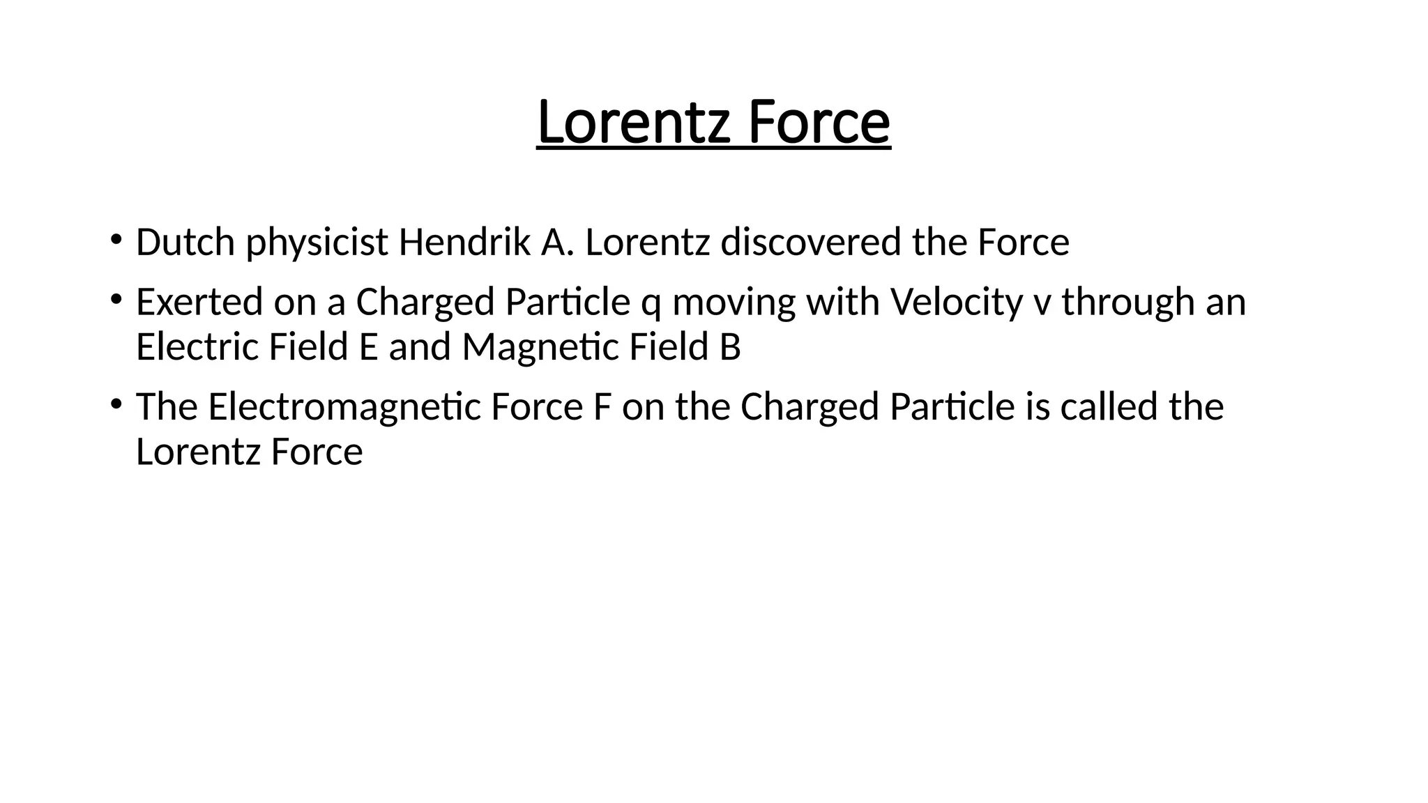
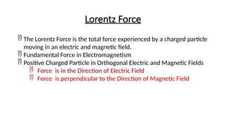
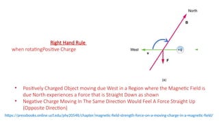
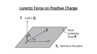
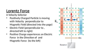
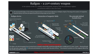
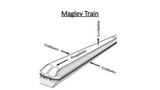
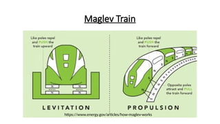
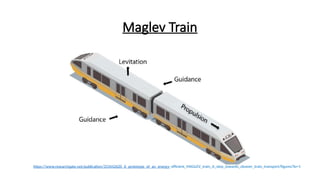
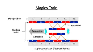
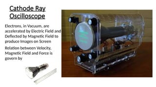
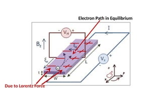
Lorentz Force
• Dutch physicist Hendrik A. Lorentz discovered the Force
• Exerted on a Charged Particle q moving with Velocity v through an
Electric Field E and Magnetic Field B
• The Electromagnetic Force F on the Charged Particle is called the
Lorentz Force
Lorentz Force
 The Lorentz Force is the total force experienced by a charged particle
moving in an electric and magnetic field.
 Fundamental Force in Electromagnetism
 Positive Charged Particle in Orthogonal Electric and Magnetic Fields
 Force is in the Direction of Electric Field
 Force is perpendicular to the Direction of Magnetic Field
• Positively Charged Object moving due West in a Region where the Magnetic Field is
due North experiences a Force that is Straight Down as shown
• Negative Charge Moving In The Same Direction Would Feel A Force Straight Up
(Opposite Direction)
https://pressbooks.online.ucf.edu/phy2054lt/chapter/magnetic-field-strength-force-on-a-moving-charge-in-a-magnetic-field/
Right Hand Rule
when rotatingPositive Charge
Lorentz Force on Positive Charge
Lorentz Force
A Velocity Selector
• Positively Charged Particle is moving
with Velocity perpendicular to
Magnetic Field (directed into the page)
• Electric Field (perpendicular to ,
directed left to right)
• Positive Charge experiences an Electric
Force in the Direction of and
Magnetic Force (to the left)
Lorentz Force
 Force Experienced by a Charged Particle traversing through
(Orthogonal) Electric and Magnetic Fields
Lorentz Force
 Electric Force Component
o Force on Charged Particle moving or Stationary
o Direction of Electric Field for Positive Charge and Opposite when
charge is Negative
Lorentz Force
 Magnetic Force Component
o Direction of Magnetic Force perpendicular to both the Velocity
Vector of the Particle and Magnetic Field Vector
o Depends upon Velocity Vector of the Particle
o Magnetic Field does not contribute to the Power because the
Magnetic Force is always perpendicular to the Velocity of the
Particle
Lorentz Force
 Magnetic Field does not contribute to the Power (the rate at which
energy is transferred from the electromagnetic field to the particle)
because Magnetic Force is always perpendicular to the Velocity of
the Particle
 For Continuous Charge Distribution
where is the force density (force per unit volume) and ρ is Volume
Charge Density and Current Density corresponding to the motion of
the charge continuum is
Lorentz Force
Right-Hand Rule for Positive Charges
Left-Hand Rule for Negative Charges
Lorentz Force- High Speed Projectile Motion
• Conducting Rails – Create Magnetic Field to accelerate the Projectile
Force on Current Carrying Conductor
Where , l is the length in Mag. Field
• Military High-Speed Projectiles
• Space Launch System
https://www.electroboom.com/?p=856
Military High-Speed Projectiles
Maglev Train
Maglev Train
https://www.energy.gov/articles/how-maglev-works
Maglev Train
https://www.researchgate.net/publication/353442620_A_prototype_of_an_energy- efficient_MAGLEV_train_A_step_towards_cleaner_train_transport/figures?lo=1
Maglev Train
Superconductor Electromagnets
Maglev Train
• Magnetic Fields generated by Superconducting Magnets in the Train
interact with Coils on the Guideway
• Earnshaw's theorem requires active stabilization, achieved using:
• Electromagnetic Suspension (EMS): Attractive forces lift the train.
• Electrodynamic Suspension (EDS): Repulsive forces stabilize the train.
Cathode Ray
Oscilloscope
Electrons, in Vacuum, are
accelerated by Electric Field and
Deflected by Magnetic Field to
produce Images on Screen
Relation between Velocity,
Magnetic Field and Force is
govern by
Electron Path in Equilibrium
Due to Lorentz Force
Hall Effect
 A copper strip of width d, carrying a current i (Conventional Field
Diection)
 Charge carriers electrons drift with drift speed vd in the opposite
direction from bottom to top in the Figure
 At the instant shown in Fig. 28-8a, an external magnetic field ,
pointing into the plane of the figure, has just been turned on.
 Magnetic deflecting force ,will act on each drifting electron, pushing
it toward the right-side edge of the strip.
⃗
𝑩
⃗
𝒗
⃗
𝑭 𝑩
+
+
+
+
+
-
-
-
-
-
Hall Effect
• As the time passes on, under the Influence of Magnetic Field,
electrons move to accumulate at the right edge while leaving fixed
position uncompensated positive charges at the left edge.
• The separation charges produce an electric field within the strip,
pointing from left to right in shown in the Figure.
• The field exerts an electric force on each electron, tending to push it
to the left.
• The electric force on the electrons, basically counter the magnetic
force on them, that begins to build up.
Hall Effect
Conventional Current
⃗
𝑭 𝑬
⃗
𝑭 𝑩
⃗
𝑭 𝑬
⃗
𝑭 𝑩
Holes
Hall Effect
 Equilibrium is reached and the electric force is increased enough to
match the magnetic force. When this happens, forces are balanced.
 Subsequently, the Drifting Electrons then move along the strip
towards the top as shown in Figure at velocity with no further
collection of electrons on the right edge of the strip thus no further
increase in the electric field
Hall Effect
 A Hall potential difference V across the strip of width d.
 Magnitude of Potential Difference is
V
 Voltmeter across the width can measure the potential difference
between the two edges of the strip and which edge is at higher
potential
 Situation in the Figure tells that the left edge is at higher potential,
which depicts that the charge carriers are negatively charged
 If the charge carriers were positively charged for same current
direction, they would pile up on the right edge and it would be at the
higher potential
Hall Effect
•Number Density of Charge Carriers
When Electric and Magnetic Forces are perpendicular
and balanced
• ,
Hall Effect
• From Equation of Current Density in the Strip
and Magnitude gives,
•For Positive Carriers and have same Direction while for both have
Opposite Directions
Ampere’s Law
 Net Magnetic Field due to a Distribution of Currents is achieved by
Integrating due to a differential current-length element
 For Symmetrical Distribution Ampere’s law is applied to find the
magnetic field due to the Current Carrying Element
 Biot–Savart law, is used to derive Ampere’s Law
 A wire of arbitrary shape carrying a current I is shown in Figure
 Magnetic field at a nearby point P is found by dividing the wire into
differential elements whose direction is the direction of the current
in it
Biot–Savart law
Biot-Savart’s Law
 We define a differential Current-Length Element to be
 Field produced at P by a typical Current-Length Element
 Net Field at P can be found by summing up the contributions from all
the current-length elements
 However, this summation is difficult to find because these current-
length element produce a magnetic field which is a vector quantity
and is the product of a scalar and a vector (Biot-Savart Law)
Biot-Savart’s Law
 The Law is used to calculate the Net Magnetic Field produced at a point by various distributions
of current.
 Net Field at P can be found by summing up the contributions from all the current-length
elements
 The Law is used to calculate the Net Magnetic Field produced at a point by various distributions
of current.
 Net Magnetic Field due to a Distribution of Currents is achieved by Integrating d
due to a differential current-length element
 For Symmetrical Distribution Ampere’s law is applied to find the magnetic field due to the
Current Carrying Element
 Biot–Savart law, is used to derive Ampere’s Law
Ampere’s Law
• Relates the Circulation of the Magnetic Field around a Closed Loop to
the Total Electric Current passing through the the Loop
• One of Maxwell’s Equations that describes how Electric Currents
generate Magnetic Fields.
• Magnetic Field created by an Electric Current is Proportional to the Size
of the Current
• Constant of Proportionality is Equal to the Permeability of Free Space
which also known as the Magnetic Constant. It characterizes the Ability
Of Free Space (Vacuum) to Support the Formation of Magnetic Fields
for example how Magnetic Fields Interact With the Vacuum of Space
Ampere’s Law
Figure. (a)Ampere’s law applied to an arbitrary Amperian loop that encircles two long straight wires but excludes a third
wire. Note the directions of the currents, (b) A right-hand rule for Ampere’s law used to determine the signs for currents
encircled by an Amperian loop.
Ampere’s Law
 Ampere’s Law is given as,
 Loop on the Integral Sign represent the scalar product that is to be
integrated around a closed loop called an Amperian loop with
current .
 Figure shows cross sections of three long straight wires that carry
currents i1, i2, and i3 (inward or outward)
Ampere’s Law
• Differential Form of Ampere’s Law is
Ampere’s Law
• Arbitrary Planer Amperian Loop encircles two of the currents and
excluding third one.
 Counterclockwise Direction on the Loop is arbitrarily chosen as
direction of integration of the above Equation
 Divide the Loop throughout into differential vector elements
directed along the tangent to the loop at all points along the
direction of integration.
Ampere’s Law
 Assume at the element the net magnetic field due to the three
perpendicular current carrying wires is in the plane of the Figure.
 However, the orientation is arbitrarily drawn at an angle to the
direction of and Ampere’s law can be written as,
 We can now interpret the scalar product as being the product of a
length ds of the Amperian loop and the field component B cos u of
tangent Magnetic Field to the loop
Ampere’s Law
 Hence, Integration as the summation of all the products around the
entire loop
•
Solenoids
An ideal Solenoid has no resistance (have
perfectly conductive wire) or capacitance,
so it stores energy without loss
An Ideal Solenoid:
• A coil of wire wound in a cylindrical shape, generating a
magnetic field when current flows.
• Long solenoid with tightly wound turns
• Magnetic Field inside is uniform and parallel to the axis
• Magnetic field outside is negligible
Solenoids
• Stretched-out solenoid - Coil of wire wound in a Cylindrical shape,
generating a magnetic field when current flows
• Current passes through the Spiral Wire that produce Magnetic Field
Lines
• Each turn produces circular magnetic field lines around itself
• Field lines are Vectorially added
• Near Solenoid’s Axis, Field Lines resultant gives Net magnetic Field
directed along the Axis
• Closer the Turns Stronger the Magnetic Field
• Outside the Solenoid Field Lines are widely spaced and hence the
field there is very weak
Solenoids
• Ampere’s Law
• First Integral - B is the magnitude of the uniform Magnetic Field
inside the solenoid and h is the Length of the segment a to b
• for the entire rectangular loop only ab Segment has the value Bh
Solenoids
• The Enclosed Current in the loop nh (turns in Amperian Loop)
times the Current i in the Solenoidal Winding
• Net Current ienc encircled by the rectangular Amperian loop is
• n is the number of turns per unit length of the solenoid and h =
Length of the Segment ab
• Ampere’s Law gives
Solenoids
• Above Relation is for Ideal Solenoid but it holds good for actual
Solenoids especially inside the Solenoid and well away from the
solenoid ends
• Above Equation tells in fact that the magnetic field magnitude B
within a solenoid does not depend on the diameter or the length of
the solenoid and hence B is uniform over the solenoidal cross section.
• Solenoid thus provides a practical way to set up a known uniform
magnetic field for practical applications
Solenoids
• A solenoid has 1000 turns, length 0.5 m, and carries a current of 3 A
• Calculate the magnetic field at the center
• Discuss the field near the edges qualitatively
Solution:
Magnetic Field at the Center
Number of turns per unit length of the solenoid = n = =2000 Turns/m
• Electromagnets: Adjustable field strength using solenoids.
• MRI Machines: Solenoids create strong uniform magnetic fields.
• Inductors in Circuits: Energy storage and filtering applications.
Magnetic Dipole
• A system that generates a magnetic field due to circulating currents
or intrinsic magnetic moments.
• Examples are current loops, bar magnets, and atomic magnetic
moments
• Applications: Atomic physics, electromagnets, and Earth’s magnetic
field
Magnetic Dipole Moment
• The magnetic dipole moment quantifies the strength of a magnetic
dipole and is given by:
,
where
Magnetic Dipole Moment
Magnetic Moment of a Bar Magnet
• Expression of Magnetic Moment for a Bar Magnet
Where
• M isis the magnetization (magnetic moment per unit volume)
• V is the volume of the magnet.
Magnetic Torque
• Rotational Effect of a force about an axis
• Magnetic Torque
• Interaction that occur between a current-carrying loop and the
external magnetic field
• Electric Motors, Magnetic Compasses
Magnetic Torque
• Net Torque acting on the coil has a magnitude given by
N = Number of Turns in the Coil
A = Area of the Turn
i = Current
B = Magnetic Field Magnitude
Angle between the Magnetic Field and the Normal
Vector to the coil n:.
Magnetic Torque
• The direction of the torque vector is determined by the
right-hand rule for the cross product of vectors. The torque
causes the magnetic dipole to align with the field lines of the
magnetic field
• The torque is strongest when the magnetic dipole moment
is perpendicular to the magnetic field, and vanishes when
the two are aligned
Magnetic Field of a Dipole
• Consider a dipole at the origin with moment
• Field at distance along the axis is derived using the Biot-Savart law
𝑟
• Resultant Field
Lorentz Force Amperes Law Hall Effect.pptx

Lorentz Force Amperes Law Hall Effect.pptx

  • 1.
    Lorentz Force • Dutchphysicist Hendrik A. Lorentz discovered the Force • Exerted on a Charged Particle q moving with Velocity v through an Electric Field E and Magnetic Field B • The Electromagnetic Force F on the Charged Particle is called the Lorentz Force
  • 2.
    Lorentz Force  TheLorentz Force is the total force experienced by a charged particle moving in an electric and magnetic field.  Fundamental Force in Electromagnetism  Positive Charged Particle in Orthogonal Electric and Magnetic Fields  Force is in the Direction of Electric Field  Force is perpendicular to the Direction of Magnetic Field
  • 3.
    • Positively ChargedObject moving due West in a Region where the Magnetic Field is due North experiences a Force that is Straight Down as shown • Negative Charge Moving In The Same Direction Would Feel A Force Straight Up (Opposite Direction) https://pressbooks.online.ucf.edu/phy2054lt/chapter/magnetic-field-strength-force-on-a-moving-charge-in-a-magnetic-field/ Right Hand Rule when rotatingPositive Charge
  • 4.
    Lorentz Force onPositive Charge
  • 5.
    Lorentz Force A VelocitySelector • Positively Charged Particle is moving with Velocity perpendicular to Magnetic Field (directed into the page) • Electric Field (perpendicular to , directed left to right) • Positive Charge experiences an Electric Force in the Direction of and Magnetic Force (to the left)
  • 6.
    Lorentz Force  ForceExperienced by a Charged Particle traversing through (Orthogonal) Electric and Magnetic Fields
  • 7.
    Lorentz Force  ElectricForce Component o Force on Charged Particle moving or Stationary o Direction of Electric Field for Positive Charge and Opposite when charge is Negative
  • 8.
    Lorentz Force  MagneticForce Component o Direction of Magnetic Force perpendicular to both the Velocity Vector of the Particle and Magnetic Field Vector o Depends upon Velocity Vector of the Particle o Magnetic Field does not contribute to the Power because the Magnetic Force is always perpendicular to the Velocity of the Particle
  • 9.
    Lorentz Force  MagneticField does not contribute to the Power (the rate at which energy is transferred from the electromagnetic field to the particle) because Magnetic Force is always perpendicular to the Velocity of the Particle  For Continuous Charge Distribution where is the force density (force per unit volume) and ρ is Volume Charge Density and Current Density corresponding to the motion of the charge continuum is
  • 10.
    Lorentz Force Right-Hand Rulefor Positive Charges Left-Hand Rule for Negative Charges
  • 11.
    Lorentz Force- HighSpeed Projectile Motion • Conducting Rails – Create Magnetic Field to accelerate the Projectile Force on Current Carrying Conductor Where , l is the length in Mag. Field • Military High-Speed Projectiles • Space Launch System
  • 12.
  • 13.
  • 14.
  • 15.
  • 16.
  • 17.
    Maglev Train • MagneticFields generated by Superconducting Magnets in the Train interact with Coils on the Guideway • Earnshaw's theorem requires active stabilization, achieved using: • Electromagnetic Suspension (EMS): Attractive forces lift the train. • Electrodynamic Suspension (EDS): Repulsive forces stabilize the train.
  • 18.
    Cathode Ray Oscilloscope Electrons, inVacuum, are accelerated by Electric Field and Deflected by Magnetic Field to produce Images on Screen Relation between Velocity, Magnetic Field and Force is govern by
  • 19.
    Electron Path inEquilibrium Due to Lorentz Force
  • 20.
    Hall Effect  Acopper strip of width d, carrying a current i (Conventional Field Diection)  Charge carriers electrons drift with drift speed vd in the opposite direction from bottom to top in the Figure  At the instant shown in Fig. 28-8a, an external magnetic field , pointing into the plane of the figure, has just been turned on.  Magnetic deflecting force ,will act on each drifting electron, pushing it toward the right-side edge of the strip.
  • 21.
  • 22.
    Hall Effect • Asthe time passes on, under the Influence of Magnetic Field, electrons move to accumulate at the right edge while leaving fixed position uncompensated positive charges at the left edge. • The separation charges produce an electric field within the strip, pointing from left to right in shown in the Figure. • The field exerts an electric force on each electron, tending to push it to the left. • The electric force on the electrons, basically counter the magnetic force on them, that begins to build up.
  • 23.
    Hall Effect Conventional Current ⃗ 𝑭𝑬 ⃗ 𝑭 𝑩 ⃗ 𝑭 𝑬 ⃗ 𝑭 𝑩 Holes
  • 24.
    Hall Effect  Equilibriumis reached and the electric force is increased enough to match the magnetic force. When this happens, forces are balanced.  Subsequently, the Drifting Electrons then move along the strip towards the top as shown in Figure at velocity with no further collection of electrons on the right edge of the strip thus no further increase in the electric field
  • 25.
    Hall Effect  AHall potential difference V across the strip of width d.  Magnitude of Potential Difference is V  Voltmeter across the width can measure the potential difference between the two edges of the strip and which edge is at higher potential  Situation in the Figure tells that the left edge is at higher potential, which depicts that the charge carriers are negatively charged  If the charge carriers were positively charged for same current direction, they would pile up on the right edge and it would be at the higher potential
  • 26.
    Hall Effect •Number Densityof Charge Carriers When Electric and Magnetic Forces are perpendicular and balanced • ,
  • 27.
    Hall Effect • FromEquation of Current Density in the Strip and Magnitude gives, •For Positive Carriers and have same Direction while for both have Opposite Directions
  • 28.
    Ampere’s Law  NetMagnetic Field due to a Distribution of Currents is achieved by Integrating due to a differential current-length element  For Symmetrical Distribution Ampere’s law is applied to find the magnetic field due to the Current Carrying Element  Biot–Savart law, is used to derive Ampere’s Law  A wire of arbitrary shape carrying a current I is shown in Figure  Magnetic field at a nearby point P is found by dividing the wire into differential elements whose direction is the direction of the current in it
  • 29.
  • 30.
    Biot-Savart’s Law  Wedefine a differential Current-Length Element to be  Field produced at P by a typical Current-Length Element  Net Field at P can be found by summing up the contributions from all the current-length elements  However, this summation is difficult to find because these current- length element produce a magnetic field which is a vector quantity and is the product of a scalar and a vector (Biot-Savart Law)
  • 31.
    Biot-Savart’s Law  TheLaw is used to calculate the Net Magnetic Field produced at a point by various distributions of current.  Net Field at P can be found by summing up the contributions from all the current-length elements  The Law is used to calculate the Net Magnetic Field produced at a point by various distributions of current.  Net Magnetic Field due to a Distribution of Currents is achieved by Integrating d due to a differential current-length element  For Symmetrical Distribution Ampere’s law is applied to find the magnetic field due to the Current Carrying Element  Biot–Savart law, is used to derive Ampere’s Law
  • 32.
    Ampere’s Law • Relatesthe Circulation of the Magnetic Field around a Closed Loop to the Total Electric Current passing through the the Loop • One of Maxwell’s Equations that describes how Electric Currents generate Magnetic Fields. • Magnetic Field created by an Electric Current is Proportional to the Size of the Current • Constant of Proportionality is Equal to the Permeability of Free Space which also known as the Magnetic Constant. It characterizes the Ability Of Free Space (Vacuum) to Support the Formation of Magnetic Fields for example how Magnetic Fields Interact With the Vacuum of Space
  • 33.
    Ampere’s Law Figure. (a)Ampere’slaw applied to an arbitrary Amperian loop that encircles two long straight wires but excludes a third wire. Note the directions of the currents, (b) A right-hand rule for Ampere’s law used to determine the signs for currents encircled by an Amperian loop.
  • 34.
    Ampere’s Law  Ampere’sLaw is given as,  Loop on the Integral Sign represent the scalar product that is to be integrated around a closed loop called an Amperian loop with current .  Figure shows cross sections of three long straight wires that carry currents i1, i2, and i3 (inward or outward)
  • 35.
    Ampere’s Law • DifferentialForm of Ampere’s Law is
  • 36.
    Ampere’s Law • ArbitraryPlaner Amperian Loop encircles two of the currents and excluding third one.  Counterclockwise Direction on the Loop is arbitrarily chosen as direction of integration of the above Equation  Divide the Loop throughout into differential vector elements directed along the tangent to the loop at all points along the direction of integration.
  • 37.
    Ampere’s Law  Assumeat the element the net magnetic field due to the three perpendicular current carrying wires is in the plane of the Figure.  However, the orientation is arbitrarily drawn at an angle to the direction of and Ampere’s law can be written as,  We can now interpret the scalar product as being the product of a length ds of the Amperian loop and the field component B cos u of tangent Magnetic Field to the loop
  • 38.
    Ampere’s Law  Hence,Integration as the summation of all the products around the entire loop •
  • 39.
    Solenoids An ideal Solenoidhas no resistance (have perfectly conductive wire) or capacitance, so it stores energy without loss
  • 40.
    An Ideal Solenoid: •A coil of wire wound in a cylindrical shape, generating a magnetic field when current flows. • Long solenoid with tightly wound turns • Magnetic Field inside is uniform and parallel to the axis • Magnetic field outside is negligible
  • 41.
    Solenoids • Stretched-out solenoid- Coil of wire wound in a Cylindrical shape, generating a magnetic field when current flows • Current passes through the Spiral Wire that produce Magnetic Field Lines • Each turn produces circular magnetic field lines around itself • Field lines are Vectorially added • Near Solenoid’s Axis, Field Lines resultant gives Net magnetic Field directed along the Axis • Closer the Turns Stronger the Magnetic Field • Outside the Solenoid Field Lines are widely spaced and hence the field there is very weak
  • 42.
    Solenoids • Ampere’s Law •First Integral - B is the magnitude of the uniform Magnetic Field inside the solenoid and h is the Length of the segment a to b • for the entire rectangular loop only ab Segment has the value Bh
  • 43.
    Solenoids • The EnclosedCurrent in the loop nh (turns in Amperian Loop) times the Current i in the Solenoidal Winding • Net Current ienc encircled by the rectangular Amperian loop is • n is the number of turns per unit length of the solenoid and h = Length of the Segment ab • Ampere’s Law gives
  • 44.
    Solenoids • Above Relationis for Ideal Solenoid but it holds good for actual Solenoids especially inside the Solenoid and well away from the solenoid ends • Above Equation tells in fact that the magnetic field magnitude B within a solenoid does not depend on the diameter or the length of the solenoid and hence B is uniform over the solenoidal cross section. • Solenoid thus provides a practical way to set up a known uniform magnetic field for practical applications
  • 45.
    Solenoids • A solenoidhas 1000 turns, length 0.5 m, and carries a current of 3 A • Calculate the magnetic field at the center • Discuss the field near the edges qualitatively Solution: Magnetic Field at the Center Number of turns per unit length of the solenoid = n = =2000 Turns/m
  • 46.
    • Electromagnets: Adjustablefield strength using solenoids. • MRI Machines: Solenoids create strong uniform magnetic fields. • Inductors in Circuits: Energy storage and filtering applications.
  • 47.
    Magnetic Dipole • Asystem that generates a magnetic field due to circulating currents or intrinsic magnetic moments. • Examples are current loops, bar magnets, and atomic magnetic moments • Applications: Atomic physics, electromagnets, and Earth’s magnetic field
  • 48.
    Magnetic Dipole Moment •The magnetic dipole moment quantifies the strength of a magnetic dipole and is given by: , where
  • 49.
  • 50.
    Magnetic Moment ofa Bar Magnet • Expression of Magnetic Moment for a Bar Magnet Where • M isis the magnetization (magnetic moment per unit volume) • V is the volume of the magnet.
  • 51.
    Magnetic Torque • RotationalEffect of a force about an axis • Magnetic Torque • Interaction that occur between a current-carrying loop and the external magnetic field • Electric Motors, Magnetic Compasses
  • 52.
    Magnetic Torque • NetTorque acting on the coil has a magnitude given by N = Number of Turns in the Coil A = Area of the Turn i = Current B = Magnetic Field Magnitude Angle between the Magnetic Field and the Normal Vector to the coil n:.
  • 53.
  • 54.
    • The directionof the torque vector is determined by the right-hand rule for the cross product of vectors. The torque causes the magnetic dipole to align with the field lines of the magnetic field • The torque is strongest when the magnetic dipole moment is perpendicular to the magnetic field, and vanishes when the two are aligned
  • 55.
    Magnetic Field ofa Dipole • Consider a dipole at the origin with moment • Field at distance along the axis is derived using the Biot-Savart law 𝑟 • Resultant Field