• Usedat the beginning and final stages of construction
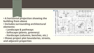
• Defines project boundaries and relation to neighbors & streets
• Identifies the starting point of construction
• Shows surrounding services to support the project
• Indicates the north direction of the land
5.
Title and ContentLayout with List
What is the purpose of a layout design checklist?
The purpose of a layout design checklist is to ensure that all elements of a design
have been properly implemented and meet the desired goals. A checklist helps
designers stay organized and on track, and ensures that no important details are
overlooked.
6.
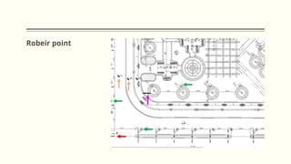
The Robeir(Starting or Zero Point)
Usage: It is a point called the zero point, with coordinates (0.0).
It is a fixed point that does not change, from which the project coordinates can be
set out for execution.
Commonly, the street manhole is used as the robeir because it is considered a
stable point.
Drawing:
Represented by using the elevation circle symbol with the coordinate (0.0).
It is recommended to draw it in a relatively large size so that it is clear on the plan, as it is the
most important reference point for starting project execution.
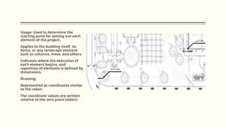
Usage: Used todetermine the
starting point for setting out each
element of the project.
Applies to the building itself, its
fence, or any landscape element
such as columns, trees, and others.
Indicates where the execution of
each element begins, and
repetition of elements is defined by
dimensions.
Drawing:
Represented as coordinates similar
to the robeir.
The coordinate values are written
relative to the zero point (robeir)
10.
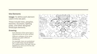
Site Elements
Usage: Todefine each element
used in the site plan.
These include trees, pergolas,
benches, fountains, lighting
poles, and other designed
landscape elements.
Drawing:
Each element of the same type is
represented by the same symbol.
Different subtypes of the same
element are given different
numbering.
For example, trees are symbolized
by (T). Palm trees may be labeled
(T1), while another tree type may be
labeled (T2), and so on for the rest
of the elements.
12.
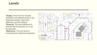
Levels
•Usage: Since thesite includes
sidewalks and different levels in the
landscape design, each level
difference must be defined.
•Drawing: The level difference is
marked with its elevation so it can
be executed.
•Reference: The zero level is
considered the street level (asphalt).
13.
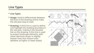
Line Types
LineTypes
Usage: Used to differentiate between
the lines in the drawing and to make
the site plan easy to read.
Drawing: A thick line is used to define
and highlight the building boundary in
the site plan, making it the heaviest
line on the drawing. A thin line is used
to project landscape elements, with
closer elements drawn in slightly
heavier lines than distant ones
(whether at higher or lower levels)
14.
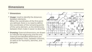
Dimensions
Dimensions
Usage:Used to identify the distances
between elements.
When the coordinates of the first point
are defined, there is no need to define
the coordinates of the remaining points
of the same element, as the dimensions
between them make it easier to describe.
Drawing: External dimensions are drawn
to indicate the beginning and the end.
Internal and detailed dimensions are
added between trees, between columns,
as well as for fountains, benches, and
pergolas
15.
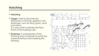
Hatching
Hatching
Usage:Used to illustrate the
differences in finishes applied in the
landscape, such as tiling, grass, sand,
and others.
It is also used to indicate the floor
finish of the building roof.
Drawing: A small portion of the
finishing area is hatched to clarify the
material without overcrowding the
drawing.
Editor's Notes
#1 NOTE:
To change the image on this slide, select the picture and delete it. Then click the Pictures icon in the placeholder to insert your own image.