This document outlines the steps of a science experiment to determine where to place the fulcrum on a lever to require the least amount of force to lift a 50g load. The experiment found that placing the fulcrum closest to the load at 8cm required only 0.1N/10g of force, while placing it farther away at 15cm and 21cm required more force. This supports the hypothesis that the fulcrum placed nearest the load would require the least force. The student was surprised at how little force was needed and learned levers make work easier by reducing the amount of energy or force required.
This presentations explains about the simple pendulum which uses the concept of simple harmonic motion for its oscillations. First part of the video explains about the simple pendulum, the middle part explains about its motion and the final part provides details about a simple experiment that can be done using it.
A method for determining a physical law using the simple pendu.docxransayo
A method for determining a physical law using the simple pendulum as a model
By
name
Lab Partner: name
7 September 2000
Abstract
A process for determining a physical law was executed using the simple pendulum as a
model. The three variables thought most likely to be major influences on pendulum
period were selected. Each variable was tested while holding the others constant.
Displacement affected period, but for displacements less than 10 degrees string length
had the most significant effect on period. The law relating period to string length was
determined. The experimental law did not agree with the accepted law within
experimental uncertainty.
! 1
INTRODUCTION AND THEORY
The simple pendulum system was selected to test a method for determining physical
laws. The method was applied to determine which variables influence the period of the
pendulum. The goal was to derive the law that relates the period of the pendulum to the
most significant variables. A diagram of the simple pendulum is shown in Figure 1.
{Note that I have called out the figure in the text before the figure appears.}
!
Figure 1. Diagram of the simple
pendulum. θ is the displacement angle, L is the
length of the pendulum, g is the acceleration due to
gravity, m is the mass of the pendulum bob, and T is
the tension in the string. {Note: This is Figure 1,
not Figure 1.1. Number your figures and tables
sequentially as they appear in the text. This is a
! 2
stand-alone report, not a report in a sequence of
reports in lab.}
Operational definition of period: Time for pendulum to go from any point
in its motion back to that same point, and traveling in the same direction.
Table 1. is a list of equipment used in the experiment. {Table mentioned
in text before it appears.} {I have taken care to see that the table is all
on one page and does not flow to a second page.}
Table 1. Equipment Used.
Experimental support rod clamped to lab bench
Experimental support arm fastened to support rod
String
Clamped on the experimental support arm
~ 1.1 m long
There was a loop at one end
Pendulum bobs
Six different materials: cork, wood, steel, lead, aluminum, and brass
All bobs had hooks to which the loop in the string was attached
All bobs were the same size as observed by eye
Meter stick
Protractor
PASCO Photogate operating in pendulum mode
PASCO Model 500 Interface
! 3
Pentium computer running Windows NT
Science Workshop Software
Microsoft Excel
{table 1 is where you describe the equipment was used. This is not the place to tell how
it was used. That goes in the experimental procedure in the text.}
DESCRIPTION OF THE EXPERIMENT DATA AND ANALYSIS
Note to students. The nature of this experiment does not lend itself to following
the FORMAT I specified in my e-mail guidance and on my web site. For the formal
reports, use the guidance on the web.
This PPT is created by Areebah and Nimat. We have created this PPT for our Taking Action of Unit-4. We wanted to inform you about how simple machines make our life easier and how they are used in our everyday lives.
UiPath Test Automation using UiPath Test Suite series, part 3DianaGray10
Welcome to UiPath Test Automation using UiPath Test Suite series part 3. In this session, we will cover desktop automation along with UI automation.
Topics covered:
UI automation Introduction,
UI automation Sample
Desktop automation flow
Pradeep Chinnala, Senior Consultant Automation Developer @WonderBotz and UiPath MVP
Deepak Rai, Automation Practice Lead, Boundaryless Group and UiPath MVP
Software Delivery At the Speed of AI: Inflectra Invests In AI-Powered QualityInflectra
In this insightful webinar, Inflectra explores how artificial intelligence (AI) is transforming software development and testing. Discover how AI-powered tools are revolutionizing every stage of the software development lifecycle (SDLC), from design and prototyping to testing, deployment, and monitoring.
Learn about:
• The Future of Testing: How AI is shifting testing towards verification, analysis, and higher-level skills, while reducing repetitive tasks.
• Test Automation: How AI-powered test case generation, optimization, and self-healing tests are making testing more efficient and effective.
• Visual Testing: Explore the emerging capabilities of AI in visual testing and how it's set to revolutionize UI verification.
• Inflectra's AI Solutions: See demonstrations of Inflectra's cutting-edge AI tools like the ChatGPT plugin and Azure Open AI platform, designed to streamline your testing process.
Whether you're a developer, tester, or QA professional, this webinar will give you valuable insights into how AI is shaping the future of software delivery.
Dev Dives: Train smarter, not harder – active learning and UiPath LLMs for do...UiPathCommunity
💥 Speed, accuracy, and scaling – discover the superpowers of GenAI in action with UiPath Document Understanding and Communications Mining™:
See how to accelerate model training and optimize model performance with active learning
Learn about the latest enhancements to out-of-the-box document processing – with little to no training required
Get an exclusive demo of the new family of UiPath LLMs – GenAI models specialized for processing different types of documents and messages
This is a hands-on session specifically designed for automation developers and AI enthusiasts seeking to enhance their knowledge in leveraging the latest intelligent document processing capabilities offered by UiPath.
Speakers:
👨🏫 Andras Palfi, Senior Product Manager, UiPath
👩🏫 Lenka Dulovicova, Product Program Manager, UiPath
Essentials of Automations: Optimizing FME Workflows with ParametersSafe Software
Are you looking to streamline your workflows and boost your projects’ efficiency? Do you find yourself searching for ways to add flexibility and control over your FME workflows? If so, you’re in the right place.
Join us for an insightful dive into the world of FME parameters, a critical element in optimizing workflow efficiency. This webinar marks the beginning of our three-part “Essentials of Automation” series. This first webinar is designed to equip you with the knowledge and skills to utilize parameters effectively: enhancing the flexibility, maintainability, and user control of your FME projects.
Here’s what you’ll gain:
- Essentials of FME Parameters: Understand the pivotal role of parameters, including Reader/Writer, Transformer, User, and FME Flow categories. Discover how they are the key to unlocking automation and optimization within your workflows.
- Practical Applications in FME Form: Delve into key user parameter types including choice, connections, and file URLs. Allow users to control how a workflow runs, making your workflows more reusable. Learn to import values and deliver the best user experience for your workflows while enhancing accuracy.
- Optimization Strategies in FME Flow: Explore the creation and strategic deployment of parameters in FME Flow, including the use of deployment and geometry parameters, to maximize workflow efficiency.
- Pro Tips for Success: Gain insights on parameterizing connections and leveraging new features like Conditional Visibility for clarity and simplicity.
We’ll wrap up with a glimpse into future webinars, followed by a Q&A session to address your specific questions surrounding this topic.
Don’t miss this opportunity to elevate your FME expertise and drive your projects to new heights of efficiency.
Let's dive deeper into the world of ODC! Ricardo Alves (OutSystems) will join us to tell all about the new Data Fabric. After that, Sezen de Bruijn (OutSystems) will get into the details on how to best design a sturdy architecture within ODC.
Key Trends Shaping the Future of Infrastructure.pdfCheryl Hung
Keynote at DIGIT West Expo, Glasgow on 29 May 2024.
Cheryl Hung, ochery.com
Sr Director, Infrastructure Ecosystem, Arm.
The key trends across hardware, cloud and open-source; exploring how these areas are likely to mature and develop over the short and long-term, and then considering how organisations can position themselves to adapt and thrive.
"Impact of front-end architecture on development cost", Viktor TurskyiFwdays
I have heard many times that architecture is not important for the front-end. Also, many times I have seen how developers implement features on the front-end just following the standard rules for a framework and think that this is enough to successfully launch the project, and then the project fails. How to prevent this and what approach to choose? I have launched dozens of complex projects and during the talk we will analyze which approaches have worked for me and which have not.
Connector Corner: Automate dynamic content and events by pushing a buttonDianaGray10
Here is something new! In our next Connector Corner webinar, we will demonstrate how you can use a single workflow to:
Create a campaign using Mailchimp with merge tags/fields
Send an interactive Slack channel message (using buttons)
Have the message received by managers and peers along with a test email for review
But there’s more:
In a second workflow supporting the same use case, you’ll see:
Your campaign sent to target colleagues for approval
If the “Approve” button is clicked, a Jira/Zendesk ticket is created for the marketing design team
But—if the “Reject” button is pushed, colleagues will be alerted via Slack message
Join us to learn more about this new, human-in-the-loop capability, brought to you by Integration Service connectors.
And...
Speakers:
Akshay Agnihotri, Product Manager
Charlie Greenberg, Host
Slack (or Teams) Automation for Bonterra Impact Management (fka Social Soluti...Jeffrey Haguewood
Sidekick Solutions uses Bonterra Impact Management (fka Social Solutions Apricot) and automation solutions to integrate data for business workflows.
We believe integration and automation are essential to user experience and the promise of efficient work through technology. Automation is the critical ingredient to realizing that full vision. We develop integration products and services for Bonterra Case Management software to support the deployment of automations for a variety of use cases.
This video focuses on the notifications, alerts, and approval requests using Slack for Bonterra Impact Management. The solutions covered in this webinar can also be deployed for Microsoft Teams.
Interested in deploying notification automations for Bonterra Impact Management? Contact us at sales@sidekicksolutionsllc.com to discuss next steps.
Transcript: Selling digital books in 2024: Insights from industry leaders - T...BookNet Canada
The publishing industry has been selling digital audiobooks and ebooks for over a decade and has found its groove. What’s changed? What has stayed the same? Where do we go from here? Join a group of leading sales peers from across the industry for a conversation about the lessons learned since the popularization of digital books, best practices, digital book supply chain management, and more.
Link to video recording: https://bnctechforum.ca/sessions/selling-digital-books-in-2024-insights-from-industry-leaders/
Presented by BookNet Canada on May 28, 2024, with support from the Department of Canadian Heritage.
Transcript: Selling digital books in 2024: Insights from industry leaders - T...
Levers
1. Step 1: Pick a Topic
Force and Motion: Levers
Step 2: Research
• http://www.sciencebuddies.org/sciencefair
projects/project_ideas/Phys_p014.shtml?
fave=no&isb=c2lkOjEsaWE6UGh5cyxwOjEscmlkOjUxMzA0MjI&from=TSW
• http://www.enchantedlearning.com/physics/machines/Levers.shtml
• http://www.fearofphysics.com/Seesaw/seesaw.html
• http://www.sciencebuddies.org/sciencefair
projects/project_ideas/Phys_p065.shtml?
fave=no&isb=c2lkOjEsaWE6UGh5cyxwOjEscmlkOjUxMzA0MjI&from=TSW
• http://www.pbs.org/parents/cyberchase/show/episodes/604.html
• http://en.wikipedia.org/w/index.php?title=Lever&oldid=198005759
• Stop Faking It! Energy, by William C. Robertson
Step 3: Question
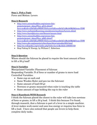
Where should the fulcrum be placed to require the least amount of force
to lift a 50 g load?
Step 3: Variables
Manipulated Variable: Placement of fulcrum
Responding Variable: N of force or number of grams to move load
Controlled Variables:
• Same cup on each end
• Same Wooden Ruler and pen (as the fulcrum)
• Same amount of load (50 g)
• Newtons or grams measured when ruler is touching the table
• Same amount of tape holding the cup to the ruler
Step 4: Hypothesis WITH Research
I think the fulcrum placed the closest to the ruler will take less newtons
of force or grams, to lift a 50 g load. I think this because I’ve found,
through research, that a fulcrum is part of a lever in a simple machine.
A lever makes work easier and uses less energy or requires less force to
lift a load. I have also noticed that people use levers to help them
complete daily tasks.
2. Step 5: Materials List
Wooden Ruler 12 inches (30 cm)
1 or 2 Plastic Bathroom Cups 3oz (88.7 mL)
Ink Pen with cap
50 g weight
Push Pull Spring Scale or Metal Washers for gram weights
Masking Tape
Step 6: What’s the Plan?
1. Research
2. Details of testing – see variables
3. Measurable results newtons and/or grams
4. Log
5. Repeat test – 3 trials
Step 7: Procedure
1. Build Lever
a. Use 5 cm of masking tape rolled under each cup.
b. If using metal washer to measure grams, place each cup at
the end of the ruler.
c. If using the push pull spring scale to measure, only use one
cup.
d. Put a 50g piece in one cup at the 0 cm end, this is the load.
2. Place the fulcrum, pen, at the 21 cm mark on the lever. Hold pen
in place with one hand.
3. Measuring Force:
a. Use the push end of the push pull spring scale to push down
on the rulers end until the ruler touches the table.
b. Place gram pieces into the cup until the ruler touches the
table.
4. Record results, and repeat two more times for three trials.
5. Repeat procedure with fulcrum, pen, at 15 cm and 8 cm marks on
the ruler.
3. Step 8: Data
Fulcrum Trial 1 Trial 2 Trial 3
21 cm 1.5N / 150g 1.5N / 150g 1.5N / 150g
15 cm .5N / 50g .5N / 50g .5N / 50g
8 cm .1N /10g .1N / 10g .1N / 10g
Step 9: Discussion of Results/Charts & Graphs/Pictures
Setting the fulcrum at 8 cm, which was closest to the load, took the
least amount of effort or grams to lift the load. The lever produced a
force of .1N/10g to lift the load of 50 g. When the fulcrum was set at 15
cm, it took .5N/50g of force to lift the 50 g load. The measurement
furthest from the load produced the most amount of effort with
1.5N/150g of force to lift a 50 g load.
8. Step 10: Conclusion
My hypothesis was that the fulcrum placed closest to the load on the beam
will take the least amount of newtons or grams, to lift the load. The
results indicate my hypothesis should be accepted. The fulcrum placed closest to
the load, 8 cm, took the least amount of effort to move a 50 g load.
This experiment proved that the easiest way to move a load with a lever is to place
the fulcrum close to the load. When the fulcrum was places at 8 cm, it only took a
force of .1N/10g. As the fulcrum moves further from the load, more force is
required to lift the load. At 15 cm it took .5N/50g to lift the load, and at 21 cm it
took even more effort by using the 1.l5N/150g of force.
Even though I was correct in my hypothesis, I was surprised how little force it took
to lift a load of 50 g. I learned that when the fulcrum is placed in the middle, the
work done on the system is equal to the work done by the system. That is why it
took .5N/50g of force to move a 50g load. Through further research I also learned
that each time you change the position of the fulcrum you change the load’s
gravitational potential energy by raising the load up. This means that the effort
arm distance is also changing. So, when moving the fulcrum closer and farther
away from the middle there is a difference in the distance you have to push down
on the effort arm end, which means the load arm requires different amounts of
effort. When the fulcrum is close to the load, the effort arm has a greater distance
to move and the load arm has less of a distance to move. Where the fulcrum is
farther away from the load, the effort arm has a smaller distance and the load arm
has to move the load a further distance. See chart below.
Fulcrum Load Arm Effort Arm
8 cm 1 cm 3.3 cm
15 cm 1.9 cm 1.9 cm
21 cm 2.6 cm 1.2 cm
I have learned that people use fulcrums everywhere is their daily lives to make
work easier. Just in preparing my science project I used scissors and a stapler
which are both levers. Both simple machines make work easier by using less
energy to do work.
Because of the results of this experiment, I wonder if changing the thickness of the
fulcrum would have made a difference in the results. This would be a very
interesting variable to change and see if there is a difference in the results.