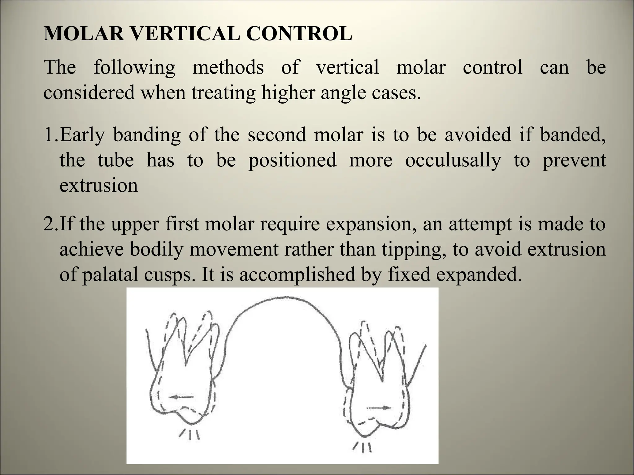
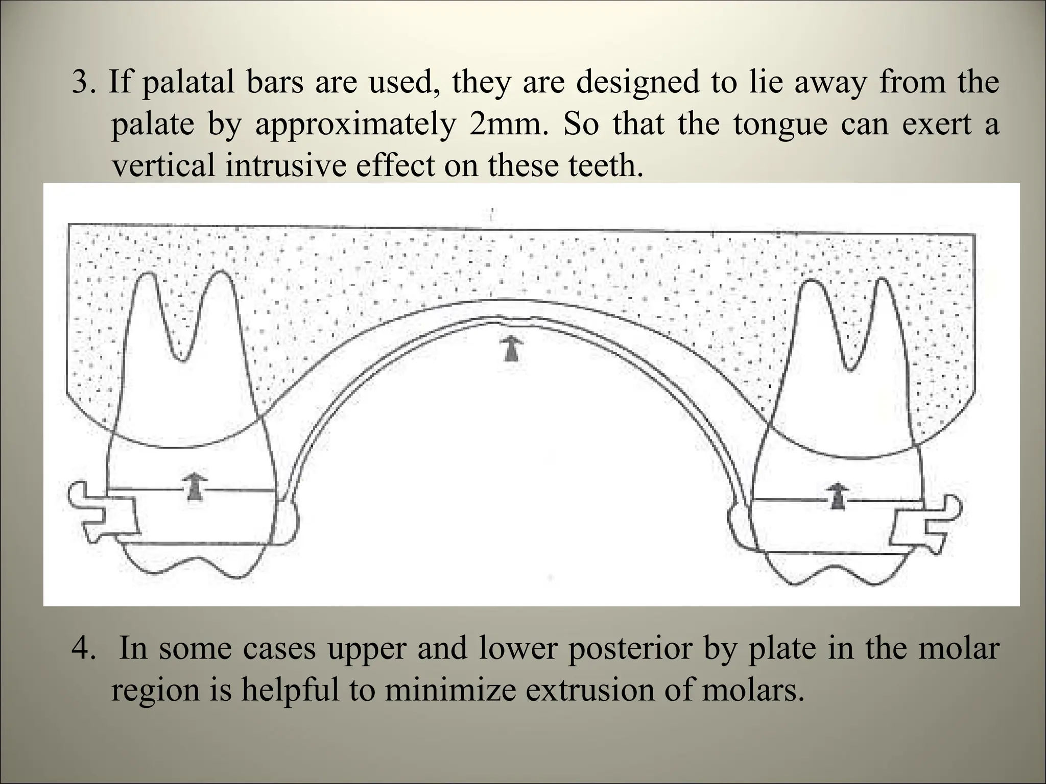
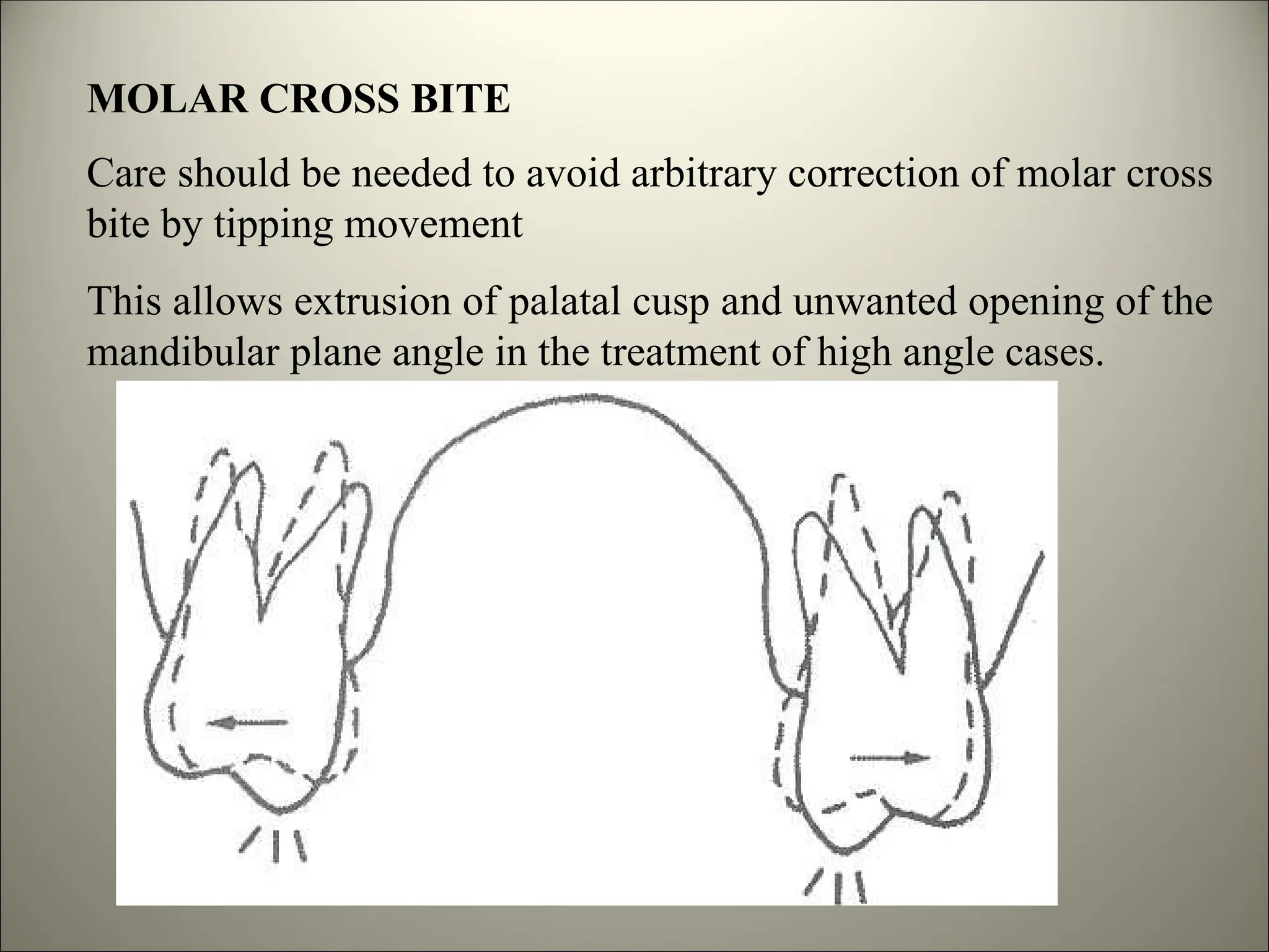
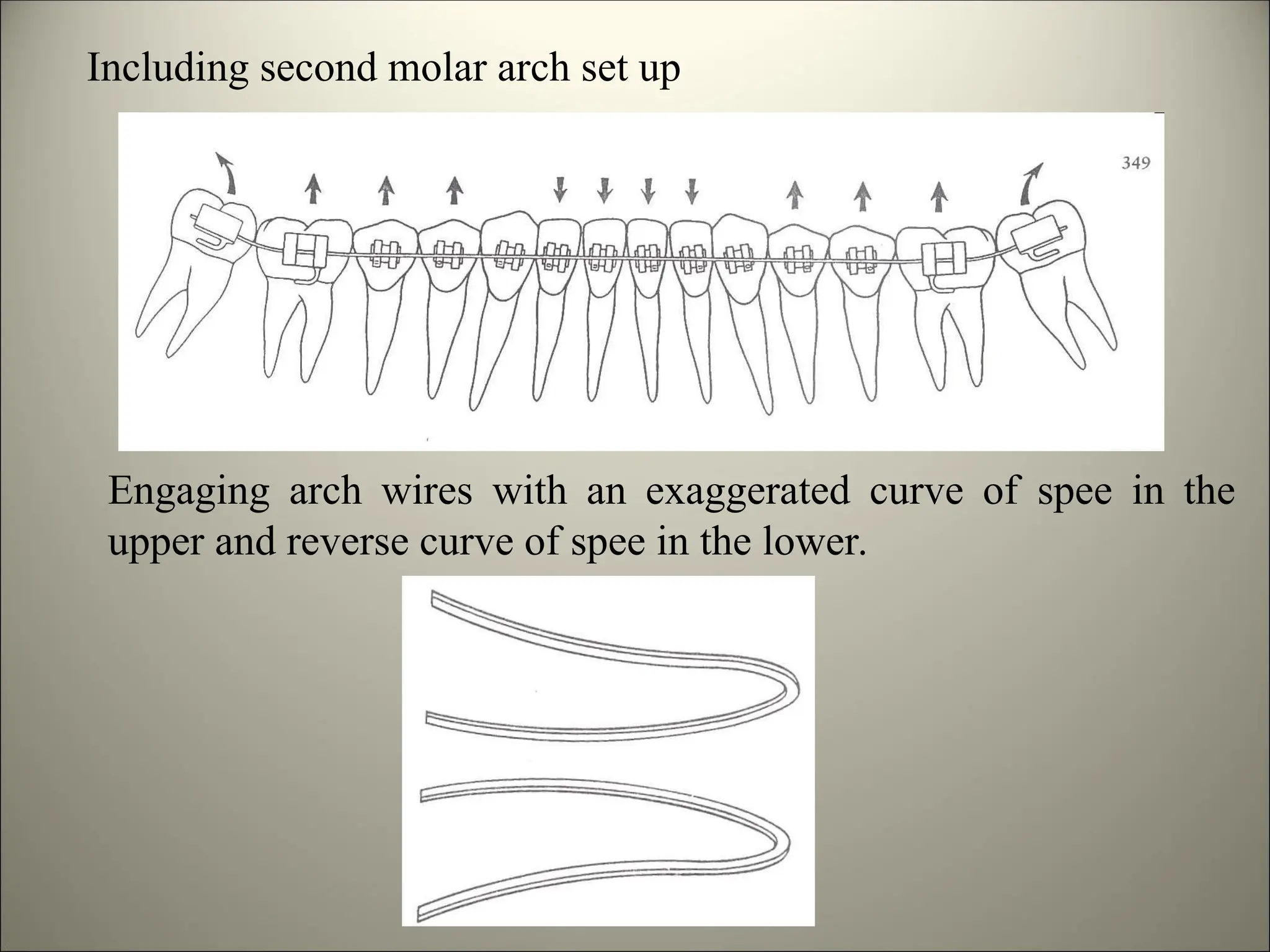
LEVELING AND ALIGNING IN PREADJUSTED APPLIANCE
INTRODUCTION
 Leveling and aligning is the fundamental objectives of
orthodontics during the initial phase of treatment.
 In most technique this stage is required before correction of major
aspect of the malocculusion, such as overjet reduction (or) space
closure and PEA is no exception to this.
 The great majority also have either excessive overbite, resulting
from some combination of excessive curve of spee in the lower arch
and absent in upper arch.
 A minority of cases have an anterior open bite caused by
excessive curve of spee in upper arch offset in lower arch.
 Therefore the purpose of this initial phase of treatment in PEA is
to bring the teeth into alignment and correct the vertical discrepancy
by leveling out of the arch.
WIRES USED IN LEVELING AND ALIGNING
Stainless steel wires
Australian stainless steel wires
Cobalt-chromium (Elgioy)
Beta-titanium (TMA)
A-niti
M-niti
Coaxial wires
Braided wires
Composite plastics/optical glass
STAINLESS STEEL WIRES
Stainless steel wires used in orthodontics, consist of 18%
chromium and 8% Nickel with austenitic type of steel.
It has tarnish and corrosion resistance due to passivating
effect of chromium.
The property of stainless steel wires can be controlled
reasonably wide range by varying the amount of cold working
and annealing during manufacture.
This steel is softened by annealing and hardened by cold
working.
Fully annealed stainless steel wires of soft and highly
formable.
AUSTRALIAN STAINLESS STEEL WIRES
The Australian stainless steel wires was produced
A.J.Willcock according to specifications.
Specified by Dr. Begg, Without which as Dr. Begg, himself
says “The Begg Technique would not have developed”.
It has ultra high tensile austenitic stainless steel wire.
It comes in different resiliencies.
This wires are graded and colour coded depending on the
resiliency.
1. Regular with white label.
2. Regular plus with green label
3. Special grade with black label
4. Special plus with orange label
5. Premium with blue label
6. Premium plus with blue label
7. Supreme with lavender label
The regular grade is least and premium grade is the most
resilient of all the wires.
For leveling and aligning special plus and above the wires are
used.
COBALT CHROMIUM ALLOY WIRES
This alloy is colour coded according to their resiliency
1. Blue elgiloy
2. Yellow elgiloy
3. Green elgiloy
4. Red elgiloy
Blue being the least resilient and red being more resilient.
A distinct advantage with these wires is that they can be heat
treated, so increase the resiliency.
Therefore, the clinicians can place accurate bend with easy in
preheat treatment wires.
After preheat treatment the same wire obtained better spring
back properties
NICKEL TITANIUM ALLOY WIRES (NiTiNol)
 Invented in 1960 by William f. Buehler
 At novel ordanance laboratory (Nol) in silver springs. Now
called navel surface weapon centre.
 Acronym of elements - Ni – Nickel
Ti – Titanium
Nol - Origin
INTRODUCTION TO ORTHODONTICS
Introduced by George Anderson in 1971.
Clinical use started 1972.
Marketed by unitek.
NiTiNol have to remarkable properties
1. Shape memory
2. Super elasticity
M-niti
After considerable experimentation, nitinol was marketed in the
late 1970s for orthodontic use in stabilized martensitic form.
It is exceptionally springiness and quite strong but has poor
formability.
The family of stabilized martensitic alloys now commercially
available are reffered as M-niti.
In late 1980s, new nickel titanium wires with an active austenitic
grain structure appeared.
These wires exhibit the other remarkable property of NiTi alloy-
super elasticity.
It is reffered as A-niti
The wire has spring back 4-4 times that of comparable stainless
steel wire and 1.6 times of NiTiNol.
At 80% activation average stiffness of NiTi is 73% that of
stainless steel and 36% that of NiTiNol.
The load deformation rate at small activation is considerably
higher that of large activation.
Highly suitable wire if large deflection and low stiffness required.
A-niti
BETA TITANIUM (TMA)
In the early 1980s, after Nitinol but before A-niti, a quite
different Titanium alloy, Beta titanium was introduced into
orthodontics.
It offers highly desirable combination of strength and
springiness as well as reasonably good formability.
This is excellent choice of auxiliary springs and intermediate
and finishing arch wires.
Its property is intermediate between stainless steel and M-niti.
MULTI STANDARD/ CO-AXIAL STAINLESS STEEL WIRES
The wires available in
1. Round
2. Rectangular
3. Square in cross section
According to studies conducted by Kusy & Barrow in 1982.
Brided wires have elastic properties similar to nitinol.
It can be used as a suitable to nitinol considering the cost of the
later.
COMPOSITE PLASTICS
Optiflex is a composite structure formed by top coating optical
glass fibres (which are pure silicon dioxide) with a hot melt
adhesive and a nylon skin.
Its advantages are light forces for initial alignment and excellent
esthetics.
LEVELING AND ALIGNING
Definition
The tooth movements needed to achieve passive engagement of a
plain, rectangular arch wire of .019/.025 dimension, having
standard arch form into correctly placed preadjusted .022” bracket
system.
In case of 0.018” bracket system the dimension of arch wire
should be 0.016/0.022.
THE OBJECTIVE OF LEVELING AND ALIGNING
The objective in leveling and aligning can be divided into
1. Short term objectives
2. Long term objectives
Short Term Objectives
In the opening months of treatment, will be to achieve proper
leveling and aligning into passive rectangular wire.
Long Term Objectives
To be achieved by the end of the treatment, will be to achieve an
ideal dentition, showing in the six keys to normal occlusion, and
with the dentition properly positioned in the facial profile.
Any attempt to rush the achievement of short term objectives by
taking short cuts and using heavy forces, cause unwanted changes
to the take place. These make achievement of long term
objectives more time consuming and difficult.
So we have choose carefully about the leveling and aligning
wires.
If we choose properly, it will safely and smoothly take as to both
our short term and long term goals.
THE PRINCIPLES IN THE CHOICE OF LEVELING AND
ALIGNING WIRES
1. The initial arch wires for alignment should provide light
continuous force to produce the most efficient tipping tooth
movement.
2. The arch wire should move freely, with minimal binding,
within the bracket slot.
3. Sliding teeth along an arch wire requires atleast 0.002” of
clearance and 0.004” would be ideal.
4. During initial alignment, it is better to position the crowns
than to cause root displacement. Although a highly resilient
wire such as 0.017” x 0.025” A-niti could be used during this
stage it is not advisable because it will create unnecessary and
desirable root movements which delay the alignment process
and possibility of root resorption.
ARCH WIRE MATERIALS
The wires used for initial alignment purpose require a
combination of excellent strength, springiness and long range of
action.
Ideally there should be an a almost flat-load deflection curve with
the wire delivering about 50gm of force of almost any degree of
deflection.
The titanium based arch wire both NiTi and TMA offer a better
combination of strength and springiness than stainless steel wires.
The NiTi wires are particularly useful in first stage of treatment,
remarkably flat load deflection curve of A-niti make it the wire of
choice for leveling and aligning.
SIZE OF THE WIRES
Changing the diameter of a wire greatly affects its properties for
initial leveling and aligning the smallest diameter wire that
has adequate strength would be proffered.
When the diameter of wire is doubled,
1. The strength increases by 8 times.
2. The springiness decreases by 16 times.
3. Range decrease by half.
DISTANCE BETWEEN THE BRACKETS
As the distance increases between the point of attachment of a
beam, strength decreases rapidly while springiness increases even
more rapidly.
The bit of the bracket is an important factor.
The wider the individual bracket, the smaller the interbracket
span.
So gaining increased springiness and the range of action, withiout
sacrifying too much strength.
LEVELING AND ALIGNING ARCH WIRE SEQUENCE
ARCH WIRE SEQUENCE FOR .018” SLOT BRACKETS
Selection of initial alignment wires
The principle that there should be .002” of clearance for initial
wires means that .016” round wire is the largest that should be
considered for initial alignment in the .018” slot.
The three major possibilities for alignment arches are
1. Multi standard stainless steel wires
2. Nickel titanium wires
3. Single standard steel wires
MULTISTANDARD WIRES
Its excellent properties, .0175” multistandard stainless steel wire
is too large for effective use .018” slot bracket.
The difficulty of sliding the teeth along with .0175” wires in .018”
slot brackets is compounded irregular surface of the twisted
strands, which can be bind against the corner of brackets.
A .015” wire gives adequate clearance but its physical properties
are inferior, so this wire is can be eliminated as impractical.
NICKEL TITANIUM WIRES
In contrast to steel wires that tend to be too stiff and not strong
enough for good alignment.
niti wires have outstanding properties of springiness and range
and also good strength.
M-niti does provide good formability. In clinical practice, it has
tendency to break and permanently distorted if stressed to the
same extent.
A-niti wires of the same diameter of .016” can have different
force deflection curve, with these wires, the appropriate choice for
initial alignment is the wire delivers 50 gms along its unloading
curve.
The great advantage is that the wire will deliver this optimum
force over a large range.
STAINLESS STEEL WIRES WITH LOOPS
Excellent performance in alignment also can be obtain by
using .014” or .016” stainless steel wires incorporating loops if
necessary.
The primary indication choosing loop in a .014” steel wires, when
the arch is well aligned except at one spot, where the tooth badly
mal positioned tooth, there is risk for distorting arch form.
In such situation arch wire should be reasonably stiff except at the
spot where springiness needed and loops will produced just that
effect.
.014” stainless steel wire used to align the teeth further. After a
lapse of 1-6 weeks .016” round stainless steel wire is ligated.
Finally .016” x .022” stainless steel wire is ligated to complete the
phase of leveling and aligning.
ARCH WIRE SEQUENCE FOR .022” SLOT
MULTISTANDARD WIRES
With a .022” slot, there is optimum clearance for .0175” twisted
arch wires and this wires can be excellent choice of initial
alignment arch wire, if mal aligned is not severe.
Although .0195” twisted wire also would fit well within the
bracket slot but this wire is undesirably stiffer.
.0195 co-axial wire has similar springiness that of .0175” twisted
wire, and is better choice if some reason a large diameter wire is
desired.
Because coaxial wires cost more than twisted wires.
NICKEL TITANIUM WIRES
Both .016” and .018” diameter NiTi can be used initial arch wires
with .022” slot brackets.
.018” M-niti undesirably stiffer and should be avoided.
A-niti is readily available in .016” diameter. Although there will
be .008” clearance within the brackets with such wires does not
cause clinical problems.
Since the stiffness of .0175” twisted wires and .016” NiTi wires is
quite similar at small deflections.
It make good economic sense to use the twisted wires
initially .022” slot.
When the teeth reasonably well aligned initially and use .016”
NiTi when greater range needed.
STAINLESS STEEL WIRE WITH LOOPS
.014” stainless steel wires usually the best choice.
But .016” stainless steel wires can also be used.
But the wire fits better in .022” slot, but its greater stiffness
requires more complex loop design.
Once the initial alignment is achieved, the diameter of wire
progressively increased to .016”, .018”, .020” round wires.
And finally .0195” x .025” rectangular stainless steel wire is
placed to complete the leveling and aligning.
BENNET and MC LAUGHLIN advice the following sequence of
arch wire in .022” slot.
1. .015” twist flex
2. .0175” twist flex
3. .014” stainless steel round wires
4. .016” stainless steel round wires
5. .018” stainless steel round wires
6. .020” stainless steel round wires
7. .019” x .025” rectangular stainless steel wire
The exact sequence of arch wire varies with the complexity of
mal occlusion.
In difficult cases a particular size may be maintained for more
than one month.
In initial cases, it is often possible to skip a wire size.
BENNET and MC LAUGHLIN did not discourage the use of
NiTi wires, he says the NiTi wires disadvantages
The cost, the flexibility, difficulty to place bend back
Anchorage control in the PEA system is very important, because
of the features built in the appliances, which tend to proclaine
the teeth.
During the leveling and aligning will have the following meaning
The maoeuvers used to restrict undesirable changes during the
opening phase of treatment, so that leveling and aligning is
achieved without key features of the malocclusion becoming
worse.
BENNET and MC LAUGHLIN emphases the need to consider
anchorage in all the three plane of space
1. Horizontal plane
2. Vertical plane
3. Transverse plane (Lateral)
ANCHORAGE CONTROL DURING LEVELING AND
ALIGNING IN PEA
Horizontal plane
Anchorage control means limiting the mesial movement of the
posterior segments while encouraging distal movement of the
anterior segments.
When the posterior mesialize and the anterior procline, anchorage
is being lost in the horizontal plane.
Vertical plane
Vertical anchorage control involve the limitation of the vertical
skeletal and dental development in the posterior segments and the
limitation of the vertical eruption of (or) even intrusion of the
anterior segments.
Transverse (Lateral) anchorage control
It comprises maintenance of expansion procedure, primarily in the
upper arch, and the avoidance of tipping (or) extrusion of
posterior teeth during expansion.
Control of anchorage in the horizontal plane
Anchorage control in the horizontal plane includes the
achievement of the correct antero posterior position of the
teeth at the end of the treatment.
It often involves limiting the mesial movement of the posterior
teeth while encouraging the distal movement of the anterior
teeth.
This can be divided into
1. Anchorage control of anterior segments
2. Anchorage control of posterior segment
Anterior control of anterior segments
The first difference between the standard edge wise appliance and
the PEA is the tendency for the anterior teeth to incline forwards
during the initial phase of leveling and aligning.
This result from the tip built in the anterior brackets which is
more in the upper arch compared to the lower arch.
To eliminate or minimize this effect by connecting anterior
segments to the posterior segments with elastic forces.
In the elastic force were greater than the leveling force of the arch
wire, there was tendency for anterior teeth to tip and rotate
distally, and increasing the curve of spee, deepening the bite.
This phenomenon is known as “ROLLER COASTER”.
This was particularly evident in first premolar extraction cases.
This “ROLLER COASTER” effect is minimized by Andrews and
later by ROTH.
They introduce features into the bracket system to prevent
unwanted changes.
1. Extra torque was built into incisor bracket
2. Anti tip, antirotation features built into canine, premolar and
molar brackets.
3. Power arms were added to some brackets to bring the forces
closer to the centre of resistance of each tooth.
BENNET and MC LAUGHLIN took a different root,
They introduce lace backs to reduce or minimize this side effects.
The lace backs are constructed by 0.009” (or) 0.0010” ligature
wires and tied in figure of eight fashion. They extend from the
most distally banded molars to the canine in all quardrants and
have proven effective in controlling the canine during leveling
and aligning.
The lace back prevent the cuspids from the tipping forward and
can also be used for distalizing (or ) retracting the canines.
WALKING CANINES
BEND BACKS
Bending the arch wire immediately behind the most distally
banded posterior tooth is called chinching.
It serves to minimize forward tipping of incisors.
IN SUMMERY
The primary methods of anterior anchorage control during
leveling and aligning include:
Using lace backs to minimize the forward tipping of the canines
and effectively retract them when indicated.
1. Using bend backs to minimize forward tipping of incisors.
ANCHORAGE CONTROL IN THE UPPER POSTERIOR
SEGMENT
In certain cases it may be necessary to limit or prevent the
posterior segment from moving forward, maintain their position,
(or) even distalize them.
Posterior anchorage requirements normally greater upper arch
than in lower arch.
Because of the following reason.
1.The upper anterior segments has longer than lower.
2.The upper anterior brackets have greater amount of built in tip.
3.The upper incisors require more torque control and bodily
movement than lower arch.
4.The upper molar usually move mesially more readily than the
lower arch
Because of these factors, extra oral force normally the most
effective way to provide posterior anchorage control in the upper
arch.
BENNET and MC LAUGHLIN favour a combination of head
gear (occipital and cervical pull).
The force levels used for combination of head gears are 150 –
250gms.
Keeping the force directed slightly above the occulusal plane and
minimize the tendency for vertical extrusion of the upper
posterior teeth, while simultaneously allowing effective
distalization of molar.
The length of the outer bow of the head gear is important to avoid
unwanted molar tipping.
A secondary method of anchorage support in the upper posterior
segments is palatal bar.
This is normally placed when the upper molars has been properly
rotated and or situated c-1 molar relation.
The palatal bar can be constructed of heavy .045” (or) .051”
round wire, extending from molar to molar with a loop placed in
the middle of the palate and the arch wire above (2mm) from the
roof of the palate and its soldered to the molar hook.
ANCHORAGE CONTROL OF POSTERIOR SEGMENTS IN
LOWER ARCH
When extra anchorage support is needed in the lower posterior
segments, we can use
1. Lingual arch
2. C-111 elastics
3. Lip bumper
ANCHORAGE CONTROL IN VERTICAL PLANE
There are two important areas of anchorage control in the vertical
plane
Incisor control
In PEA produce a transitional deepening of anterior over bike
during leveling and aligning.
Mainly due to tip of the canine brackets. If canines are tipped
distally, the mesial aspect of the canine bracket slot. Directed in
the occlusal direction.
This effects avoided either by not initially bracketing the incisor
(or) by not tying the arch wire into the incisor bracket, until the
canine roots have been uprighted and moved distally under
control of lace back.
It is important to avoid early arch wire engagement of high label
canines.
So that unwanted vertical movements of lateral incisors and
premolar does not occur.
MOLAR VERTICAL CONTROL
The following methods of vertical molar control can be
considered when treating higher angle cases.
1.Early banding of the second molar is to be avoided if banded,
the tube has to be positioned more occulusally to prevent
extrusion
2.If the upper first molar require expansion, an attempt is made to
achieve bodily movement rather than tipping, to avoid extrusion
of palatal cusps. It is accomplished by fixed expanded.
3. If palatal bars are used, they are designed to lie away from the
palate by approximately 2mm. So that the tongue can exert a
vertical intrusive effect on these teeth.
4. In some cases upper and lower posterior by plate in the molar
region is helpful to minimize extrusion of molars.
ANCHORAGE CONTROL IN THE LATERAL PLANE
Anchorage control in the lateral (or) transverse plane involves the
maintenance expansion procedure mainly upper arch, and to
avoidance of tipping and extrusion of the posterior teeth during
the expansion phase.
MAINTAINING INTERCANINE WIDTH
During the treatment, the intercanine width should not be altered
to a great extent.
Expansion of the arches should be controlled to prevent relapse
and care should be taken to ensure that crowding is not relieved
by uncontrolled expansion of the upper and lower arch.
MOLAR CROSS BITE
Care should be needed to avoid arbitrary correction of molar cross
bite by tipping movement
This allows extrusion of palatal cusp and unwanted opening of the
mandibular plane angle in the treatment of high angle cases.
Whenever possible molar cross by should be corrected by bodily
movement.
Minimal molar cross bite can be corrected effectively by
expanding the arch wire.
SPECIAL PROBLEMS DURING LEVELING AND
ALIGNING
1. Deep overbite correction
2. Cross bite correction
3. Rotation
Deep Overbite
Moderate deep bite cases get corrected as a result of routine
leveling and aligning procedure.
Severe deep bite cases require different corrective procedure.
Types of Deep Overbite
1. True deep overbite
2. Pseudo deep overbite
True deep bites is mostly due to infra eruption of the posterior
teeth.
Pseudo deep bite due to supra eruption of anterior teeth.
Corruption of deep overbite is accomplished by various tooth
movements
1. Extrusion of posterior teeth
2. Uprighting of posterior teeth
3. Increasing the inclination of incisors
4. Intrusion of anterior teeth
EXTRUSION AND UPRIGHTING OF POSTERIOR TEETH
This method is indicated in
1. A patient with horizontal growth pattern
2. Growing individuals
3. True deep overbite cases
This method is accomplished by
1. Anterior bite plane- which allows the posterior teeth to supra
erupt thereby opening of the bite
Including second molar arch set up
Engaging arch wires with an exaggerated curve of spee in the
upper and reverse curve of spee in the lower.
INCREASE THE INCLINATION OF ANTERIORS
This procedure should be employed in the patient who has normal
skeletal pattern but dentally retroclined (or) crowded anteriors.
This can be achieved in PEA by not giving either lace back or
bend back.
INTRUSION OF ANTERIOR TEETH
Indicated in
1. Vertical skeletal growth pattern
2. Pseudo overbite
This is accomplished by
1. Utility arches
2. Burstone’s segmental arch mechanics
Utility arches
The utility arch has multiple uses in various orthodontic
treatment.
This auxiliary arch wire was developed according to the
biomechanical principles described by Burstone and refined by
Ricketts for bioprogressive therapy
When a round wire with a reverse curve of spee is engaged in the
lower arch to level the curve or spee, it produces mild distal
tipping uprighting of the molars, extrusion of the premolars and
flaring of the incisors.
In order to restrict this unwanted tooth movements true intrusion
of the incisors is required.
Blue elgiloy of 0.016” x or 0.016” or 0.016” x 0.022” dimension
in an 0.022” slot is material for fabrication of utility arches.
Utility arch can even be made with 0.014” or 0.018” round wires.
SALIENT FEATURES OF UTILITY ARCH
TYPES OF UTILITY ARCHES
1. Passive utility arch
2. Intrusion utility arch
3. Retrusion utility arch
4. Protrusion utility arch
Passive utility arch
It can be used for stabilization (or) as a space maintainer.
It is ideal in the mixed dentition as it permits the eruption of
canine and premolars
Intrusion utility arch
Retrusion utility arch
Protrusion utility arch
TIPBACK SPRINGS (INTRUSION SPRINGS)
Originally proposed by Burstone, these springs are made of
0.017” x 0.025” TMA wire.
The springs are indicated in
1. Growing patient with forward growth rotation.
2. Very deep curve of spee in the lower arch.
3. Pseudo deep bite cases.
THREE PIECE INTRUSION ARCH
This consist of following parts :
1. Posterior anchorage unit
2. The anterior segment with posterior extension
3. Intrusion cantilevers
ROTATION CORRECTION
It is defined as perversion of the tooth around its long axis or any
parallel axis.
Correction of bilateral molar rotations
To correct bilaterally rotated molars (mesial-in, distal out
rotation) two equal and opposite moments are applied to the
molars.
An alternate way to obtained equal and opposite moments to
derotate molars is to use a high pull head gear with an occlusal
insertion of the inner bow in the buccal tubes on the molar bands.
The force of high pull head gear is directed through the center of
resistance of maxillary first molar. The distal force applied
through the buccal tube of the molars buccal to the center of
resistance and creates a moment that tends to rotate the molars
mesial out.
CORRECTION OF UNILATERAL MOLAR ROTATION
Unilateral activation is incorporated into the horizontal tab of the
transpalatal arch..
The opposite molar will experience a tip back moment.
If such side effects or not desirable, it is necessary to place 0.017”
x 0.025” ss wire from right maxillary molar to the left second
premolar for anchorage purpose.
CROSS BITE CORRECTION
It is defined as cross bite as an abnormal buccal, labial or lingual
relationship of a tooth or teeth of maxilla, the mandible, or both,
when the arches are in occlusion.
It is corrected by
1. Transpalatal arch
2. Quad-helix
3. Cross elastics
4. Heavy labial expansion arch
5. Expansion screws to move one or two teeth
6. pendulum appliance with screw

levelling and alignment in preadjusted appliance.ppt

  • 1.
    LEVELING AND ALIGNINGIN PREADJUSTED APPLIANCE INTRODUCTION  Leveling and aligning is the fundamental objectives of orthodontics during the initial phase of treatment.  In most technique this stage is required before correction of major aspect of the malocculusion, such as overjet reduction (or) space closure and PEA is no exception to this.  The great majority also have either excessive overbite, resulting from some combination of excessive curve of spee in the lower arch and absent in upper arch.  A minority of cases have an anterior open bite caused by excessive curve of spee in upper arch offset in lower arch.  Therefore the purpose of this initial phase of treatment in PEA is to bring the teeth into alignment and correct the vertical discrepancy by leveling out of the arch.
  • 2.
    WIRES USED INLEVELING AND ALIGNING Stainless steel wires Australian stainless steel wires Cobalt-chromium (Elgioy) Beta-titanium (TMA) A-niti M-niti Coaxial wires Braided wires Composite plastics/optical glass
  • 3.
    STAINLESS STEEL WIRES Stainlesssteel wires used in orthodontics, consist of 18% chromium and 8% Nickel with austenitic type of steel. It has tarnish and corrosion resistance due to passivating effect of chromium. The property of stainless steel wires can be controlled reasonably wide range by varying the amount of cold working and annealing during manufacture. This steel is softened by annealing and hardened by cold working. Fully annealed stainless steel wires of soft and highly formable.
  • 4.
    AUSTRALIAN STAINLESS STEELWIRES The Australian stainless steel wires was produced A.J.Willcock according to specifications. Specified by Dr. Begg, Without which as Dr. Begg, himself says “The Begg Technique would not have developed”. It has ultra high tensile austenitic stainless steel wire. It comes in different resiliencies. This wires are graded and colour coded depending on the resiliency. 1. Regular with white label. 2. Regular plus with green label 3. Special grade with black label
  • 5.
    4. Special pluswith orange label 5. Premium with blue label 6. Premium plus with blue label 7. Supreme with lavender label The regular grade is least and premium grade is the most resilient of all the wires. For leveling and aligning special plus and above the wires are used.
  • 6.
    COBALT CHROMIUM ALLOYWIRES This alloy is colour coded according to their resiliency 1. Blue elgiloy 2. Yellow elgiloy 3. Green elgiloy 4. Red elgiloy Blue being the least resilient and red being more resilient. A distinct advantage with these wires is that they can be heat treated, so increase the resiliency. Therefore, the clinicians can place accurate bend with easy in preheat treatment wires. After preheat treatment the same wire obtained better spring back properties
  • 7.
    NICKEL TITANIUM ALLOYWIRES (NiTiNol)  Invented in 1960 by William f. Buehler  At novel ordanance laboratory (Nol) in silver springs. Now called navel surface weapon centre.  Acronym of elements - Ni – Nickel Ti – Titanium Nol - Origin INTRODUCTION TO ORTHODONTICS Introduced by George Anderson in 1971. Clinical use started 1972. Marketed by unitek.
  • 8.
    NiTiNol have toremarkable properties 1. Shape memory 2. Super elasticity M-niti After considerable experimentation, nitinol was marketed in the late 1970s for orthodontic use in stabilized martensitic form. It is exceptionally springiness and quite strong but has poor formability. The family of stabilized martensitic alloys now commercially available are reffered as M-niti.
  • 9.
    In late 1980s,new nickel titanium wires with an active austenitic grain structure appeared. These wires exhibit the other remarkable property of NiTi alloy- super elasticity. It is reffered as A-niti The wire has spring back 4-4 times that of comparable stainless steel wire and 1.6 times of NiTiNol. At 80% activation average stiffness of NiTi is 73% that of stainless steel and 36% that of NiTiNol. The load deformation rate at small activation is considerably higher that of large activation. Highly suitable wire if large deflection and low stiffness required. A-niti
  • 10.
    BETA TITANIUM (TMA) Inthe early 1980s, after Nitinol but before A-niti, a quite different Titanium alloy, Beta titanium was introduced into orthodontics. It offers highly desirable combination of strength and springiness as well as reasonably good formability. This is excellent choice of auxiliary springs and intermediate and finishing arch wires. Its property is intermediate between stainless steel and M-niti.
  • 11.
    MULTI STANDARD/ CO-AXIALSTAINLESS STEEL WIRES The wires available in 1. Round 2. Rectangular 3. Square in cross section According to studies conducted by Kusy & Barrow in 1982. Brided wires have elastic properties similar to nitinol. It can be used as a suitable to nitinol considering the cost of the later.
  • 12.
    COMPOSITE PLASTICS Optiflex isa composite structure formed by top coating optical glass fibres (which are pure silicon dioxide) with a hot melt adhesive and a nylon skin. Its advantages are light forces for initial alignment and excellent esthetics.
  • 13.
    LEVELING AND ALIGNING Definition Thetooth movements needed to achieve passive engagement of a plain, rectangular arch wire of .019/.025 dimension, having standard arch form into correctly placed preadjusted .022” bracket system. In case of 0.018” bracket system the dimension of arch wire should be 0.016/0.022.
  • 14.
    THE OBJECTIVE OFLEVELING AND ALIGNING The objective in leveling and aligning can be divided into 1. Short term objectives 2. Long term objectives Short Term Objectives In the opening months of treatment, will be to achieve proper leveling and aligning into passive rectangular wire. Long Term Objectives To be achieved by the end of the treatment, will be to achieve an ideal dentition, showing in the six keys to normal occlusion, and with the dentition properly positioned in the facial profile.
  • 15.
    Any attempt torush the achievement of short term objectives by taking short cuts and using heavy forces, cause unwanted changes to the take place. These make achievement of long term objectives more time consuming and difficult. So we have choose carefully about the leveling and aligning wires. If we choose properly, it will safely and smoothly take as to both our short term and long term goals.
  • 16.
    THE PRINCIPLES INTHE CHOICE OF LEVELING AND ALIGNING WIRES 1. The initial arch wires for alignment should provide light continuous force to produce the most efficient tipping tooth movement. 2. The arch wire should move freely, with minimal binding, within the bracket slot. 3. Sliding teeth along an arch wire requires atleast 0.002” of clearance and 0.004” would be ideal. 4. During initial alignment, it is better to position the crowns than to cause root displacement. Although a highly resilient wire such as 0.017” x 0.025” A-niti could be used during this stage it is not advisable because it will create unnecessary and desirable root movements which delay the alignment process and possibility of root resorption.
  • 17.
    ARCH WIRE MATERIALS Thewires used for initial alignment purpose require a combination of excellent strength, springiness and long range of action. Ideally there should be an a almost flat-load deflection curve with the wire delivering about 50gm of force of almost any degree of deflection. The titanium based arch wire both NiTi and TMA offer a better combination of strength and springiness than stainless steel wires. The NiTi wires are particularly useful in first stage of treatment, remarkably flat load deflection curve of A-niti make it the wire of choice for leveling and aligning.
  • 18.
    SIZE OF THEWIRES Changing the diameter of a wire greatly affects its properties for initial leveling and aligning the smallest diameter wire that has adequate strength would be proffered. When the diameter of wire is doubled, 1. The strength increases by 8 times. 2. The springiness decreases by 16 times. 3. Range decrease by half.
  • 19.
    DISTANCE BETWEEN THEBRACKETS As the distance increases between the point of attachment of a beam, strength decreases rapidly while springiness increases even more rapidly. The bit of the bracket is an important factor. The wider the individual bracket, the smaller the interbracket span. So gaining increased springiness and the range of action, withiout sacrifying too much strength.
  • 20.
    LEVELING AND ALIGNINGARCH WIRE SEQUENCE ARCH WIRE SEQUENCE FOR .018” SLOT BRACKETS Selection of initial alignment wires The principle that there should be .002” of clearance for initial wires means that .016” round wire is the largest that should be considered for initial alignment in the .018” slot. The three major possibilities for alignment arches are 1. Multi standard stainless steel wires 2. Nickel titanium wires 3. Single standard steel wires
  • 21.
    MULTISTANDARD WIRES Its excellentproperties, .0175” multistandard stainless steel wire is too large for effective use .018” slot bracket. The difficulty of sliding the teeth along with .0175” wires in .018” slot brackets is compounded irregular surface of the twisted strands, which can be bind against the corner of brackets. A .015” wire gives adequate clearance but its physical properties are inferior, so this wire is can be eliminated as impractical.
  • 22.
    NICKEL TITANIUM WIRES Incontrast to steel wires that tend to be too stiff and not strong enough for good alignment. niti wires have outstanding properties of springiness and range and also good strength. M-niti does provide good formability. In clinical practice, it has tendency to break and permanently distorted if stressed to the same extent. A-niti wires of the same diameter of .016” can have different force deflection curve, with these wires, the appropriate choice for initial alignment is the wire delivers 50 gms along its unloading curve. The great advantage is that the wire will deliver this optimum force over a large range.
  • 23.
    STAINLESS STEEL WIRESWITH LOOPS Excellent performance in alignment also can be obtain by using .014” or .016” stainless steel wires incorporating loops if necessary. The primary indication choosing loop in a .014” steel wires, when the arch is well aligned except at one spot, where the tooth badly mal positioned tooth, there is risk for distorting arch form. In such situation arch wire should be reasonably stiff except at the spot where springiness needed and loops will produced just that effect. .014” stainless steel wire used to align the teeth further. After a lapse of 1-6 weeks .016” round stainless steel wire is ligated. Finally .016” x .022” stainless steel wire is ligated to complete the phase of leveling and aligning.
  • 24.
    ARCH WIRE SEQUENCEFOR .022” SLOT MULTISTANDARD WIRES With a .022” slot, there is optimum clearance for .0175” twisted arch wires and this wires can be excellent choice of initial alignment arch wire, if mal aligned is not severe. Although .0195” twisted wire also would fit well within the bracket slot but this wire is undesirably stiffer. .0195 co-axial wire has similar springiness that of .0175” twisted wire, and is better choice if some reason a large diameter wire is desired. Because coaxial wires cost more than twisted wires.
  • 25.
    NICKEL TITANIUM WIRES Both.016” and .018” diameter NiTi can be used initial arch wires with .022” slot brackets. .018” M-niti undesirably stiffer and should be avoided. A-niti is readily available in .016” diameter. Although there will be .008” clearance within the brackets with such wires does not cause clinical problems. Since the stiffness of .0175” twisted wires and .016” NiTi wires is quite similar at small deflections. It make good economic sense to use the twisted wires initially .022” slot. When the teeth reasonably well aligned initially and use .016” NiTi when greater range needed.
  • 26.
    STAINLESS STEEL WIREWITH LOOPS .014” stainless steel wires usually the best choice. But .016” stainless steel wires can also be used. But the wire fits better in .022” slot, but its greater stiffness requires more complex loop design. Once the initial alignment is achieved, the diameter of wire progressively increased to .016”, .018”, .020” round wires. And finally .0195” x .025” rectangular stainless steel wire is placed to complete the leveling and aligning. BENNET and MC LAUGHLIN advice the following sequence of arch wire in .022” slot. 1. .015” twist flex 2. .0175” twist flex
  • 27.
    3. .014” stainlesssteel round wires 4. .016” stainless steel round wires 5. .018” stainless steel round wires 6. .020” stainless steel round wires 7. .019” x .025” rectangular stainless steel wire The exact sequence of arch wire varies with the complexity of mal occlusion. In difficult cases a particular size may be maintained for more than one month. In initial cases, it is often possible to skip a wire size. BENNET and MC LAUGHLIN did not discourage the use of NiTi wires, he says the NiTi wires disadvantages The cost, the flexibility, difficulty to place bend back
  • 28.
    Anchorage control inthe PEA system is very important, because of the features built in the appliances, which tend to proclaine the teeth. During the leveling and aligning will have the following meaning The maoeuvers used to restrict undesirable changes during the opening phase of treatment, so that leveling and aligning is achieved without key features of the malocclusion becoming worse. BENNET and MC LAUGHLIN emphases the need to consider anchorage in all the three plane of space 1. Horizontal plane 2. Vertical plane 3. Transverse plane (Lateral) ANCHORAGE CONTROL DURING LEVELING AND ALIGNING IN PEA
  • 29.
    Horizontal plane Anchorage controlmeans limiting the mesial movement of the posterior segments while encouraging distal movement of the anterior segments. When the posterior mesialize and the anterior procline, anchorage is being lost in the horizontal plane. Vertical plane Vertical anchorage control involve the limitation of the vertical skeletal and dental development in the posterior segments and the limitation of the vertical eruption of (or) even intrusion of the anterior segments. Transverse (Lateral) anchorage control It comprises maintenance of expansion procedure, primarily in the upper arch, and the avoidance of tipping (or) extrusion of posterior teeth during expansion.
  • 30.
    Control of anchoragein the horizontal plane Anchorage control in the horizontal plane includes the achievement of the correct antero posterior position of the teeth at the end of the treatment. It often involves limiting the mesial movement of the posterior teeth while encouraging the distal movement of the anterior teeth. This can be divided into 1. Anchorage control of anterior segments 2. Anchorage control of posterior segment
  • 31.
    Anterior control ofanterior segments The first difference between the standard edge wise appliance and the PEA is the tendency for the anterior teeth to incline forwards during the initial phase of leveling and aligning. This result from the tip built in the anterior brackets which is more in the upper arch compared to the lower arch.
  • 32.
    To eliminate orminimize this effect by connecting anterior segments to the posterior segments with elastic forces. In the elastic force were greater than the leveling force of the arch wire, there was tendency for anterior teeth to tip and rotate distally, and increasing the curve of spee, deepening the bite. This phenomenon is known as “ROLLER COASTER”. This was particularly evident in first premolar extraction cases.
  • 33.
    This “ROLLER COASTER”effect is minimized by Andrews and later by ROTH. They introduce features into the bracket system to prevent unwanted changes. 1. Extra torque was built into incisor bracket 2. Anti tip, antirotation features built into canine, premolar and molar brackets. 3. Power arms were added to some brackets to bring the forces closer to the centre of resistance of each tooth.
  • 34.
    BENNET and MCLAUGHLIN took a different root, They introduce lace backs to reduce or minimize this side effects. The lace backs are constructed by 0.009” (or) 0.0010” ligature wires and tied in figure of eight fashion. They extend from the most distally banded molars to the canine in all quardrants and have proven effective in controlling the canine during leveling and aligning. The lace back prevent the cuspids from the tipping forward and can also be used for distalizing (or ) retracting the canines.
  • 35.
  • 36.
    BEND BACKS Bending thearch wire immediately behind the most distally banded posterior tooth is called chinching. It serves to minimize forward tipping of incisors.
  • 37.
    IN SUMMERY The primarymethods of anterior anchorage control during leveling and aligning include: Using lace backs to minimize the forward tipping of the canines and effectively retract them when indicated. 1. Using bend backs to minimize forward tipping of incisors.
  • 38.
    ANCHORAGE CONTROL INTHE UPPER POSTERIOR SEGMENT In certain cases it may be necessary to limit or prevent the posterior segment from moving forward, maintain their position, (or) even distalize them. Posterior anchorage requirements normally greater upper arch than in lower arch. Because of the following reason. 1.The upper anterior segments has longer than lower. 2.The upper anterior brackets have greater amount of built in tip. 3.The upper incisors require more torque control and bodily movement than lower arch. 4.The upper molar usually move mesially more readily than the lower arch
  • 39.
    Because of thesefactors, extra oral force normally the most effective way to provide posterior anchorage control in the upper arch. BENNET and MC LAUGHLIN favour a combination of head gear (occipital and cervical pull). The force levels used for combination of head gears are 150 – 250gms. Keeping the force directed slightly above the occulusal plane and minimize the tendency for vertical extrusion of the upper posterior teeth, while simultaneously allowing effective distalization of molar.
  • 40.
    The length ofthe outer bow of the head gear is important to avoid unwanted molar tipping.
  • 41.
    A secondary methodof anchorage support in the upper posterior segments is palatal bar. This is normally placed when the upper molars has been properly rotated and or situated c-1 molar relation. The palatal bar can be constructed of heavy .045” (or) .051” round wire, extending from molar to molar with a loop placed in the middle of the palate and the arch wire above (2mm) from the roof of the palate and its soldered to the molar hook.
  • 42.
    ANCHORAGE CONTROL OFPOSTERIOR SEGMENTS IN LOWER ARCH When extra anchorage support is needed in the lower posterior segments, we can use 1. Lingual arch 2. C-111 elastics 3. Lip bumper
  • 43.
    ANCHORAGE CONTROL INVERTICAL PLANE There are two important areas of anchorage control in the vertical plane Incisor control In PEA produce a transitional deepening of anterior over bike during leveling and aligning. Mainly due to tip of the canine brackets. If canines are tipped distally, the mesial aspect of the canine bracket slot. Directed in the occlusal direction.
  • 44.
    This effects avoidedeither by not initially bracketing the incisor (or) by not tying the arch wire into the incisor bracket, until the canine roots have been uprighted and moved distally under control of lace back.
  • 45.
    It is importantto avoid early arch wire engagement of high label canines. So that unwanted vertical movements of lateral incisors and premolar does not occur.
  • 46.
    MOLAR VERTICAL CONTROL Thefollowing methods of vertical molar control can be considered when treating higher angle cases. 1.Early banding of the second molar is to be avoided if banded, the tube has to be positioned more occulusally to prevent extrusion 2.If the upper first molar require expansion, an attempt is made to achieve bodily movement rather than tipping, to avoid extrusion of palatal cusps. It is accomplished by fixed expanded.
  • 47.
    3. If palatalbars are used, they are designed to lie away from the palate by approximately 2mm. So that the tongue can exert a vertical intrusive effect on these teeth. 4. In some cases upper and lower posterior by plate in the molar region is helpful to minimize extrusion of molars.
  • 48.
    ANCHORAGE CONTROL INTHE LATERAL PLANE Anchorage control in the lateral (or) transverse plane involves the maintenance expansion procedure mainly upper arch, and to avoidance of tipping and extrusion of the posterior teeth during the expansion phase. MAINTAINING INTERCANINE WIDTH During the treatment, the intercanine width should not be altered to a great extent. Expansion of the arches should be controlled to prevent relapse and care should be taken to ensure that crowding is not relieved by uncontrolled expansion of the upper and lower arch.
  • 49.
    MOLAR CROSS BITE Careshould be needed to avoid arbitrary correction of molar cross bite by tipping movement This allows extrusion of palatal cusp and unwanted opening of the mandibular plane angle in the treatment of high angle cases.
  • 50.
    Whenever possible molarcross by should be corrected by bodily movement. Minimal molar cross bite can be corrected effectively by expanding the arch wire.
  • 51.
    SPECIAL PROBLEMS DURINGLEVELING AND ALIGNING 1. Deep overbite correction 2. Cross bite correction 3. Rotation Deep Overbite Moderate deep bite cases get corrected as a result of routine leveling and aligning procedure. Severe deep bite cases require different corrective procedure. Types of Deep Overbite 1. True deep overbite 2. Pseudo deep overbite
  • 52.
    True deep bitesis mostly due to infra eruption of the posterior teeth. Pseudo deep bite due to supra eruption of anterior teeth. Corruption of deep overbite is accomplished by various tooth movements 1. Extrusion of posterior teeth 2. Uprighting of posterior teeth 3. Increasing the inclination of incisors 4. Intrusion of anterior teeth
  • 53.
    EXTRUSION AND UPRIGHTINGOF POSTERIOR TEETH This method is indicated in 1. A patient with horizontal growth pattern 2. Growing individuals 3. True deep overbite cases This method is accomplished by 1. Anterior bite plane- which allows the posterior teeth to supra erupt thereby opening of the bite
  • 54.
    Including second molararch set up Engaging arch wires with an exaggerated curve of spee in the upper and reverse curve of spee in the lower.
  • 55.
    INCREASE THE INCLINATIONOF ANTERIORS This procedure should be employed in the patient who has normal skeletal pattern but dentally retroclined (or) crowded anteriors. This can be achieved in PEA by not giving either lace back or bend back.
  • 56.
    INTRUSION OF ANTERIORTEETH Indicated in 1. Vertical skeletal growth pattern 2. Pseudo overbite This is accomplished by 1. Utility arches 2. Burstone’s segmental arch mechanics Utility arches The utility arch has multiple uses in various orthodontic treatment. This auxiliary arch wire was developed according to the biomechanical principles described by Burstone and refined by Ricketts for bioprogressive therapy
  • 57.
    When a roundwire with a reverse curve of spee is engaged in the lower arch to level the curve or spee, it produces mild distal tipping uprighting of the molars, extrusion of the premolars and flaring of the incisors. In order to restrict this unwanted tooth movements true intrusion of the incisors is required. Blue elgiloy of 0.016” x or 0.016” or 0.016” x 0.022” dimension in an 0.022” slot is material for fabrication of utility arches. Utility arch can even be made with 0.014” or 0.018” round wires.
  • 58.
    SALIENT FEATURES OFUTILITY ARCH
  • 59.
    TYPES OF UTILITYARCHES 1. Passive utility arch 2. Intrusion utility arch 3. Retrusion utility arch 4. Protrusion utility arch Passive utility arch It can be used for stabilization (or) as a space maintainer. It is ideal in the mixed dentition as it permits the eruption of canine and premolars
  • 60.
    Intrusion utility arch Retrusionutility arch Protrusion utility arch
  • 61.
    TIPBACK SPRINGS (INTRUSIONSPRINGS) Originally proposed by Burstone, these springs are made of 0.017” x 0.025” TMA wire. The springs are indicated in 1. Growing patient with forward growth rotation. 2. Very deep curve of spee in the lower arch. 3. Pseudo deep bite cases.
  • 62.
    THREE PIECE INTRUSIONARCH This consist of following parts : 1. Posterior anchorage unit 2. The anterior segment with posterior extension 3. Intrusion cantilevers
  • 63.
    ROTATION CORRECTION It isdefined as perversion of the tooth around its long axis or any parallel axis. Correction of bilateral molar rotations To correct bilaterally rotated molars (mesial-in, distal out rotation) two equal and opposite moments are applied to the molars.
  • 64.
    An alternate wayto obtained equal and opposite moments to derotate molars is to use a high pull head gear with an occlusal insertion of the inner bow in the buccal tubes on the molar bands. The force of high pull head gear is directed through the center of resistance of maxillary first molar. The distal force applied through the buccal tube of the molars buccal to the center of resistance and creates a moment that tends to rotate the molars mesial out.
  • 65.
    CORRECTION OF UNILATERALMOLAR ROTATION Unilateral activation is incorporated into the horizontal tab of the transpalatal arch.. The opposite molar will experience a tip back moment. If such side effects or not desirable, it is necessary to place 0.017” x 0.025” ss wire from right maxillary molar to the left second premolar for anchorage purpose.
  • 66.
    CROSS BITE CORRECTION Itis defined as cross bite as an abnormal buccal, labial or lingual relationship of a tooth or teeth of maxilla, the mandible, or both, when the arches are in occlusion. It is corrected by 1. Transpalatal arch 2. Quad-helix 3. Cross elastics 4. Heavy labial expansion arch 5. Expansion screws to move one or two teeth 6. pendulum appliance with screw